EP2897258A1 - Machine dynamoélectrique - Google Patents
Machine dynamoélectrique Download PDFInfo
- Publication number
- EP2897258A1 EP2897258A1 EP14151574.2A EP14151574A EP2897258A1 EP 2897258 A1 EP2897258 A1 EP 2897258A1 EP 14151574 A EP14151574 A EP 14151574A EP 2897258 A1 EP2897258 A1 EP 2897258A1
- Authority
- EP
- European Patent Office
- Prior art keywords
- shaft
- sleeve
- stator
- dynamoelectric machine
- bearing
- Prior art date
- Legal status (The legal status is an assumption and is not a legal conclusion. Google has not performed a legal analysis and makes no representation as to the accuracy of the status listed.)
- Withdrawn
Links
- 238000004804 winding Methods 0.000 claims abstract description 11
- 230000003993 interaction Effects 0.000 claims abstract description 3
- 230000007704 transition Effects 0.000 claims abstract description 3
- 238000007789 sealing Methods 0.000 claims description 6
- 239000003292 glue Substances 0.000 claims 1
- 238000006073 displacement reaction Methods 0.000 description 6
- 239000000243 solution Substances 0.000 description 3
- 238000009434 installation Methods 0.000 description 2
- 241000209035 Ilex Species 0.000 description 1
- 239000000853 adhesive Substances 0.000 description 1
- 230000001070 adhesive effect Effects 0.000 description 1
- 239000003637 basic solution Substances 0.000 description 1
- 239000002826 coolant Substances 0.000 description 1
- 230000000694 effects Effects 0.000 description 1
- 239000007788 liquid Substances 0.000 description 1
- 230000000149 penetrating effect Effects 0.000 description 1
- 230000002093 peripheral effect Effects 0.000 description 1
- 239000012945 sealing adhesive Substances 0.000 description 1
- 230000003313 weakening effect Effects 0.000 description 1
Images


Classifications
-
- H—ELECTRICITY
- H02—GENERATION; CONVERSION OR DISTRIBUTION OF ELECTRIC POWER
- H02K—DYNAMO-ELECTRIC MACHINES
- H02K5/00—Casings; Enclosures; Supports
- H02K5/04—Casings or enclosures characterised by the shape, form or construction thereof
- H02K5/12—Casings or enclosures characterised by the shape, form or construction thereof specially adapted for operating in liquid or gas
- H02K5/124—Sealing of shafts
-
- F—MECHANICAL ENGINEERING; LIGHTING; HEATING; WEAPONS; BLASTING
- F16—ENGINEERING ELEMENTS AND UNITS; GENERAL MEASURES FOR PRODUCING AND MAINTAINING EFFECTIVE FUNCTIONING OF MACHINES OR INSTALLATIONS; THERMAL INSULATION IN GENERAL
- F16C—SHAFTS; FLEXIBLE SHAFTS; ELEMENTS OR CRANKSHAFT MECHANISMS; ROTARY BODIES OTHER THAN GEARING ELEMENTS; BEARINGS
- F16C35/00—Rigid support of bearing units; Housings, e.g. caps, covers
- F16C35/04—Rigid support of bearing units; Housings, e.g. caps, covers in the case of ball or roller bearings
- F16C35/06—Mounting or dismounting of ball or roller bearings; Fixing them onto shaft or in housing
- F16C35/063—Fixing them on the shaft
-
- F—MECHANICAL ENGINEERING; LIGHTING; HEATING; WEAPONS; BLASTING
- F16—ENGINEERING ELEMENTS AND UNITS; GENERAL MEASURES FOR PRODUCING AND MAINTAINING EFFECTIVE FUNCTIONING OF MACHINES OR INSTALLATIONS; THERMAL INSULATION IN GENERAL
- F16C—SHAFTS; FLEXIBLE SHAFTS; ELEMENTS OR CRANKSHAFT MECHANISMS; ROTARY BODIES OTHER THAN GEARING ELEMENTS; BEARINGS
- F16C19/00—Bearings with rolling contact, for exclusively rotary movement
- F16C19/02—Bearings with rolling contact, for exclusively rotary movement with bearing balls essentially of the same size in one or more circular rows
- F16C19/04—Bearings with rolling contact, for exclusively rotary movement with bearing balls essentially of the same size in one or more circular rows for radial load mainly
- F16C19/06—Bearings with rolling contact, for exclusively rotary movement with bearing balls essentially of the same size in one or more circular rows for radial load mainly with a single row or balls
-
- F—MECHANICAL ENGINEERING; LIGHTING; HEATING; WEAPONS; BLASTING
- F16—ENGINEERING ELEMENTS AND UNITS; GENERAL MEASURES FOR PRODUCING AND MAINTAINING EFFECTIVE FUNCTIONING OF MACHINES OR INSTALLATIONS; THERMAL INSULATION IN GENERAL
- F16C—SHAFTS; FLEXIBLE SHAFTS; ELEMENTS OR CRANKSHAFT MECHANISMS; ROTARY BODIES OTHER THAN GEARING ELEMENTS; BEARINGS
- F16C2226/00—Joining parts; Fastening; Assembling or mounting parts
- F16C2226/50—Positive connections
- F16C2226/60—Positive connections with threaded parts, e.g. bolt and nut connections
-
- F—MECHANICAL ENGINEERING; LIGHTING; HEATING; WEAPONS; BLASTING
- F16—ENGINEERING ELEMENTS AND UNITS; GENERAL MEASURES FOR PRODUCING AND MAINTAINING EFFECTIVE FUNCTIONING OF MACHINES OR INSTALLATIONS; THERMAL INSULATION IN GENERAL
- F16C—SHAFTS; FLEXIBLE SHAFTS; ELEMENTS OR CRANKSHAFT MECHANISMS; ROTARY BODIES OTHER THAN GEARING ELEMENTS; BEARINGS
- F16C2380/00—Electrical apparatus
- F16C2380/26—Dynamo-electric machines or combinations therewith, e.g. electro-motors and generators
-
- F—MECHANICAL ENGINEERING; LIGHTING; HEATING; WEAPONS; BLASTING
- F16—ENGINEERING ELEMENTS AND UNITS; GENERAL MEASURES FOR PRODUCING AND MAINTAINING EFFECTIVE FUNCTIONING OF MACHINES OR INSTALLATIONS; THERMAL INSULATION IN GENERAL
- F16C—SHAFTS; FLEXIBLE SHAFTS; ELEMENTS OR CRANKSHAFT MECHANISMS; ROTARY BODIES OTHER THAN GEARING ELEMENTS; BEARINGS
- F16C33/00—Parts of bearings; Special methods for making bearings or parts thereof
- F16C33/72—Sealings
- F16C33/76—Sealings of ball or roller bearings
- F16C33/78—Sealings of ball or roller bearings with a diaphragm, disc, or ring, with or without resilient members
- F16C33/7886—Sealings of ball or roller bearings with a diaphragm, disc, or ring, with or without resilient members mounted outside the gap between the inner and outer races, e.g. sealing rings mounted to an end face or outer surface of a race
Definitions
- the invention relates to a rotary dynamoelectric machine having a stator which has a winding system, and a rotor which is spaced from the stator by an air gap and which is in electromagnetic action via the air gap with the winding system of the stator and thus causes rotation about a shaft wherein the dynamoelectric machine is sealed at the interface between the rotating parts and non-rotating parts by means of a sealing ring.
- Rotating machines e.g. Servo motors must be protected at the interface between rotating and non-rotating parts against penetrating media, e.g. Coolants of machine tools to be sealed.
- the invention has the object to provide a sleeve for a shaft seal on a shaft while avoiding the above-mentioned disadvantages.
- a rotary dynamoelectric machine with a stator having a winding system, a rotor which is spaced from the stator by an air gap and which is in electromagnetic interaction with the winding system of the stator via the air gap and thus a rotation a shaft about an axis, wherein the shaft is held at least by a bearing, wherein the interior of the dynamo-electric machine with stator and rotor is sealed at the transition point between the rotating parts and non-rotating parts by means of a shaft seal, wherein the shaft seal radially on a sleeve is supported, which is axially positionable by means of a thread axially on the shaft directly on the inner ring of the bearing.
- a cylindrical outer surface of the sleeve is designed such that it on the fixed bearing facing away from sealing against a radially sealing shaft seal acts.
- this sleeve On the fixed bearing side facing this may be provided with one or more radial bores, which facilitate the bias of the sleeve on the shaft by means of a tool.
- the bias of this sleeve is advantageously carried out by a hook wrench.
- the sleeve, as well as the thread of the shaft is provided with a corresponding fine thread.
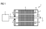
- FIG. 1 shows in a basic longitudinal section a rotary dynamoelectric machine 1, which drives a working machine 2 via a shaft 3.
- the rotary dynamoelectric machine 1 has a stator 4 which has, in axially extending grooves, a winding system 16 which forms winding heads on the end faces of the laminated core of the stator 4.
- the shaft 3 is non-rotatably connected to a rotor 5, which has permanent magnets and / or can also be designed as a cage rotor of an asynchronous machine.
- the rotor 5 interacts electromagnetically via an air gap 6 with the winding system 16 of the stator 4 and thus generates a torque which is transmitted via the shaft 3 to the working machine 2.
- the shaft 3 is held at least by means of a fixed bearing 12 in a housing 7 and rotates about an axis 17th
- FIG. 2 shows a perspective view of a sleeve 8, which prevents axial displacement of the shaft 3 against the fixed bearing 12.
- the sleeve 8 has on its inside an internal thread, which is preferably designed as a fine thread so as to obtain an exact axial positioning of the sleeve 8 on the shaft 3.
- holes 9 are provided, which facilitate the bias of the sleeve 8 on the shaft 3 by means of a tool, in particular a suitable hook key.
- the holes 9 are used to fix the sleeve 8 on the shaft 3 by 9 grub screws can be used in these holes.
- the holes 9 are evenly distributed on the peripheral surface of the sleeve 8 and are preferably according to FIG. 3 in an axial third or axial half of the sleeve 8, which faces the rotor 5. This leads to a running surface 10 on the rotor 5 facing away from the portion of the sleeve 8, which cooperates with a shaft seal 14.
- FIG. 3 The sleeve 8 is located axially between the working machine 2 and the fixed bearing 12 of the rotary dynamoelectric machine 1.
- the sleeve is positioned directly against the inner bearing ring of the fixed bearing 12 and against it braced. Due to the corresponding thread of the sleeve 8 and shaft 3, a precise axial positioning of the sleeve 8 on the shaft 3 is possible. This is an axial displacement of the shaft 3, which is supported on the inner ring of the fixed bearing 12 is no longer possible.
- a fixation of the sleeve 8 on the shaft 3 is ensured by a predetermined torque by means of a hook wrench and / or by grub screws in the holes 9 and / or by a sealing adhesive between the threads of sleeve 8 and shaft 3.
- the adhesive additionally prevents self-detachment of the sleeve 8 e.g. due to vibrations or a frictional torque of the shaft seal 14 and seals the thread gap.
- the shaft sealing ring 14 is provided radially outside the sleeve 8, which cooperates sealingly with the running surface 10 or sealing surface of the sleeve 8.
- the axial positioning of the sleeve 8 can be set very accurately on the shaft 3, and it will also small differences in diameter of axial sections of the shaft 3 for the introduction of a thread usable.
- the present invention is not reduced to rotary dynamoelectric machines, but rather can be applied to all rotating machinery or equipment.
Landscapes
- Engineering & Computer Science (AREA)
- General Engineering & Computer Science (AREA)
- Mechanical Engineering (AREA)
- Power Engineering (AREA)
- Motor Or Generator Frames (AREA)
Priority Applications (1)
| Application Number | Priority Date | Filing Date | Title |
|---|---|---|---|
| EP14151574.2A EP2897258A1 (fr) | 2014-01-17 | 2014-01-17 | Machine dynamoélectrique |
Applications Claiming Priority (1)
| Application Number | Priority Date | Filing Date | Title |
|---|---|---|---|
| EP14151574.2A EP2897258A1 (fr) | 2014-01-17 | 2014-01-17 | Machine dynamoélectrique |
Publications (1)
| Publication Number | Publication Date |
|---|---|
| EP2897258A1 true EP2897258A1 (fr) | 2015-07-22 |
Family
ID=49943268
Family Applications (1)
| Application Number | Title | Priority Date | Filing Date |
|---|---|---|---|
| EP14151574.2A Withdrawn EP2897258A1 (fr) | 2014-01-17 | 2014-01-17 | Machine dynamoélectrique |
Country Status (1)
| Country | Link |
|---|---|
| EP (1) | EP2897258A1 (fr) |
Cited By (2)
| Publication number | Priority date | Publication date | Assignee | Title |
|---|---|---|---|---|
| DE102019207324A1 (de) * | 2019-05-20 | 2020-11-26 | Zf Friedrichshafen Ag | Kühlanordnung für ein wärmeerzeugendes rotierendes Bauteil einer elektrischen Maschine sowie elektrische Maschine |
| US20240405622A1 (en) * | 2023-05-31 | 2024-12-05 | Valeo Eautomotive Germany Gmbh | Rotor for an electric machine with improved mountability of a rotor laminated core and production method therefor |
Citations (4)
| Publication number | Priority date | Publication date | Assignee | Title |
|---|---|---|---|---|
| GB946624A (en) * | 1961-11-09 | 1964-01-15 | Ass Elect Ind | Improvements relating to means for securing a part on a shaft |
| DE3611251A1 (de) * | 1986-04-04 | 1987-10-08 | Wittenstein Manfred | Auf das gewinde einer drehbar gelagerten welle aufschraubbare spannmutter |
| DE102007034914A1 (de) * | 2007-07-24 | 2009-02-05 | Sew-Eurodrive Gmbh & Co. Kg | Umrichtermotor und Verfahren zur Kühlung eines Umrichtermotors |
| DE102011082016A1 (de) * | 2011-09-01 | 2013-03-07 | Schaeffler Technologies AG & Co. KG | Vorspannmutter |
-
2014
- 2014-01-17 EP EP14151574.2A patent/EP2897258A1/fr not_active Withdrawn
Patent Citations (4)
| Publication number | Priority date | Publication date | Assignee | Title |
|---|---|---|---|---|
| GB946624A (en) * | 1961-11-09 | 1964-01-15 | Ass Elect Ind | Improvements relating to means for securing a part on a shaft |
| DE3611251A1 (de) * | 1986-04-04 | 1987-10-08 | Wittenstein Manfred | Auf das gewinde einer drehbar gelagerten welle aufschraubbare spannmutter |
| DE102007034914A1 (de) * | 2007-07-24 | 2009-02-05 | Sew-Eurodrive Gmbh & Co. Kg | Umrichtermotor und Verfahren zur Kühlung eines Umrichtermotors |
| DE102011082016A1 (de) * | 2011-09-01 | 2013-03-07 | Schaeffler Technologies AG & Co. KG | Vorspannmutter |
Cited By (2)
| Publication number | Priority date | Publication date | Assignee | Title |
|---|---|---|---|---|
| DE102019207324A1 (de) * | 2019-05-20 | 2020-11-26 | Zf Friedrichshafen Ag | Kühlanordnung für ein wärmeerzeugendes rotierendes Bauteil einer elektrischen Maschine sowie elektrische Maschine |
| US20240405622A1 (en) * | 2023-05-31 | 2024-12-05 | Valeo Eautomotive Germany Gmbh | Rotor for an electric machine with improved mountability of a rotor laminated core and production method therefor |
Similar Documents
| Publication | Publication Date | Title |
|---|---|---|
| DE112017000001B4 (de) | Rotor einer elektrischen Rotationsmaschine, elektrische Rotationsmaschine und Rotorelement einer elektrischen Rotationsmaschine | |
| DE102007014714B4 (de) | Spindelmotor | |
| EP2569848B1 (fr) | Procédé de fabrication d'un moteur électrique | |
| DE102004060351A1 (de) | Elektromotor für Rotation und Axialbewegung | |
| EP3189235B1 (fr) | Pompe à cavité progressive | |
| DE102013208980B4 (de) | Retarderwelle | |
| EP3659240B1 (fr) | Rotor d'une machine electrique | |
| WO2022012841A1 (fr) | Rotor pour machine électrique tournante, machine électrique | |
| EP1722459A1 (fr) | Machine électrique avec dispositif pour soutenir le rotor sur le partie frontal du stator | |
| WO2016037781A1 (fr) | Système de palier pour machines électriques | |
| EP2710712B1 (fr) | Rondelle de butée pour une machine électrique | |
| EP2369191A2 (fr) | Agencement de stockage doté de deux roulements à rotule | |
| DE102006051018B3 (de) | Spindelmotor mit radialen und axialen Lagersystemen | |
| EP2710711B1 (fr) | Rondelle de butée pour une machine électrique | |
| DE212018000250U1 (de) | Rotor für eine Elektromaschine | |
| DE69103756T2 (de) | Magnetische lager. | |
| EP3035503A1 (fr) | Machine dynamoélectrique dotée d'un frein | |
| AT520949A1 (de) | Fixierelement zur Fixierung der Rotorwelle einer elektrischen Maschine an deren Stator, sowie elektrische Maschine mit einem solchen Fixierelement | |
| DE202004003695U1 (de) | Hydrodynamisches Lagersystem zur Drehlagerung eines Spindelmotors | |
| DE102021104468B4 (de) | Verfahren zur Montage einer Axialflussmaschine in ein Gehäuse sowie Axialflussmaschine und Roboter | |
| DE102011118398A1 (de) | Rotor für eine elektrische Maschine | |
| EP3031963B1 (fr) | Broche de dispositif fausse torsion et dispositif fausse torsion | |
| EP1610020A2 (fr) | Actionneur d'embrayage double | |
| DE102015104369A1 (de) | Elektromotor mit Dichtungsbauteil und Verfahren zur Herstellung eines Elektromotors | |
| DE10256974B4 (de) | Elektrische Maschine |
Legal Events
| Date | Code | Title | Description |
|---|---|---|---|
| PUAI | Public reference made under article 153(3) epc to a published international application that has entered the european phase |
Free format text: ORIGINAL CODE: 0009012 |
|
| 17P | Request for examination filed |
Effective date: 20140117 |
|
| AK | Designated contracting states |
Kind code of ref document: A1 Designated state(s): AL AT BE BG CH CY CZ DE DK EE ES FI FR GB GR HR HU IE IS IT LI LT LU LV MC MK MT NL NO PL PT RO RS SE SI SK SM TR |
|
| AX | Request for extension of the european patent |
Extension state: BA ME |
|
| 17P | Request for examination filed |
Effective date: 20151218 |
|
| RBV | Designated contracting states (corrected) |
Designated state(s): AL AT BE BG CH CY CZ DE DK EE ES FI FR GB GR HR HU IE IS IT LI LT LU LV MC MK MT NL NO PL PT RO RS SE SI SK SM TR |
|
| RAP1 | Party data changed (applicant data changed or rights of an application transferred) |
Owner name: SIEMENS AKTIENGESELLSCHAFT |
|
| 17Q | First examination report despatched |
Effective date: 20171012 |
|
| STAA | Information on the status of an ep patent application or granted ep patent |
Free format text: STATUS: THE APPLICATION IS DEEMED TO BE WITHDRAWN |
|
| 18D | Application deemed to be withdrawn |
Effective date: 20190801 |