EP2897264B1 - Kernherstellungsvorrichtung und Kernherstellungsverfahren - Google Patents
Kernherstellungsvorrichtung und Kernherstellungsverfahren Download PDFInfo
- Publication number
- EP2897264B1 EP2897264B1 EP15151448.6A EP15151448A EP2897264B1 EP 2897264 B1 EP2897264 B1 EP 2897264B1 EP 15151448 A EP15151448 A EP 15151448A EP 2897264 B1 EP2897264 B1 EP 2897264B1
- Authority
- EP
- European Patent Office
- Prior art keywords
- jig
- core
- rotor core
- magnetic
- magnetization
- Prior art date
- Legal status (The legal status is an assumption and is not a legal conclusion. Google has not performed a legal analysis and makes no representation as to the accuracy of the status listed.)
- Not-in-force
Links
- 238000004519 manufacturing process Methods 0.000 title claims description 81
- 230000005415 magnetization Effects 0.000 claims description 113
- 239000002994 raw material Substances 0.000 claims description 45
- 230000004888 barrier function Effects 0.000 claims description 38
- 239000011800 void material Substances 0.000 claims description 30
- 238000001816 cooling Methods 0.000 claims description 16
- 230000002093 peripheral effect Effects 0.000 claims description 7
- 230000035699 permeability Effects 0.000 claims description 7
- 230000000903 blocking effect Effects 0.000 claims description 3
- 238000000034 method Methods 0.000 description 28
- 230000004907 flux Effects 0.000 description 27
- 230000008569 process Effects 0.000 description 27
- 238000003780 insertion Methods 0.000 description 22
- 230000037431 insertion Effects 0.000 description 22
- 230000000694 effects Effects 0.000 description 14
- 229910001172 neodymium magnet Inorganic materials 0.000 description 8
- 230000005347 demagnetization Effects 0.000 description 7
- 238000001746 injection moulding Methods 0.000 description 6
- 230000002427 irreversible effect Effects 0.000 description 6
- 238000002347 injection Methods 0.000 description 5
- 239000007924 injection Substances 0.000 description 5
- 229910000831 Steel Inorganic materials 0.000 description 4
- 230000003247 decreasing effect Effects 0.000 description 4
- 239000010959 steel Substances 0.000 description 4
- 230000015572 biosynthetic process Effects 0.000 description 3
- 230000005284 excitation Effects 0.000 description 3
- 238000010438 heat treatment Methods 0.000 description 3
- 239000008188 pellet Substances 0.000 description 3
- XEEYBQQBJWHFJM-UHFFFAOYSA-N Iron Chemical compound [Fe] XEEYBQQBJWHFJM-UHFFFAOYSA-N 0.000 description 2
- 239000006247 magnetic powder Substances 0.000 description 2
- 239000000463 material Substances 0.000 description 2
- 229910052779 Neodymium Inorganic materials 0.000 description 1
- 229910052742 iron Inorganic materials 0.000 description 1
- 239000000155 melt Substances 0.000 description 1
- 239000000203 mixture Substances 0.000 description 1
- 238000000465 moulding Methods 0.000 description 1
- QEFYFXOXNSNQGX-UHFFFAOYSA-N neodymium atom Chemical compound [Nd] QEFYFXOXNSNQGX-UHFFFAOYSA-N 0.000 description 1
- 239000000088 plastic resin Substances 0.000 description 1
- 229920006395 saturated elastomer Polymers 0.000 description 1
- 230000001360 synchronised effect Effects 0.000 description 1
- 230000007704 transition Effects 0.000 description 1
Images






Classifications
-
- H—ELECTRICITY
- H01—ELECTRIC ELEMENTS
- H01F—MAGNETS; INDUCTANCES; TRANSFORMERS; SELECTION OF MATERIALS FOR THEIR MAGNETIC PROPERTIES
- H01F13/00—Apparatus or processes for magnetising or demagnetising
- H01F13/003—Methods and devices for magnetising permanent magnets
-
- H—ELECTRICITY
- H02—GENERATION; CONVERSION OR DISTRIBUTION OF ELECTRIC POWER
- H02K—DYNAMO-ELECTRIC MACHINES
- H02K15/00—Processes or apparatus specially adapted for manufacturing, assembling, maintaining or repairing of dynamo-electric machines
- H02K15/02—Processes or apparatus specially adapted for manufacturing, assembling, maintaining or repairing of dynamo-electric machines of stator or rotor bodies
- H02K15/03—Processes or apparatus specially adapted for manufacturing, assembling, maintaining or repairing of dynamo-electric machines of stator or rotor bodies having permanent magnets
-
- Y—GENERAL TAGGING OF NEW TECHNOLOGICAL DEVELOPMENTS; GENERAL TAGGING OF CROSS-SECTIONAL TECHNOLOGIES SPANNING OVER SEVERAL SECTIONS OF THE IPC; TECHNICAL SUBJECTS COVERED BY FORMER USPC CROSS-REFERENCE ART COLLECTIONS [XRACs] AND DIGESTS
- Y10—TECHNICAL SUBJECTS COVERED BY FORMER USPC
- Y10T—TECHNICAL SUBJECTS COVERED BY FORMER US CLASSIFICATION
- Y10T29/00—Metal working
- Y10T29/49—Method of mechanical manufacture
- Y10T29/49002—Electrical device making
- Y10T29/49009—Dynamoelectric machine
- Y10T29/49012—Rotor
-
- Y—GENERAL TAGGING OF NEW TECHNOLOGICAL DEVELOPMENTS; GENERAL TAGGING OF CROSS-SECTIONAL TECHNOLOGIES SPANNING OVER SEVERAL SECTIONS OF THE IPC; TECHNICAL SUBJECTS COVERED BY FORMER USPC CROSS-REFERENCE ART COLLECTIONS [XRACs] AND DIGESTS
- Y10—TECHNICAL SUBJECTS COVERED BY FORMER USPC
- Y10T—TECHNICAL SUBJECTS COVERED BY FORMER US CLASSIFICATION
- Y10T29/00—Metal working
- Y10T29/53—Means to assemble or disassemble
- Y10T29/5313—Means to assemble electrical device
- Y10T29/53143—Motor or generator
Definitions
- the present invention relates to a core manufacturing device and a core manufacturing method.
- IPM Interior Permanent Magnet
- Japanese Patent No. 4726105 describes an example of a manufacturing method for a rotor core for use in the IPM motors.
- a cylindrical rotor core in which a plurality of magnet insertion holes are formed is shaped, and thereafter magnet raw materials before being magnetized are injected into the magnet insertion holes through injection molding.
- a magnetization device is disposed so as to cover the outer periphery of the rotor core, and magnetic flux is supplied from the magnetization device to the rotor core to magnetize the magnet raw materials disposed in the magnet insertion holes. Consequently, the magnet raw materials are magnetized to be turned into permanent magnets, thus completing the manufacture of a rotor core with embedded permanent magnets.
- Permanent magnets e.g. neodymium magnets (Nd-Fe-B magnets) used for field excitation for motors have such properties that the permanent magnets can be magnetized by even a weak external magnetic field as the temperature of the permanent magnets becomes higher. Therefore, it is advantageous to heat the rotor core to a high temperature in the magnetization process.
- Nd-Fe-B magnets neodymium magnets
- the permanent magnets of the rotor core may be irreversibly demagnetized depending on the timing to detach the rotor core from the magnetization device.
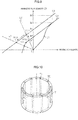
- the magnetization properties of the permanent magnets such as neodymium magnets are varied in accordance with the temperature as illustrated in FIG. 20 , for example.
- C1, C2, and C3 indicate an initial magnetization curve, a B-H curve at a normal temperature, and a B-H curve at a high temperature, respectively, for the permanent magnets such as neodymium magnets.
- the permanent magnets such as neodymium magnets have such properties that as the temperature rises, the absolute value of the coercive force becomes smaller, and the absolute value of the magnetic field corresponding to the inflection point becomes smaller.
- the magnetic flux density of the magnet raw materials of the rotor core is increased from zero along the initial magnetization curve C1 by a magnetic field generated by the magnetization device.
- the magnet raw materials are magnetized to be turned into permanent magnets.
- the magnetization of the permanent magnets is substantially saturated so that the permanent magnets are completely magnetized, the magnetic flux density of the permanent magnets reaches a magnetic flux density Bs1.
- the B-H curve for the permanent magnets transitions from the high-temperature B-H curve C3 to the normal-temperature B-H curve C2 as indicated by the arrow a1 in the drawing.
- the magnetic flux density of the permanent magnets is increased from the magnetic flux density Bs1 corresponding to the high-temperature B-H curve C3 to a magnetic flux density Bs2 corresponding to the normal-temperature B-H curve C2.
- the magnetic flux density of the permanent magnets is varied to a magnetic flux density Bd1 on an operation point P1, which is an intersection point between the normal-temperature B-H curve C2 and a permeance line L1, as indicated by the arrow a2 in the drawing. Because the operation point P1 is positioned on a straight portion of the normal-temperature B-H curve C2, the permanent magnets are not irreversibly demagnetized.
- the rotor core that has been subjected to the magnetization process is detached from the magnetization device without being cooled in the magnetization device, in contrast, the rotor core is detached from the magnetization device with the rotor core still at a high temperature.
- the magnetic flux density of the permanent magnets is varied along the high-temperature B-H curve C3 as indicated by the arrow b in the drawing. That is, the magnetic flux density of the permanent magnets is varied to a magnetic flux density Bd2 on an operation point P2, which is an intersection point between the high-temperature B-H curve C3 and the permeance line L1. In this event, the operation point P2 is lower than an inflection point Pcn of the high-temperature B-H curve C3.
- the operation point of the permanent magnets is only varied from P2 to P3. That is, compared to a case where the rotor core is cooled in the magnetization device, the magnetic flux density of the permanent magnets is demagnetized by a difference ⁇ Bd between the magnetic flux density Bd1 corresponding to the operation point P1 and a magnetic flux density Bd3 corresponding to the operation point P3. If the permanent magnets are irreversibly demagnetized in this way, the amount of effective magnetic flux that interlinks with a stator coil may be decreased to reduce motor output torque.
- An object of the present invention is to provide a core manufacturing device and a core manufacturing method capable of securing productivity while suppressing irreversible demagnetization of permanent magnets provided in a core.
- An aspect of the present invention provides a manufacturing device for a core, including: a magnetization device that magnetizes magnet raw materials before being magnetized provided in the heated core to turn the magnet raw materials before being magnetized into permanent magnets; a detachment device that detaches the heated core from the magnetization device; and a mounting device that mounts a jig composed of a magnetic body or an electromagnet to the heated core.
- the jig is being mounted around the detached core when the heated core, which is to be cooled, is detached from the magnetization device by the detachment device.
- Another aspect of the present invention provides a manufacturing method for a core, including: magnetizing magnet raw materials before being magnetized provided in the core using a magnetization device to turn the magnet raw materials before being magnetized into permanent magnets; detaching the magnetized core from the magnetization device; mounting a jig composed of a magnetic body or an electromagnet to the core; and cooling the core with a relative permeability around the core detached from the magnetization device maintained at a value of more than one by the jig mounted to the core.
- the core can be cooled with the relative permeability around the core maintained at a value of more than one by the jig mounted to the core when the core is detached from the magnetization device. Consequently, compared to a case where the core is cooled in an atmosphere with the jig not mounted thereto, the magnetic resistance of the magnetic circuit formed by the permanent magnets in the core is reduced. Therefore, it is possible to increase the permeance coefficient of the permanent magnets. As illustrated in FIG.
- the permeance line for the permanent magnets during cooling corresponds to a line L2, the absolute value of the slope of which is larger than that of a line L1 corresponding to a case where the core is cooled with the jig not mounted thereto. Consequently, the permanent magnets can be cooled with the operation point of the permanent magnets positioned at a point P4, which is higher than the inflection point Pcn of the high-temperature B-H curve C3. Therefore, it is possible to suppress irreversible demagnetization of the permanent magnets.
- the core is cooled after the core is detached from the magnetization device. Therefore, the magnetization device can also be used while the core is being cooled. Consequently, compared to a case where the core is cooled with the core attached to the magnetization device, it is possible to shorten the cycle time of the magnetization device, thus securing productivity.
- the mounting device may be configured to mount the jig to the core detached from the magnetization device by the detachment device.
- the jig may be composed of a soft magnetic body; the mounting device may be configured to mount the jig to the core before the magnet raw materials are magnetized; and the detachment device may be configured to detach the core together with the jig from the magnetization device.
- the jig can be easily mounted to the core.
- the magnetization process is performed on the core to which the jig is mounted.
- magnetic paths that short-circuit different magnetic poles are formed via the jig in the magnetization device. Such magnetic paths may generate leakage flux when magnetic flux is supplied from the magnetization device to the magnet raw materials, which may reduce the rate of magnetization of the permanent magnets.
- the core may be formed in a cylindrical shape, and may have different magnetic poles provided in an outer peripheral portion by the permanent magnets and arranged alternately at equiangular intervals along a circumferential direction; the jig may have magnetic barriers arranged at the equiangular intervals in the circumferential direction; the mounting device may mount the jig to the core such that the magnetic barriers are disposed at positions corresponding to boundary lines between different magnetic poles of the core that are adjacent in the circumferential direction; and the detachment device may be configured to detach the core together with the jig from the magnetization device after removing the magnetic barriers from the positions corresponding to the boundary lines between the magnetic poles.
- the magnetic barriers are removed from the positions corresponding to the boundary lines between the magnetic poles of the core. Therefore, magnetic paths that short-circuit different magnetic poles that are adjacent in the circumferential direction are easily formed in the core described above. As a result, it is possible to adequately secure a relative permeability around the core of more than one.
- the detachment device may be configured to remove the magnetic barriers from the positions corresponding to the boundary lines between the magnetic poles by rotating the jig relative to the core to offset positions of the magnetic barriers from the positions corresponding to the boundary lines between the magnetic poles.
- the magnetic barriers can be easily removed from the positions corresponding to the boundary lines between the magnetic poles of the core.
- the detachment device may be configured to offset the positions of the magnetic barriers to centers of the magnetic poles when rotating the jig relative to the core to offset the positions of the magnetic barriers from the positions corresponding to the boundary lines between the magnetic poles.
- the jig may be composed of a cylindrical member having an inside diameter that is larger than an outside diameter of the core, and may have void portions extending in an axial direction and formed at the equiangular intervals; and the magnetic barriers may be composed of the void portions or a non-magnetic body inserted into the void portions.
- the jig may be composed of a first jig composed of a cylindrical member having an inside diameter that is larger than an outside diameter of the core, and having void portions that open in an end surface in an axial direction as the magnetic barriers, and a second jig composed of a soft magnetic body and inserted into the void portions from opening portions of the void portions formed in the end surface of the first jig in the axial direction; and the detachment device may be configured to remove the magnetic barriers from the positions corresponding to the boundary lines between the magnetic poles by blocking the void portions of the first jig with the second jig.
- the magnetic barriers can be easily removed from the positions corresponding to the boundary lines between the magnetic poles of the core.
- the rotor core according to the embodiment is a so-called inner rotor used in a synchronous motor and disposed inside a cylindrical stator.
- a rotor core 1 is formed in a cylindrical shape around an axis m1.
- the rotor core 1 is structured by stacking a plurality of electromagnetic steel sheets in the axial direction.
- a plurality of magnet insertion holes 10 are formed at equiangular intervals in the circumferential direction to penetrate the rotor core 1 in the axial direction.
- the magnet insertion holes 10 have a U shape that opens toward the outer peripheral side of the rotor core in cross section taken along a plane that is orthogonal to the axial direction of the rotor core.
- Permanent magnets 2 are disposed in the magnet insertion holes 10.
- the permanent magnets 2 are composed of bond magnets such as neodymium magnets (Nd-Fe-B magnets).
- Portions of the permanent magnets 2 inside and outside the U shape have different magnetic poles.
- permanent magnets 2 having N pole in the portion inside the U shape and permanent magnets 2 having S pole in the portion inside the U shape are disposed alternately in the circumferential direction. Consequently, the rotor core 1 has a 10-pole structure in which N poles and S poles are arranged alternately along the circumferential direction in the outer peripheral portion of the rotor core 1.
- a manufacturing device and a manufacturing method for the rotor core 1 will be described.
- the basic structure of the rotor core 1 is formed by stacking a plurality of electromagnetic steel sheets in the axial direction, the electromagnetic steel sheets having U-shaped magnet insertion holes 10 formed at equiangular intervals in the circumferential direction.
- the rotor core 1 is heated using a heater device (not illustrated), and thereafter the heated rotor core 1 is attached to a magnetization device 3 as illustrated in FIG. 2 .
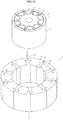
- the magnetization device 3 includes a plurality of permanent magnets 30 and a plurality of magnetization yokes 31 disposed alternately in the circumferential direction about an axis m2 and integrally assembled into an annular shape by an assembly member (not illustrated).
- the permanent magnets 30 are formed such that the width in the circumferential direction about the axis m2 becomes larger toward the radially outer side, and have different magnetic poles at both end portions in the circumferential direction.
- the permanent magnets 30 are disposed such that opposing magnetic poles of permanent magnets 30 that are adjacent in the circumferential direction about the axis m2 are of the same magnetic polarity.
- the magnetization yokes 31 are interposed between opposing portions of the permanent magnets 30 of the same magnetic polarity.
- the rotor core 1 heated in the heating process is inserted into an insertion hole 32 formed in the center portion of the magnetization device 3 by a conveyance device (not illustrated).
- a conveyance device not illustrated.
- portions on the inner side of the U shape of the magnet insertion holes 10 oppose the inner peripheral portions of the magnetization yokes 31, and portions at the boundaries between magnet insertion holes 10 that are adjacent in the circumferential direction of the rotor core oppose the inner peripheral portions of the permanent magnets 30. Attachment of the rotor core 1 to the magnetization device 3 is thus completed.
- a magnet raw material before being magnetized is injected from an injection machine 5 into the magnet insertion holes 10 of the rotor core 1 via the die 4.
- the magnet raw material is prepared by mixing magnetic powder such as neodymium magnetic powder before being magnetized with a plastic resin and molding and solidifying the mixture.
- the injection machine 5 has an input portion 50. Magnet raw material pellets 51 are input to the input portion 50.
- the magnet raw material pellets 51 are prepared by granulating the magnet raw material.
- the injection machine 5 heats and melts the magnet raw material pellets 51 input to the input portion 50, and injects the molten magnet raw material into an inlet port 40 of the die 4. Passages that extend from the inlet port 40 to the magnet insertion holes 10 of the rotor core 1 are formed in the die 4.
- the magnet raw material at a high temperature injected from the injection machine 5 into the inlet port 40 of the die 4 is injected into the magnet insertion holes 10 of the rotor core 1 through the passages inside the die 4 for injection molding.
- the magnet raw material that has flowed into the magnet insertion holes 10 of the rotor core 1 is maintained at a high temperature. Consequently, the flowability of the magnet raw material is secured, thus enabling the magnet raw material to be easily embedded in the magnet insertion holes 10.
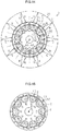
- the magnetization device 3 applies magnetic flux indicated by the arrows in the drawing to magnet raw materials 6 embedded in the magnet insertion holes 10 of the rotor core 1. That is, magnetic flux generated by the permanent magnets 30 passes in the order of the magnetization yoke 31 that is adjacent to the N pole of the permanent magnet 30, the rotor core 1, the magnet raw material 6, the rotor core 1, and the magnetization yoke 31 that is adjacent to the S pole of the permanent magnet 30. Consequently, magnetic paths extending from the outer side toward the inner side of the U shape or magnetic paths extending from the inner side toward the outer side of the U shape are formed in the magnet raw materials 6.
- the magnet raw materials 6 embedded in the rotor core 1 are magnetized such that the inside of the U shape serves as the N pole, or such that the inside of the U shape serves as the S pole.
- the process in which the magnet raw materials 6 are injected into the magnet insertion holes 10 of the rotor core 1 for injection molding and the process in which the magnet raw materials 6 embedded in the magnet insertion holes 10 are magnetized are executed substantially at the same time.
- the magnet raw materials 6 are composed of neodymium magnets or the like as in the embodiment, the magnet raw materials 6 have such properties that as the temperature becomes higher, the magnet raw materials 6 are more easily magnetized.
- the magnet raw materials 6 are injected into the rotor core 1 which has been heated in the heating process, and therefore the magnet raw materials 6 can be magnetized while being maintained at a high temperature. Therefore, the magnetic flux density of the permanent magnets 2 after being magnetized can be increased.
- the process in which the rotor core 1 is detached from the magnetization device 3 and the process in which a jig 7 is mounted to the rotor core 1 are performed at the same time.
- the jig 7 is composed of a cylindrical soft magnetic body.
- the inside diameter of the jig 7 is set to be slightly larger than the outside diameter of the rotor core 1.
- the length of the jig 7 in the axial direction is set to be equal to or more than the length of the rotor core 1 in the axial direction.
- the rotor core 1 is immediately detached from the magnetization device 3.
- the rotor core 1 is detached from the magnetization device 3 still at a high temperature (a temperature at which the inflection point falls within the second quadrant in the case where the properties of the magnetic circuit are represented by a B-H curve; in the embodiment, about 150°C).
- the jig 7 is first placed on the upper surface of the magnetization device 3 so as to be coaxial with the insertion hole 32 of the magnetization device 3.
- the detachment device 80 also functions as a mounting device that mounts the jig 7 to the outer periphery of the rotor core 1.
- the rotor core 1 is carried together with the jig 7 to a cooling line by a conveyance device (not illustrated).
- the cooling line as illustrated in FIG. 7 , the rotor core 1 is cooled with the jig 7 mounted to the outer periphery of the rotor core 1.
- the manufacture of the rotor core 1 is completed by detaching the jig 7 from the rotor core 1 after the rotor core 1 is completely cooled.
- the rotor core 1 By mounting the jig 7 composed of a magnetic body to the outer periphery of the rotor core 1 detached from the magnetization device 3 as illustrated in FIG. 7 , the rotor core 1 can be cooled with the relative permeability around the rotor core 1 maintained at a value of more than one. Consequently, as indicated by the arrows in FIG. 8 , magnetic paths that short-circuit different magnetic poles of permanent magnets 2 that are adjacent in the circumferential direction are easily formed via the jig 7 around the rotor core 1. Compared to a case where the rotor core 1 is cooled in an atmosphere with the jig 7 not mounted thereto, the magnetic resistance of the magnetic circuit formed by the permanent magnets 2 in the rotor core 1 is reduced.
- the permeance line for the permanent magnets 2 during cooling corresponds to a line L2, the absolute value of the slope of which is larger than that of a line L1 corresponding to a case where the rotor core 1 is cooled with the jig 7 not mounted thereto.
- the magnetic flux density and the operation point of the permanent magnets 2 according to the embodiment are varied as indicated by the arrows in the drawing.
- the magnetic field in the magnetizing direction applied from the magnetization device 3 to the permanent magnets 2 is decreased. Therefore, the magnetic flux density of the permanent magnets 2 is decreased from a magnetic flux density Bs1 indicated in FIG. 9 along a high-temperature B-H curve C3.
- the operation point of the permanent magnets 2 is positioned at an intersection point P10 between the high-temperature B-H curve C3 and the permeance line L2. That is, the operation point P10 of the permanent magnets 2 is higher than an inflection point Pcn of the high-temperature magnetization curve C3.
- the magnetization device 3 can also be used while the rotor core 1 is being cooled by cooling the rotor core 1 after the rotor core 1 is detached from the magnetization device 3. Compared to a case where the rotor core 1 is cooled with the rotor core 1 attached to the magnetization device 3, it is possible to shorten the cycle time of the magnetization device 3, thus improving productivity.
- the jig 7 can be easily mounted to the rotor core 1 by mounting the jig 7 to the rotor core 1 detached from the magnetization device 3.
- a plurality of void portions 70 are formed at equiangular intervals in the circumferential direction to penetrate the jig 7 according to the embodiment in the axial direction.
- Magnetic barrier members 71 composed of a non-magnetic body are embedded in the void portions 70.
- the rotor core 1 is heated. After that, as indicated by the long dashed double-short dashed lines in FIG. 11 , the jig 7 is mounted to the outer periphery of the rotor core 1 by a mounting device 81. At this time, the jig 7 is mounted to the rotor core 1 such that the magnetic barrier members 71 are disposed at positions corresponding to boundary lines n between different magnetic poles of the rotor core 1 that are adjacent in the circumferential direction. Next, as illustrated in FIG.
- the rotor core 1 is inserted together with the jig 7 into the insertion hole 32 of the magnetization device 3 by a conveyance device (not illustrated), and thereafter the injection molding process for the magnet raw materials illustrated in FIG. 3 and the magnetization process for the permanent magnets illustrated in FIG. 4 are performed.
- the rotor core 1 is detached together with the jig 7 from the magnetization device 3 by the detachment device 80.
- the detachment process first, the jig 7 is rotated relative to the rotor core 1 by the detachment device 80 to position the magnetic barrier members 71 at the center of the magnetic poles of the rotor core 1. After that, as illustrated in FIG.
- the bottom surfaces of the rotor core 1 and the jig 7 are pushed up by the detachment device 80 so that the rotor core 1 and the jig 7 are integrally detached from the magnetization device 3.
- the rotor core 1 and the jig 7 are carried to a cooling line by a conveyance device (not illustrated). In the cooling line, the rotor core 1 is cooled with the jig 7 mounted to the outer periphery of the rotor core 1.
- the manufacture of the rotor core 1 is completed by detaching the jig 7 from the rotor core 1 after the rotor core 1 is completely cooled.
- the jig 7 can be easily mounted to the rotor core 1 by mounting the jig 7 to the rotor core 1 before being subjected to the magnetization process.
- the manufacturing device and the manufacturing method according to the embodiment are the same as those according to the first embodiment in that the rotor core 1 is cooled after the rotor core 1 is detached from the magnetization device 3. Therefore, an advantageous effect that is similar to the effect (2) of the first embodiment can be obtained.
- a third embodiment of a manufacturing device and a manufacturing method for a rotor core will be described. Differences of the embodiment from the second embodiment will be mainly described.
- a plurality of void portions 70 are formed at equiangular intervals in the circumferential direction to penetrate the jig 7 according to the embodiment in the axial direction. It should be noted, however, that the embodiment is different from the second embodiment in that the magnetic barrier members 71 are not embedded in the void portions 70.
- the jig 7 will be referred to as a first jig for convenience.
- a second jig 9 that is separate from the first jig 7 is used.
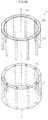
- the second jig 9 is composed of a soft magnetic body, and has an annular portion 90 and a plurality of cylindrical pins 91 formed at equiangular intervals on an end surface of the annular portion 90 in the axial direction.
- the outside diameter of the pins 91 is set to be generally equal to the inside diameter of the void portions 70 of the first jig 7.
- the length of the pins 91 in the axial direction is set to be generally equal to the length of the void portions 70 of the first jig 7 in the axial direction.
- All the void portions 70 of the first jig 7 can be blocked by the pins 91 by mounting the second jig 9 to the first jig 7 with the pins 91 inserted into the void portions 70 through opening portions formed in an end surface of the first jig 7 in the axial direction.
- the first jig 7 is mounted to the rotor core 1, and the rotor core 1 is mounted to the magnetization device 3.
- the first jig 7 is mounted to the rotor core 1 such that the void portions 70 are disposed at positions corresponding to the boundary lines n between different magnetic poles of the rotor core 1 that are adjacent in the circumferential direction.
- the rotor core 1 is inserted together with the first jig 7 into the insertion hole 32 of the magnetization device 3 by a conveyance device (not illustrated). After that, the injection molding process for the magnet raw materials illustrated in FIG.
- the rotor core 1 is pushed up together with the first jig 7 and the second jig 9 by the detachment device 80 so that the rotor core 1, the first jig 7, and the second jig 9 are integrally detached from the magnetization device 3.
- the rotor core 1 is carried together with the first jig 7 and the second jig 9 to a cooling line by a conveyance device (not illustrated).
- the rotor core 1 is cooled with the first jig 7 mounted to the outer periphery of the rotor core 1 and with the second jig 9 mounted to the first jig 7.
- the manufacture of the rotor core 1 is completed by detaching the first jig 7 and the second jig 9 from the rotor core 1 after the rotor core 1 is completely cooled.
- the jig 7 can be easily mounted to the rotor core 1 by mounting the first jig 7 to the rotor core 1 before being subjected to magnetization.
- the manufacturing device and the manufacturing method according to the embodiment are the same as those according to the first embodiment in that the rotor core 1 is cooled after the rotor core 1 is detached from the magnetization device 3. Therefore, an advantageous effect that is similar to the effect (2) of the first embodiment can be obtained.
- the jig 7 is composed of a soft magnetic body.
- the jig 7 may be composed of any material that forms magnetic paths that short-circuit different magnetic poles of the permanent magnets 2 that are adjacent in the circumferential direction in the rotor core 1, and may be composed of a permanent magnet, an electromagnet, or the like, for example.
- the jig 7 may be composed of a combination of a plurality of a soft magnetic body, a permanent magnet, and an electromagnet, for example.
- the jig 7 to be mounted to the rotor core 1 is formed in a cylindrical shape.
- the shape of the jig 7 may be changed as appropriate.
- a pair of disk members 72a, 72b that can cover both end surfaces of the rotor core 1 in the axial direction, for example, may be used as the jig 7.
- FIG. 19 if the disk members 72a, 72b are brought into abutment with both end surfaces of the rotor core 1, magnetic paths that short-circuit different magnetic poles of permanent magnets 2 that are adjacent in the circumferential direction are formed via the disk members 72a, 72b in the rotor core 1. Therefore, the same effect as that of the jig 7 according to the first embodiment can be obtained.
- a similar structure may be used in the second embodiment and the third embodiment.
- the magnetic barrier members 71 are embedded in the void portions 70 of the jig 7.
- the void portions 70 in which the magnetic barrier members 71 are not embedded may be used as magnetic barriers.
- the magnetic barrier members 71 are positioned at the center of the magnetic poles of the rotor core 1 when the rotor core 1 is cooled.
- the positions of the magnetic barrier members 71 may be changed to any position offset from the boundary lines n between different magnetic poles of the rotor core 1 that are adjacent in the circumferential direction.
- the void portions 70 formed in the jig 7 according to the second embodiment and the third embodiment are not limited to being shaped so as to penetrate the jig 7 in the axial direction 7, and may be shaped as appropriate such as being open only in one of both end surfaces of the jig 7 in the axial direction, for example.
- the shape of the void portions 70 of the first jig 7 is changed in the third embodiment, the shape of the second jig 9 is accordingly changed.
- the rotor core 1 is composed of electromagnetic steel sheets.
- a soft magnetic body such as electromagnetic soft iron, for example, may also be used as the material of the rotor core 1.
- bond magnets are used as the permanent magnets 2 used in the rotor core 1.
- sintered magnets, compression-molded magnets, or the like, for example, may also be used as the permanent magnets 2.
- the permanent magnets 2 embedded in the rotor core 1 have a generally U shape in cross section taken along a plane that is orthogonal to the axial direction of the rotor core.
- the shape of the permanent magnets 2 is not limited thereto.
- the permanent magnets 2 may have a linear shape, a V shape, or an angular C shape in cross section taken along a plane that is orthogonal to the axial direction of the rotor core, for example.
- the rotor core 1 according to the embodiments have a 10-pole structure.
- the number of magnetic poles of the rotor core 1 is not limited, and may be changed as appropriate.
- the rotor core 1 is structured with the permanent magnets 2 embedded.
- the structure of the rotor core 1 is not limited thereto.
- the rotor core 1 may be structured with permanent magnets bonded to the outer peripheral surface, for example.
- the structure of the detachment device 80 according to the embodiments may be changed as appropriate as long as the rotor core 1 can be detached from the magnetization device 3.
- the structure of the mounting device 81 may be changed as appropriate as long as the jig 7 can be attached to the rotor core 1.
- the embodiments are not limited to being applied to a manufacturing device and a manufacturing method for an inner rotor, and may also be applied to a manufacturing device and a manufacturing method for an outer rotor or an axial-gap rotor, for example.
- the embodiments are not limited to being applied to a manufacturing device and a manufacturing method for the rotor core 1, and may also be applied to a manufacturing device and a manufacturing method for a suitable core provided with permanent magnets such as a stator core used in a brushed DC motor and provided with magnets for field excitation, for example.
Landscapes
- Engineering & Computer Science (AREA)
- Power Engineering (AREA)
- Manufacturing & Machinery (AREA)
- Permanent Field Magnets Of Synchronous Machinery (AREA)
- Manufacture Of Motors, Generators (AREA)
Claims (9)
- Herstellungsvorrichtung für einen Kern (1), mit:einer Magnetisierungsvorrichtung (3), die Magnet-Rohmaterialien (6), welche in dem erwärmten Kern (1) vorgesehen und zuvor nicht magnetisiert sind, magnetisiert, um die zuvor unmagnetisierten Magnet-Rohmaterialien (6) in Permanentmagnete (2) umzuwandeln; gekennzeichnet durcheine Trennungsvorrichtung (80), welche den erwärmten Kern (1) aus der Herstellungsvorrichtung (3) trennt; undeine Montiervorrichtung (81), welche ein Montagegestell (7), das aus einem magnetischen Körper oder einem Elektromagneten aufgebaut ist, auf den erwärmten Kern (1) montiert, wobeidas Montagegestell (7) um den herausgelösten Kern (1) herum montiert ist, wenn der zu kühlende erwärmte Kern (1) durch die Trennungsvorrichtung (80) aus der Magnetisierungsvorrichtung (3) getrennt ist.
- Herstellungsvorrichtung gemäß Anspruch 1, wobeidie Montiervorrichtung (81) dazu ausgelegt ist, das Montagegestell (7) an dem durch die Trennungsvorrichtung (80) von der Magnetisierungsvorrichtung (3) getrennten, erwärmten Kern (1) zu montieren.
- Herstellungsvorrichtung gemäß Anspruch 1, wobeidas Montagegestell (7) aus einem weichmagnetischen Körper aufgebaut ist;die Montiervorrichtung (81) dazu ausgelegt ist, das Montagegestell (7) an dem erwärmten Kern (1) zu montieren bevor die Magnet-Rohmaterialien (6) magnetisiert sind; unddie Trennungsvorrichtung (80) dazu ausgelegt ist, den erwärmten Kern (1) zusammen mit dem Montagegestell (7) aus der Magnetisierungsvorrichtung (3) zu trennen.
- Herstellungsvorrichtung gemäß Anspruch 3, wobeider erwärmte Kern (1) in einer zylindrischen Form ausgebildet ist und unterschiedliche magnetische Pole (S, N) aufweist, die in einem äußeren Umfangsabschnitt durch Permanentmagneten (2) bereitgestellt sind und entlang einer Umfangsrichtung alternierend in gleichwinkligen Abständen angeordnet sind;das Montagegestell (7) magnetische Barrieren (71) aufweist, die in Umfangsrichtung in gleichwinkligen Abständen angeordnet sind;die Montiervorrichtung (81) das Montagegestell (7) derart an den erwärmten Kern (1) montiert, dass die magnetischen Barrieren (71) an Positionen angeordnet sind, die Grenzlinien (n) zwischen in Umfangsrichtung zueinander benachbarten, unterschiedlichen magnetischen Polen (S, N) des Kerns (1) entsprechen; unddie Trennungsvorrichtung (80) dazu ausgelegt ist, den erwärmten Kern (1) zusammen mit dem Montagegestell (7) aus der Magnetisierungsvorrichtung (3) zu trennen, nachdem die magnetischen Barrieren (71) von den Positionen, die den Grenzlinien (n) zwischen den magnetischen Polen (S, N) entsprechen, entfernt sind.
- Herstellungsvorrichtung gemäß Anspruch 4, wobeidie Trennungsvorrichtung (80) dazu ausgelegt ist, die magnetischen Barrieren (71) von den Positionen, die den Grenzlinien (n) zwischen den magnetischen Polen (S, N) entsprechen, durch Rotieren des Montagegestells (7) relativ zu dem erwärmten Kern (1) zu entfernen, um die Positionen der magnetischen Barrieren (71) zu den Positionen entsprechend den Grenzlinien (n) zwischen den magnetischen Polen (S, N) zu versetzen.
- Herstellungsvorrichtung gemäß Anspruch 5, wobeidie Trennungsvorrichtung (80) dazu ausgelegt ist, die Positionen der magnetischen Barrieren (71) auf Mittelpunkte der magnetischen Pole (S, N) zu versetzen, wenn das Montagegestell (7) relativ zu dem erwärmten Kern (1) rotiert, um die Positionen der magnetischen Barrieren (71) zu den Positionen entsprechend den Grenzlinien (n) zwischen den magnetischen Polen (S, N) zu versetzen.
- Herstellungsvorrichtung gemäß einem der Ansprüche 4 bis 6, wobeidas Montagegestell (7) aus einem zylindrischen Bauteil mit einem Innendurchmesser aufgebaut ist, der größer ist als ein Außendurchmesser des erwärmten Kerns (1) und leere Abschnitte (70) aufweist, die sich in einer Axialrichtung erstrecken und in gleichwinkligen Abständen ausgebildet sind; unddie magnetischen Barrieren (71) aus den leeren Abschnitten (70) oder einem nicht-magnetischen Körper, der in die leeren Abschnitte (70) eingesetzt ist, aufgebaut sind.
- Herstellungsvorrichtung gemäß Anspruch 4, wobeidas Montagegestell (7) auseinem ersten Montagegestell (7), welches aus einem zylindrischen Bauteil mit einem Innendurchmesser aufgebaut ist, der größer ist als ein Außendurchmesser des erwärmten Kerns (1), und leere Abschnitte (70) aufweist, die in einer Endoberfläche in einer Axialrichtung offen sind, als die magnetischen Barrieren (71), undeinem zweiten Montagegestell (9) aufgebaut ist, welches aus einem weichmagnetischen Körper aufgebaut ist und in Axialrichtung von Öffnungsabschnitten der leeren Abschnitt (70) aus, die in der Endoberfläche des ersten Montagegestells (7) ausgebildet sind, in die leeren Abschnitte (70) eingesetzt sind; unddie Trennungsvorrichtung (80) dazu ausgelegt ist, die magnetischen Barrieren (71) von den Positionen, die den Grenzlinien (n) zwischen den magnetischen Polen (S, N) entsprechen, zu entfernen, indem die leeren Abschnitte (70) des ersten Montagegestells (7) mit dem zweiten Montagegestell (9) blockiert werden.
- Herstellungsverfahren für einen Kern (1), mit:Magnetisieren der zuvor nicht magnetisierten Magnet-Rohmaterialien (6), welche in dem erwärmten Kern (1) bereitgestellt sind, durch Verwendung einer Magnetisierungsvorrichtung (3), um die zuvor nicht magnetisierten Magnet-Rohmaterialien (6) in Permanentmagnete (2) umzuwandeln;Trennen des magnetisierten erwärmten Kerns (1) von der Magnetisierungsvorrichtung;Montieren eines Montagegestells (7), welches aus einem magnetischen Körper oder einem Elektromagneten aufgebaut ist, an dem erwärmten Kern (1); undKühlen des erwärmten Kerns (1) durch das an dem erwärmten Kern (1) montierten Montagegestell (7), wobei eine relative Permeabilität um den erwärmten aus der Magnetisierungsvorrichtung (3) getrennten Kern (1) herum bei einem Wert von mehr als eins gehalten wird.
Applications Claiming Priority (1)
| Application Number | Priority Date | Filing Date | Title |
|---|---|---|---|
| JP2014008533A JP6314494B2 (ja) | 2014-01-21 | 2014-01-21 | コアの製造装置及びコアの製造方法 |
Publications (3)
| Publication Number | Publication Date |
|---|---|
| EP2897264A2 EP2897264A2 (de) | 2015-07-22 |
| EP2897264A3 EP2897264A3 (de) | 2016-05-25 |
| EP2897264B1 true EP2897264B1 (de) | 2018-02-28 |
Family
ID=52347219
Family Applications (1)
| Application Number | Title | Priority Date | Filing Date |
|---|---|---|---|
| EP15151448.6A Not-in-force EP2897264B1 (de) | 2014-01-21 | 2015-01-16 | Kernherstellungsvorrichtung und Kernherstellungsverfahren |
Country Status (4)
| Country | Link |
|---|---|
| US (1) | US9812239B2 (de) |
| EP (1) | EP2897264B1 (de) |
| JP (1) | JP6314494B2 (de) |
| CN (1) | CN104795943B (de) |
Families Citing this family (17)
| Publication number | Priority date | Publication date | Assignee | Title |
|---|---|---|---|---|
| US9601976B2 (en) * | 2013-05-17 | 2017-03-21 | GM Global Technology Operations LLC | Method for injection molding rotor magnets |
| JP6600994B2 (ja) * | 2015-06-02 | 2019-11-06 | 株式会社ジェイテクト | 埋込磁石型ロータユニットの製造方法、および着磁装置 |
| JP6658140B2 (ja) * | 2016-03-14 | 2020-03-04 | トヨタ自動車株式会社 | ロータの製造方法 |
| JP6728864B2 (ja) * | 2016-03-25 | 2020-07-22 | 株式会社ジェイテクト | 配向着磁装置 |
| CN105680594A (zh) * | 2016-04-20 | 2016-06-15 | 京磁材料科技股份有限公司 | 永磁电机及其加工方法 |
| JP7042666B2 (ja) * | 2018-03-28 | 2022-03-28 | 株式会社三井ハイテック | 鉄心製品の製造方法 |
| DE102018118325A1 (de) * | 2018-07-30 | 2020-01-30 | Thomas Magnete Gmbh | Elektromotor |
| DE102018118328A1 (de) * | 2018-07-30 | 2020-01-30 | Thomas Magnete Gmbh | Elektromotor |
| DE102018118324A1 (de) * | 2018-07-30 | 2020-01-30 | Thomas Magnete Gmbh | Elektromotor |
| DE102018118326A1 (de) * | 2018-07-30 | 2020-01-30 | Thomas Magnete Gmbh | Elektromotor |
| DE102018118327A1 (de) * | 2018-07-30 | 2020-01-30 | Thomas Magnete Gmbh | Verfahren zur Herstellung eines Elektromotors |
| JP2020137182A (ja) * | 2019-02-14 | 2020-08-31 | アイシン・エィ・ダブリュ株式会社 | 回転電機用ロータの製造方法 |
| CN113875137B (zh) * | 2019-05-31 | 2024-05-31 | 爱知制钢株式会社 | 励磁元件的制造方法 |
| CN113875136A (zh) * | 2019-06-04 | 2021-12-31 | 三菱电机株式会社 | 磁化用环、磁化方法、磁化装置、转子、电动机、压缩机及空调装置 |
| JP7344098B2 (ja) * | 2019-11-22 | 2023-09-13 | 大同特殊鋼株式会社 | 永久磁石回転子の製造方法および製造装置 |
| CN111716104A (zh) * | 2020-07-10 | 2020-09-29 | 精进百思特电动(上海)有限公司 | 一种铁芯上装配磁钢的生产线 |
| CN115253902A (zh) * | 2022-06-15 | 2022-11-01 | 江苏奥莱佳能源有限公司 | 磁控环模秸秆成型制粒装置及制粒方法 |
Family Cites Families (7)
| Publication number | Priority date | Publication date | Assignee | Title |
|---|---|---|---|---|
| JPH07183124A (ja) * | 1993-12-24 | 1995-07-21 | Toshiba Corp | 永久磁石の着磁装置及び着磁方法 |
| JPH09285049A (ja) * | 1996-04-16 | 1997-10-31 | Toshiba Corp | 永久磁石ロータの組立方法 |
| JP4726105B2 (ja) | 2001-08-03 | 2011-07-20 | ヤマハ発動機株式会社 | 配向装置 |
| JP3741653B2 (ja) * | 2002-02-20 | 2006-02-01 | 三菱電機株式会社 | 永久磁石形電動機の製造方法及び圧縮機及び冷凍サイクル装置及び永久磁石形電動機の製造装置及び永久磁石の熱減磁抑制具 |
| JP2009171764A (ja) | 2008-01-17 | 2009-07-30 | Toyota Motor Corp | モータ用ロータの生産方法及び着磁装置 |
| US9666341B2 (en) * | 2010-04-05 | 2017-05-30 | Aichi Steel Corporation | Production method for anisotropic bonded magnet and production apparatus for same |
| JP2013247783A (ja) | 2012-05-25 | 2013-12-09 | Jtekt Corp | ロータ及びこれを備えた回転電機 |
-
2014
- 2014-01-21 JP JP2014008533A patent/JP6314494B2/ja not_active Expired - Fee Related
-
2015
- 2015-01-14 US US14/596,752 patent/US9812239B2/en not_active Expired - Fee Related
- 2015-01-16 CN CN201510023193.7A patent/CN104795943B/zh not_active Expired - Fee Related
- 2015-01-16 EP EP15151448.6A patent/EP2897264B1/de not_active Not-in-force
Non-Patent Citations (1)
| Title |
|---|
| None * |
Also Published As
| Publication number | Publication date |
|---|---|
| JP2015139248A (ja) | 2015-07-30 |
| CN104795943B (zh) | 2018-11-06 |
| US9812239B2 (en) | 2017-11-07 |
| EP2897264A3 (de) | 2016-05-25 |
| EP2897264A2 (de) | 2015-07-22 |
| US20150206642A1 (en) | 2015-07-23 |
| JP6314494B2 (ja) | 2018-04-25 |
| CN104795943A (zh) | 2015-07-22 |
Similar Documents
| Publication | Publication Date | Title |
|---|---|---|
| US9812239B2 (en) | Core manufacturing device | |
| US10050481B2 (en) | Permanent magnet type motor and method for manufacturing permanent magnet type motor | |
| JP5900528B2 (ja) | 内包磁石型インナーロータの製造装置 | |
| RU2554119C1 (ru) | Ротор для вращающейся электрической машины, вращающаяся электрическая машина и способ изготовления ротора для вращающейся электрической машины | |
| US10879778B2 (en) | Rotor of rotating electric machine and manufacturing method of the same | |
| US10804776B2 (en) | Bonded-magnet injection molding device and bonded-magnet injection molding method | |
| US10116193B2 (en) | Interior permanent magnet rotor and method and apparatus for manufacturing the same | |
| JP2015510388A (ja) | 電気機械 | |
| US10566859B2 (en) | Rotor | |
| EP3732774B1 (de) | Verfahren zur herstellung einer elektrischen maschine | |
| CN110875675A (zh) | 电机转子及其制造方法、电机、电动助力转向系统 | |
| JP2003047212A (ja) | 配向装置及び着磁装置 | |
| CN103633760A (zh) | 永磁铁式电动机及永磁铁式电动机的制造方法 | |
| JP2016213980A (ja) | 永久磁石形電動機の回転子の製造方法 | |
| JP2014003795A (ja) | 回転子およびその製造方法ならびに永久磁石モータ | |
| JP4701641B2 (ja) | 複合ボンド磁石、複合ボンド磁石の製造方法、複合ボンド磁石を搭載したdcブラシレスモータの回転子。 | |
| CN107394917B (zh) | 定向磁化装置以及磁铁埋入型转子 | |
| JP2015082854A (ja) | ロータおよびその製造方法 | |
| JP2017507046A (ja) | 永久磁石を製造するための射出成形金型 | |
| US20240221987A1 (en) | Apparatus for manufacturing rotor | |
| JP2016220286A (ja) | 埋込磁石型ロータの製造装置および埋込磁石型ロータの製造方法 | |
| JP2000253609A (ja) | 電動機の回転子およびその製造方法 | |
| JP2013192293A (ja) | ロータの製造方法 | |
| JP2012178902A (ja) | 永久磁石式回転機 | |
| JP2003284267A (ja) | 多極磁石体およびその製造方法 |
Legal Events
| Date | Code | Title | Description |
|---|---|---|---|
| PUAI | Public reference made under article 153(3) epc to a published international application that has entered the european phase |
Free format text: ORIGINAL CODE: 0009012 |
|
| 17P | Request for examination filed |
Effective date: 20150116 |
|
| AK | Designated contracting states |
Kind code of ref document: A2 Designated state(s): AL AT BE BG CH CY CZ DE DK EE ES FI FR GB GR HR HU IE IS IT LI LT LU LV MC MK MT NL NO PL PT RO RS SE SI SK SM TR |
|
| AX | Request for extension of the european patent |
Extension state: BA ME |
|
| PUAL | Search report despatched |
Free format text: ORIGINAL CODE: 0009013 |
|
| AK | Designated contracting states |
Kind code of ref document: A3 Designated state(s): AL AT BE BG CH CY CZ DE DK EE ES FI FR GB GR HR HU IE IS IT LI LT LU LV MC MK MT NL NO PL PT RO RS SE SI SK SM TR |
|
| AX | Request for extension of the european patent |
Extension state: BA ME |
|
| RIC1 | Information provided on ipc code assigned before grant |
Ipc: H02K 15/02 20060101AFI20160418BHEP Ipc: H02K 15/03 20060101ALI20160418BHEP |
|
| STAA | Information on the status of an ep patent application or granted ep patent |
Free format text: STATUS: REQUEST FOR EXAMINATION WAS MADE |
|
| 17P | Request for examination filed |
Effective date: 20161026 |
|
| RBV | Designated contracting states (corrected) |
Designated state(s): AL AT BE BG CH CY CZ DE DK EE ES FI FR GB GR HR HU IE IS IT LI LT LU LV MC MK MT NL NO PL PT RO RS SE SI SK SM TR |
|
| GRAP | Despatch of communication of intention to grant a patent |
Free format text: ORIGINAL CODE: EPIDOSNIGR1 |
|
| STAA | Information on the status of an ep patent application or granted ep patent |
Free format text: STATUS: GRANT OF PATENT IS INTENDED |
|
| INTG | Intention to grant announced |
Effective date: 20170901 |
|
| GRAS | Grant fee paid |
Free format text: ORIGINAL CODE: EPIDOSNIGR3 |
|
| GRAA | (expected) grant |
Free format text: ORIGINAL CODE: 0009210 |
|
| STAA | Information on the status of an ep patent application or granted ep patent |
Free format text: STATUS: THE PATENT HAS BEEN GRANTED |
|
| AK | Designated contracting states |
Kind code of ref document: B1 Designated state(s): AL AT BE BG CH CY CZ DE DK EE ES FI FR GB GR HR HU IE IS IT LI LT LU LV MC MK MT NL NO PL PT RO RS SE SI SK SM TR |
|
| REG | Reference to a national code |
Ref country code: GB Ref legal event code: FG4D Ref country code: CH Ref legal event code: EP |
|
| REG | Reference to a national code |
Ref country code: AT Ref legal event code: REF Ref document number: 975154 Country of ref document: AT Kind code of ref document: T Effective date: 20180315 |
|
| REG | Reference to a national code |
Ref country code: IE Ref legal event code: FG4D |
|
| REG | Reference to a national code |
Ref country code: DE Ref legal event code: R096 Ref document number: 602015008214 Country of ref document: DE |
|
| REG | Reference to a national code |
Ref country code: NL Ref legal event code: MP Effective date: 20180228 |
|
| REG | Reference to a national code |
Ref country code: LT Ref legal event code: MG4D |
|
| REG | Reference to a national code |
Ref country code: AT Ref legal event code: MK05 Ref document number: 975154 Country of ref document: AT Kind code of ref document: T Effective date: 20180228 |
|
| PG25 | Lapsed in a contracting state [announced via postgrant information from national office to epo] |
Ref country code: ES Free format text: LAPSE BECAUSE OF FAILURE TO SUBMIT A TRANSLATION OF THE DESCRIPTION OR TO PAY THE FEE WITHIN THE PRESCRIBED TIME-LIMIT Effective date: 20180228 Ref country code: NL Free format text: LAPSE BECAUSE OF FAILURE TO SUBMIT A TRANSLATION OF THE DESCRIPTION OR TO PAY THE FEE WITHIN THE PRESCRIBED TIME-LIMIT Effective date: 20180228 Ref country code: LT Free format text: LAPSE BECAUSE OF FAILURE TO SUBMIT A TRANSLATION OF THE DESCRIPTION OR TO PAY THE FEE WITHIN THE PRESCRIBED TIME-LIMIT Effective date: 20180228 Ref country code: NO Free format text: LAPSE BECAUSE OF FAILURE TO SUBMIT A TRANSLATION OF THE DESCRIPTION OR TO PAY THE FEE WITHIN THE PRESCRIBED TIME-LIMIT Effective date: 20180528 Ref country code: HR Free format text: LAPSE BECAUSE OF FAILURE TO SUBMIT A TRANSLATION OF THE DESCRIPTION OR TO PAY THE FEE WITHIN THE PRESCRIBED TIME-LIMIT Effective date: 20180228 Ref country code: FI Free format text: LAPSE BECAUSE OF FAILURE TO SUBMIT A TRANSLATION OF THE DESCRIPTION OR TO PAY THE FEE WITHIN THE PRESCRIBED TIME-LIMIT Effective date: 20180228 Ref country code: CY Free format text: LAPSE BECAUSE OF FAILURE TO SUBMIT A TRANSLATION OF THE DESCRIPTION OR TO PAY THE FEE WITHIN THE PRESCRIBED TIME-LIMIT Effective date: 20180228 |
|
| PG25 | Lapsed in a contracting state [announced via postgrant information from national office to epo] |
Ref country code: SE Free format text: LAPSE BECAUSE OF FAILURE TO SUBMIT A TRANSLATION OF THE DESCRIPTION OR TO PAY THE FEE WITHIN THE PRESCRIBED TIME-LIMIT Effective date: 20180228 Ref country code: LV Free format text: LAPSE BECAUSE OF FAILURE TO SUBMIT A TRANSLATION OF THE DESCRIPTION OR TO PAY THE FEE WITHIN THE PRESCRIBED TIME-LIMIT Effective date: 20180228 Ref country code: GR Free format text: LAPSE BECAUSE OF FAILURE TO SUBMIT A TRANSLATION OF THE DESCRIPTION OR TO PAY THE FEE WITHIN THE PRESCRIBED TIME-LIMIT Effective date: 20180529 Ref country code: BG Free format text: LAPSE BECAUSE OF FAILURE TO SUBMIT A TRANSLATION OF THE DESCRIPTION OR TO PAY THE FEE WITHIN THE PRESCRIBED TIME-LIMIT Effective date: 20180528 Ref country code: RS Free format text: LAPSE BECAUSE OF FAILURE TO SUBMIT A TRANSLATION OF THE DESCRIPTION OR TO PAY THE FEE WITHIN THE PRESCRIBED TIME-LIMIT Effective date: 20180228 Ref country code: AT Free format text: LAPSE BECAUSE OF FAILURE TO SUBMIT A TRANSLATION OF THE DESCRIPTION OR TO PAY THE FEE WITHIN THE PRESCRIBED TIME-LIMIT Effective date: 20180228 |
|
| PG25 | Lapsed in a contracting state [announced via postgrant information from national office to epo] |
Ref country code: AL Free format text: LAPSE BECAUSE OF FAILURE TO SUBMIT A TRANSLATION OF THE DESCRIPTION OR TO PAY THE FEE WITHIN THE PRESCRIBED TIME-LIMIT Effective date: 20180228 Ref country code: PL Free format text: LAPSE BECAUSE OF FAILURE TO SUBMIT A TRANSLATION OF THE DESCRIPTION OR TO PAY THE FEE WITHIN THE PRESCRIBED TIME-LIMIT Effective date: 20180228 Ref country code: EE Free format text: LAPSE BECAUSE OF FAILURE TO SUBMIT A TRANSLATION OF THE DESCRIPTION OR TO PAY THE FEE WITHIN THE PRESCRIBED TIME-LIMIT Effective date: 20180228 Ref country code: RO Free format text: LAPSE BECAUSE OF FAILURE TO SUBMIT A TRANSLATION OF THE DESCRIPTION OR TO PAY THE FEE WITHIN THE PRESCRIBED TIME-LIMIT Effective date: 20180228 |
|
| REG | Reference to a national code |
Ref country code: DE Ref legal event code: R097 Ref document number: 602015008214 Country of ref document: DE |
|
| PG25 | Lapsed in a contracting state [announced via postgrant information from national office to epo] |
Ref country code: SM Free format text: LAPSE BECAUSE OF FAILURE TO SUBMIT A TRANSLATION OF THE DESCRIPTION OR TO PAY THE FEE WITHIN THE PRESCRIBED TIME-LIMIT Effective date: 20180228 Ref country code: CZ Free format text: LAPSE BECAUSE OF FAILURE TO SUBMIT A TRANSLATION OF THE DESCRIPTION OR TO PAY THE FEE WITHIN THE PRESCRIBED TIME-LIMIT Effective date: 20180228 Ref country code: SK Free format text: LAPSE BECAUSE OF FAILURE TO SUBMIT A TRANSLATION OF THE DESCRIPTION OR TO PAY THE FEE WITHIN THE PRESCRIBED TIME-LIMIT Effective date: 20180228 Ref country code: DK Free format text: LAPSE BECAUSE OF FAILURE TO SUBMIT A TRANSLATION OF THE DESCRIPTION OR TO PAY THE FEE WITHIN THE PRESCRIBED TIME-LIMIT Effective date: 20180228 |
|
| PLBE | No opposition filed within time limit |
Free format text: ORIGINAL CODE: 0009261 |
|
| STAA | Information on the status of an ep patent application or granted ep patent |
Free format text: STATUS: NO OPPOSITION FILED WITHIN TIME LIMIT |
|
| 26N | No opposition filed |
Effective date: 20181129 |
|
| PG25 | Lapsed in a contracting state [announced via postgrant information from national office to epo] |
Ref country code: IT Free format text: LAPSE BECAUSE OF FAILURE TO SUBMIT A TRANSLATION OF THE DESCRIPTION OR TO PAY THE FEE WITHIN THE PRESCRIBED TIME-LIMIT Effective date: 20180228 Ref country code: SI Free format text: LAPSE BECAUSE OF FAILURE TO SUBMIT A TRANSLATION OF THE DESCRIPTION OR TO PAY THE FEE WITHIN THE PRESCRIBED TIME-LIMIT Effective date: 20180228 |
|
| PG25 | Lapsed in a contracting state [announced via postgrant information from national office to epo] |
Ref country code: MC Free format text: LAPSE BECAUSE OF FAILURE TO SUBMIT A TRANSLATION OF THE DESCRIPTION OR TO PAY THE FEE WITHIN THE PRESCRIBED TIME-LIMIT Effective date: 20180228 |
|
| REG | Reference to a national code |
Ref country code: CH Ref legal event code: PL |
|
| GBPC | Gb: european patent ceased through non-payment of renewal fee |
Effective date: 20190116 |
|
| PG25 | Lapsed in a contracting state [announced via postgrant information from national office to epo] |
Ref country code: LU Free format text: LAPSE BECAUSE OF NON-PAYMENT OF DUE FEES Effective date: 20190116 |
|
| REG | Reference to a national code |
Ref country code: BE Ref legal event code: MM Effective date: 20190131 |
|
| REG | Reference to a national code |
Ref country code: IE Ref legal event code: MM4A |
|
| PG25 | Lapsed in a contracting state [announced via postgrant information from national office to epo] |
Ref country code: BE Free format text: LAPSE BECAUSE OF NON-PAYMENT OF DUE FEES Effective date: 20190131 |
|
| PG25 | Lapsed in a contracting state [announced via postgrant information from national office to epo] |
Ref country code: GB Free format text: LAPSE BECAUSE OF NON-PAYMENT OF DUE FEES Effective date: 20190116 Ref country code: CH Free format text: LAPSE BECAUSE OF NON-PAYMENT OF DUE FEES Effective date: 20190131 Ref country code: LI Free format text: LAPSE BECAUSE OF NON-PAYMENT OF DUE FEES Effective date: 20190131 |
|
| PG25 | Lapsed in a contracting state [announced via postgrant information from national office to epo] |
Ref country code: IE Free format text: LAPSE BECAUSE OF NON-PAYMENT OF DUE FEES Effective date: 20190116 |
|
| PG25 | Lapsed in a contracting state [announced via postgrant information from national office to epo] |
Ref country code: TR Free format text: LAPSE BECAUSE OF FAILURE TO SUBMIT A TRANSLATION OF THE DESCRIPTION OR TO PAY THE FEE WITHIN THE PRESCRIBED TIME-LIMIT Effective date: 20180228 |
|
| PG25 | Lapsed in a contracting state [announced via postgrant information from national office to epo] |
Ref country code: PT Free format text: LAPSE BECAUSE OF FAILURE TO SUBMIT A TRANSLATION OF THE DESCRIPTION OR TO PAY THE FEE WITHIN THE PRESCRIBED TIME-LIMIT Effective date: 20180628 Ref country code: MT Free format text: LAPSE BECAUSE OF NON-PAYMENT OF DUE FEES Effective date: 20190116 |
|
| PGFP | Annual fee paid to national office [announced via postgrant information from national office to epo] |
Ref country code: FR Payment date: 20201210 Year of fee payment: 7 |
|
| PGFP | Annual fee paid to national office [announced via postgrant information from national office to epo] |
Ref country code: DE Payment date: 20210105 Year of fee payment: 7 |
|
| PG25 | Lapsed in a contracting state [announced via postgrant information from national office to epo] |
Ref country code: IS Free format text: LAPSE BECAUSE OF FAILURE TO SUBMIT A TRANSLATION OF THE DESCRIPTION OR TO PAY THE FEE WITHIN THE PRESCRIBED TIME-LIMIT Effective date: 20180628 |
|
| PG25 | Lapsed in a contracting state [announced via postgrant information from national office to epo] |
Ref country code: HU Free format text: LAPSE BECAUSE OF FAILURE TO SUBMIT A TRANSLATION OF THE DESCRIPTION OR TO PAY THE FEE WITHIN THE PRESCRIBED TIME-LIMIT; INVALID AB INITIO Effective date: 20150116 |
|
| PG25 | Lapsed in a contracting state [announced via postgrant information from national office to epo] |
Ref country code: MK Free format text: LAPSE BECAUSE OF FAILURE TO SUBMIT A TRANSLATION OF THE DESCRIPTION OR TO PAY THE FEE WITHIN THE PRESCRIBED TIME-LIMIT Effective date: 20180228 |
|
| REG | Reference to a national code |
Ref country code: DE Ref legal event code: R119 Ref document number: 602015008214 Country of ref document: DE |
|
| PG25 | Lapsed in a contracting state [announced via postgrant information from national office to epo] |
Ref country code: DE Free format text: LAPSE BECAUSE OF NON-PAYMENT OF DUE FEES Effective date: 20220802 |
|
| PG25 | Lapsed in a contracting state [announced via postgrant information from national office to epo] |
Ref country code: FR Free format text: LAPSE BECAUSE OF NON-PAYMENT OF DUE FEES Effective date: 20220131 |