EP2897362A1 - Appareil d'affichage d'image, procédé de commande associé et procédé pour afficher une image - Google Patents
Appareil d'affichage d'image, procédé de commande associé et procédé pour afficher une image Download PDFInfo
- Publication number
- EP2897362A1 EP2897362A1 EP14179003.0A EP14179003A EP2897362A1 EP 2897362 A1 EP2897362 A1 EP 2897362A1 EP 14179003 A EP14179003 A EP 14179003A EP 2897362 A1 EP2897362 A1 EP 2897362A1
- Authority
- EP
- European Patent Office
- Prior art keywords
- image
- output
- input
- output method
- processor
- Prior art date
- Legal status (The legal status is an assumption and is not a legal conclusion. Google has not performed a legal analysis and makes no representation as to the accuracy of the status listed.)
- Withdrawn
Links
Images


Classifications
-
- H—ELECTRICITY
- H04—ELECTRIC COMMUNICATION TECHNIQUE
- H04N—PICTORIAL COMMUNICATION, e.g. TELEVISION
- H04N13/00—Stereoscopic video systems; Multi-view video systems; Details thereof
- H04N13/30—Image reproducers
- H04N13/356—Image reproducers having separate monoscopic and stereoscopic modes
- H04N13/359—Switching between monoscopic and stereoscopic modes
-
- H—ELECTRICITY
- H04—ELECTRIC COMMUNICATION TECHNIQUE
- H04N—PICTORIAL COMMUNICATION, e.g. TELEVISION
- H04N13/00—Stereoscopic video systems; Multi-view video systems; Details thereof
- H04N13/10—Processing, recording or transmission of stereoscopic or multi-view image signals
- H04N13/106—Processing image signals
- H04N13/139—Format conversion, e.g. of frame-rate or size
-
- H—ELECTRICITY
- H04—ELECTRIC COMMUNICATION TECHNIQUE
- H04N—PICTORIAL COMMUNICATION, e.g. TELEVISION
- H04N13/00—Stereoscopic video systems; Multi-view video systems; Details thereof
- H04N13/10—Processing, recording or transmission of stereoscopic or multi-view image signals
- H04N13/106—Processing image signals
- H04N13/156—Mixing image signals
-
- H—ELECTRICITY
- H04—ELECTRIC COMMUNICATION TECHNIQUE
- H04N—PICTORIAL COMMUNICATION, e.g. TELEVISION
- H04N13/00—Stereoscopic video systems; Multi-view video systems; Details thereof
- H04N13/10—Processing, recording or transmission of stereoscopic or multi-view image signals
- H04N13/106—Processing image signals
- H04N13/172—Processing image signals image signals comprising non-image signal components, e.g. headers or format information
- H04N13/183—On-screen display [OSD] information, e.g. subtitles or menus
-
- H—ELECTRICITY
- H04—ELECTRIC COMMUNICATION TECHNIQUE
- H04N—PICTORIAL COMMUNICATION, e.g. TELEVISION
- H04N13/00—Stereoscopic video systems; Multi-view video systems; Details thereof
- H04N13/30—Image reproducers
- H04N13/361—Reproducing mixed stereoscopic images; Reproducing mixed monoscopic and stereoscopic images, e.g. a stereoscopic image overlay window on a monoscopic image background
-
- H—ELECTRICITY
- H04—ELECTRIC COMMUNICATION TECHNIQUE
- H04N—PICTORIAL COMMUNICATION, e.g. TELEVISION
- H04N21/00—Selective content distribution, e.g. interactive television or video on demand [VOD]
- H04N21/40—Client devices specifically adapted for the reception of or interaction with content, e.g. set-top-box [STB]; Operations thereof
- H04N21/47—End-user applications
- H04N21/485—End-user interface for client configuration
-
- H—ELECTRICITY
- H04—ELECTRIC COMMUNICATION TECHNIQUE
- H04N—PICTORIAL COMMUNICATION, e.g. TELEVISION
- H04N21/00—Selective content distribution, e.g. interactive television or video on demand [VOD]
- H04N21/80—Generation or processing of content or additional data by content creator independently of the distribution process; Content per se
- H04N21/81—Monomedia components thereof
- H04N21/816—Monomedia components thereof involving special video data, e.g 3D video
-
- H—ELECTRICITY
- H04—ELECTRIC COMMUNICATION TECHNIQUE
- H04N—PICTORIAL COMMUNICATION, e.g. TELEVISION
- H04N7/00—Television systems
- H04N7/01—Conversion of standards, e.g. involving analogue television standards or digital television standards processed at pixel level
Definitions
- Apparatuses and methods consistent with exemplary embodiments relate to an image display apparatus, a driving method thereof, and an image display method, and more particularly, to an image display apparatus which allows a screen to be naturally changed in response to displaying an image by changing a two-dimensional (2D) image to a three dimensional (3D) image or by changing a frame rate of the image, for example, in a digital television (DTV), a driving method thereof, and an image display method.
- 2D two-dimensional
- 3D three dimensional
- the DTVs Since integrated circuits (ICs) are attached to DTVs, and convert an input analog signal into a digital signal, the DTVs prevent deterioration in video and audio signals, and accurately restore the signals to remove dual screen and noise caused by reflection of an analog radio wave. Since the scan line of the DTVs is as many as 1050, the DTVs have a clear more detailed screen image as compared to analog TVs.
- functions to configure a multi screen in which screens of two or three broadcasting stations are simultaneously shown on one TV screen using functions for storing and processing a broadcast signal of the DTVs, to stop and expand a spontaneous operation, to reproduce the stored operation again, or to print the stored operation through a printer become versatile.
- the DTVs enable watching of a 3D stereoscopic image or watching of an image by changing an image frequency according to surrounding environments.
- the DTVs change an output method for an image. For example, in response to a change of 3D driving from an off state to an on state in the DTV, since one image output in a screen in the off state has to be output as a left-eye image and a right-eye image, a change in the image output method is necessary.
- the video graphic is broken or disrupted and output. That is, the video or graphic which is being output when the change process of the image output method being viewed occurs is brokenly viewed or disruptedly presented. For example, all scan lines of the image may not be presented and an image transient occurs.
- the transient is prevented from being viewed using the video, graphic or panel mute type function.
- the using mute method in the related art has a disadvantage whenever the output method is changed. Therefore, a black screen is viewed by a user for a mute period of time. As a result, the user has no choice but to watch the flickering of a screen in which the screen disappears and appears again.
- One or more exemplary embodiments may overcome the above disadvantages and other disadvantages not described above. However, it is understood that one or more exemplary embodiment are not required to overcome the disadvantages described above, and may not overcome any of the problems described above.
- One or more exemplary embodiments are to provide an image display apparatus which allows a screen to be naturally changed in response to displaying an image by changing a 2D image method to a 3D image method or by changing a frame rate of the image, for example, in a digital television (DTV), a driving method thereof, and an image display method.
- DTV digital television
- an apparatus for displaying an image may include: an image input unit configured to allow an image signal to be input; an image processor configured to process the input image signal; and a display unit configured to display the processed image signal.
- the image processor may acquire at least one image from the input image and output the acquired image in a generation duration period of an image of which an image output method is changed in response to the change of the image output method of the input image signal.
- the image processor may analyze the input image and determine the change of the image output method according to an analysis result.
- the image processor may change the image output method from two-dimension (2D) image method to a 3D image method in response to it being determined that the 3D image is being produced as an analysis result of an image format of the input image.
- the image processor may further include a user interface unit configured to receive a request for a change of the image output method from a user.
- the image processor may include a video/audio processor configured to process video and audio of the input image signal, and a graphic user interface (GUI) processor configured to acquire the at least one image from the video/audio processor and use the acquired at least one image as a GUI image in response to the change of the image output method.
- GUI graphic user interface
- the image processor may generate an image to which an animation effect is added using the acquired at least one image and output the image in a duration time period between a point of time at which the acquired at least one image is first output to the display unit and a point of time at which the image, of which the image output method is changed, is output.
- the image processor may further include a mixer configured to mix the acquired at least one image with an image output from the video/audio processor and output a mixing result to generate the image to which the animation effect is added while increasingly or continuously reducing a screen size or area occupied by the at least one image.
- a mixer configured to mix the acquired at least one image with an image output from the video/audio processor and output a mixing result to generate the image to which the animation effect is added while increasingly or continuously reducing a screen size or area occupied by the at least one image.
- the mixer may overlay the acquired at least one image, constituting a different layer, with the image output from the video/audio processor.
- the number of unit frames of the image to which the animation effect is added may be determined according to a frame rate of the display unit.
- the image processor may further include a frame rate converter (FRC) configured to change frame rates of the input image and the image of which the image output method is changed and output a conversion result.
- FRC frame rate converter
- a method of driving an image display apparatus may include: allowing an image signal to be input; processing the input image signal; and displaying the processed image signal.
- the processing of the input image signal may include acquiring at least one image from images of the input image signal, and outputting the acquired image in a generation duration time period of an image of which an image output method is changed, in response to change of the image output method of the input image signal.
- the outputting may include analyzing the input image and determining whether or not the image output method is changed according to an analysis result.
- the outputting may include changing the image output method from a 2D image method to a 3D image method in response to the 3D image being determined as an analysis result of an image format of the input image.
- the outputting may include receiving a request for the change of the image output method from a user.
- the outputting may include processing video and audio of the input image signal in a video/audio processor; and acquiring at least one image from images processed in a graphic user interface (GUI) processor and using the acquired image as a GUI image, in response to the change of the image output method.
- GUI graphic user interface
- the outputting may include generating an image to which an animation effect is added using the acquired at least one image, and outputting the image to a screen of a display unit in a duration time period between a point of time at which the acquired at least one image is first output to the screen of the display unit and a point of time at which the image, of which the image output method is changed, is output.
- the method may further include mixing the acquired at least one image with the image output from the video/audio processor and outputting a mixing result to generate the image to which the animation effect is added while increasingly reducing a size or area occupied by the at least one image.
- the mixing may include overlaying the acquired at least one image, constituting a different layer, with the image output from the video/audio processor.
- the number of unit frames of the image to which the animation effect is added may be determined according to a frame rate of the display unit.
- the outputting may include changing frame rates of the input image and the image of which the image output method is changed and outputting a conversion result.
- a method of displaying an image may include: outputting an input image signal to a screen; determining whether or not an image output method of the input image signal is changed; acquiring at least one image from the input image signal as a graphic user interface (GUI) image in response to the image output method being changed as a determination result; outputting the at least one image acquired as the GUI image; and outputting an image of which the image output method is changed in response to completion of change of the image output method.
- GUI graphic user interface
- the input image signal may be processed in and output from a video plane, and the at least one image acquired as the GUI image may be processed in and output from a graphic plane.
- the outputting of the at least one image may include mixing the at least one image processed in the graphic plane and the image of which the image output method is changed and processed in the video plane, and outputting a mixing result.
- a size or area of the first output GUI image occupied on the screen may be continuously or increasingly reduced until the change of the image output method is completed, in response to the change of the image output method.
- the outputting of the at least one image may include generating an image to which an animation effect is added using the at least one image acquired as the GUI image, and outputting the image to which the animation effect is added onto the screen.
- the image to which the animation effect is added may have the number of unit frames different from an image generated according to a frame rate of a display unit.
- the outputting of the at least one image may include alternately mixing the at least one image with a left-eye image and a right-eye image of a changed 3D image to add the animation effect, and an overlaying region of the at least one image with the left-eye image and the right-eye may be increasingly or continuously reduced.
- a method including processing input images to produce an intermediate image between the input images for a changed output method within a time duration needed to receive a changed method input image of the changed output method when the output method of the input images is changed, and displaying the intermediate image.
- a method of driving an image display apparatus may include changing an image processing method from a first type to a second type; creating a graphical user interface (GUI) image from a last full frame image of the first type; and using the GUI image in a transition from the last full frame image of the first type to at least a first full frame image of the second type.
- the transition may be a dissolve across plural frames of a beginning of images of the second type.
- the transition may also be an animation transition where the GUI image shrinks as the at least a first full frame image of the second type grows.
- an apparatus for displaying an image comprising: an image input unit configured to allow an image signal to be input; an image processor configured to process an input image signal; and a display unit configured to display a processed image signal, wherein the image processor is arranged, when the image output method of the input image signal is changed, to acquire at least one image from the input image and to output an acquired image from a point of time at which the image changed according to the change of the image output method starts to be generated to a point of time at which generation of an image changed to first display the image on the screen is completed.
- an apparatus for displaying an image comprising: an image input unit configured to allow an image signal to be input; an image processor configured to process an input image signal; and a display unit configured to display a processed image signal, wherein the image processor is arranged to determine whether or not an image output method of the input image signal is changed, to acquire at least one image from the input image signal as an acquired image in response to the image output method being changed as a determination result; to output the acquired image while change of the image output method is completed; and to output an image of which the image output method is changed when the change of the image output method is completed.
- Preferred features are set out in claims 2 to 10.
- FIG. 1 is a block diagram illustrating a configuration of an image display apparatus according to an exemplary embodiment.
- an image display apparatus 90 may partially or entirely include an image input unit 100, an image processor, 110, and a display unit 120, and the image display apparatus 90 may further include a user interface unit (not shown).
- the phase "partially or entirely include” may mean that the image display apparatus is configured to allow some components such as the image input unit 100 to be omitted or allow the image processor 110 to be integrated with other components such as the display unit 120.
- the image display apparatus will be described to include all components in the embodiment.
- the image input unit 100 receives various types of image signals.
- the image input unit 100 may receive a broadcast signal from a broadcasting station.
- the image input unit 100 may be connected to a settop box to receive a broadcast signal.
- the image input unit 100 may receive an image signal from various peripheral apparatuses such as a video cassette recorder (VCR) or a camcorder.
- VCR video cassette recorder
- the image input unit 100 may be connected to an audio/video (A/V) terminal, a composite terminal, a component terminal, a high-definition multimedia interface (HDMI) terminal, or a radio frequency (RF) modulator terminal of a digital settop box to receive a digital broadcasting signal.
- A/V audio/video
- HDMI high-definition multimedia interface
- RF radio frequency
- the image processor 110 processes the image signal input through the image input unit 100 and outputs a processing result to the display unit 120.
- the image processor 110 may scale the input image signal to match a standard of the display unit 120 or temporality store the image data scaled in the process.
- the image processor 110 may additionally perform a process of generating a 3D image, for example, in response to a change of an image output method from a 2D image method to the 3D image method. Further, in response to input of an image signal of a 3D image format, the image processor 110 may perform an operation of processing the image signal.
- the image processor 110 In response to determining that a user requests a change of an image output method through a user interface unit, or determining that the image output method has to be changed as a result of an analysis of an image format of the input image in the process, the image processor 110 outputs the image using at least one image from the input image signal until the change of the image output method is completed. In other words, for example, in response to the change of the image output method from a 2D image method to a 3D image method, the image processor 110 may interrupt the output of the 2D image, which has been previously output, to change the image output method and image to the 3D image and 3D image method.
- the image processor 110 outputs the at least one image acquired from the input image signal, that is, the 2D image just before interruption to the display unit 120 through a different or other path.
- the other path means a processing path for a GUI image processed to display the GUI image, such as a menu screen, for example, as a screen of the display unit 120.
- the GUI image is an image represented, for example, by a request of the user, and corresponds to a reference image, that is, an image represented by being overlaid on the 2D image or the 3D image.
- An image output during the change of the image output method may be one unit frame image or a plurality of unit frame images.
- the animation effect may be added to the image and the image to which the animation or transition effect is added may be output.
- the GUI image is displayed in an entire screen and then gradually disappears. That is, the displayed image dissolves or transitions from the GUI image to the new image of the new output method.
- a new image, of which the image output method is changed is gradually displayed or appears in response to a size or the disappearing GUI image. Therefore, finally, only the new image is displayed on the screen in response to completion of the change of the image output method.
- the number of acquired unit frame images or the number of unit frame images generated using one unit frame image acquired in response to the change of the image output method may be determined according to a frame rate of the display unit 120.
- the image processor 110 processes an image output to the display unit 120 through two paths.
- the image processor 110 processes data through general video and audio processing paths.
- a preparing process for outputting video and audio specifically, the video according to the changed image output method is necessary.
- the image processor outputs an additional unit frame image acquired just before the change of the image output method in the processing process of the image signal to the display unit 120 through a path different from the processing paths of the video and audio.
- the display unit 120 outputs the image processed in the image processor 110.
- the display unit 120 in response to processing a 2D mage in the image processor 110, the display unit 120 outputs the processed 2D image.
- the display unit 120 In response to changing the 2D image to a 3D image and outputting the 3D image, the display unit 120 outputs a transient prevention image that allows the transient not to be shown or displayed to the user during the change process, that is, a 2D GUI image, and then outputs the 3D image.
- the display unit 120 outputs the GUI image just before the change of the frame rate.
- the GUI image may be one unit frame image or a plurality of unit frame images to which the animation effect is added.
- the animation effect means that while the GUI image gradually disappears, the image of which the image output method is changed gradually appears at the size of the disappeared image.
- embodiments are not limited thereto.
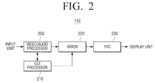
- FIG. 2 is a block diagram illustrating the image processor 110 of FIG. 1
- FIG. 3 is a block diagram illustrating a video/audio processor of FIG. 2 .
- the image processor 110 illustrated in FIG. 2 will be described, for example, under the assumption that the image input unit 100 of FIG. 1 directly receives a broadcast signal from a broadcasting station or the image input unit 100 is directly connected to a VCR or a camcorder.
- the image processor 110 of FIG. 1 may partially or entirely include a video/audio processor 200, a GUI processor 210, a mixer 220, and a frame rate controller (FRC) 230.
- phase may mean that the image processor 110 is configured to allow some components such as the mixer 220 and the FRC 230 to be omitted or allow some components such as the mixer 220 are integrated with other components such as the FRC 230.
- the image processor will be described to include all components in the embodiment.
- the video/audio processor 200 may have a configuration to process a radio frequency (RF) signal and a configuration to process a high-definition multimedia interface (HDMI) signal as illustrated in FIG. 3 .
- the video/audio processor 200 may partially or entirely include a tuner/demultiplexer (DMUX) 301, a decoder 303, a first scaler 305, and a first processor 307 which perform operations such as tuning, demultipexing, decoding, or scaling, and in response to the HDMI signal, the video/audio processor 200 may partially or entirely include a HDMI receiver (Rx) 311, a second scaler 313, and a second processor 315 which perform operations such as reception of the HDMI signal, or scaling of the received HDMI signal.
- DMUX tuner/demultiplexer
- Rx HDMI receiver
- second scaler 313 a second processor 315
- the tuner/DEMUX 301 selects a channel desired by the user, divides video and audio signals of the selected channel, and outputs the divided video and audio signals.
- the decoder 303 decodes an input encoded signal and outputs the decoded signal to the first scaler 305.
- the first scaler 305 may perform an operation, for example, such as bit conversion of an 8-bit video signal.
- the first processor 307 controls the first scaler 305 to output a scaled signal.
- the HDMI Rx 311 receives the HDMI signal
- the second scaler 313 scales a signal provided from the HDMI Rx 311, and the second processor 315 controls the second scaler 313 to output the scaled HDMI signal.
- the GUI processor 210 operates under two conditions. In other words, in response to no-change or lack of the image output method, the GUI processor 210 generates a GUI image and provides the generated GUI image to the mixer 220 to display the GUI image, such as a menu screen, together with the image processed in the video/audio processor 200. In response to a change of the image output method, the GUI processor 210 acquires at least one unit frame image processed in the video/audio processor 200 just before the start of the change of the image output method and uses the acquired unit frame image as the GUI image.
- the using of the GUI image means to process the acquired image and output the processed image. For example, in response to processing one unit frame image, the GUI processor may directly provide the acquired image as the GUI image to the mixer 220.
- the GUI processor may process the acquired image to add the animation effect. Further, the GUI processor 210 may generate the plurality of unit frame images by slightly shifting the acquired one unit frame image using the acquired one unit frame image. Here, the plurality of unit frame images may be processed and generated through adjustment in a size of the GUI image occupied in the screen.
- the mixer 220 may mix the video image provided from the video/audio processor 200 with the GUI image processed in the GUI processor 210.
- the mixing means that a background image, a video image, and a GUI image located in different layers are overlaid with each other.
- the video image in a second layer is overlaid on the background image located in a first layer
- the GUI image in a third layer is overlaid on the video image again. Therefore, a region other than a portion in which the images are displayed may be transparently processed.
- the GUI image may be a menu screen generated in the GUI processor 210.
- the GUI image may be an image acquired in the video/audio processor 200 in response to change of the image output method, that is, just before the change of the image output method, a processed image of the acquired image, or a newly generated image.
- the mixer 220 may sufficiently mix images in a single layer, and thus the embodiments are not limited thereto.
- the FRC 230 converts a frame rate of an input image and outputs the conversion result.
- the frame rate may be changed by a separate request of the user or based on an image analysis performed in the video/audio processor 200 under control of the video/audio processor 200.
- the FRC 230 may automatically convert the frame rate of the input image based on the frame rate of the display unit 120. For example, under the assumption that a moving image is reproduced, the frame rate of the image in the FRC 230 may be reduced in response to repetition of a still image as an analysis result of the plurality of input unit frame images in the video/audio processor 200.
- the frame rate of the image in the FRC 230 may be increased.
- the change of the frame rate may be also included in the change of the image output method.
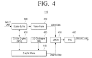
- FIG. 4 is a block diagram illustrating the image processor of FIG. 1 according to another exemplary embodiment.
- the image processor 110 of the image display apparatus 90 connected to an image reception apparatus such as a settop box is assumed.
- the image processor 110 may partially or entirely include a scaler/buffer 400, a video plane 410, a 3D engine unit 420, a 2D engine unit 430, a graphic plane 440, a mixer 450, and an FRC 460.
- the phrase "partially or entirely include” has the same meaning as the above-described phrase.
- the scaler/buffer 400 may perform a bit conversion operation such as scaling of an image of an image signal input through the image input unit 100 of FIG. 1 , and the scaled image data may be temporarily stored in and then output from the buffer.
- the bit conversion indicates, for example, a process such as conversion of 8-bit R, G, and B data to 6-bit R, G, and B data to represent or produce a resolution suitable for the display unit 120 of FIG. 1 .
- the video plane 410 may correspond to a kind of processor (or a controller). Merely, the video plane 410 may be slightly different from the processor in that software (S/W) or an application stored in an internal memory is executed to execute a specific operation.
- the video plane 410 controls the scaler/buffer 400 to output scaled image data to the mixer 450. At this time, the image data may be provided in frame units. Further, the video plane 410 may be involved in image generation.
- the video plane 410 may include an image generation unit (not shown) configured to generate a 3D image therein or may be interlocked with an image generation unit (not shown) located outside the video plane 410.
- the video plane 410 may analyze the input image signal and obtain information for a frame rate of a specific image. Then, the corresponding information may be transferred to the FRC 460.
- the video plane 410 may be variously modified. However, the modification may be specifically limited in the exemplary embodiment.
- the 3D engine unit 420 and the 2D engine unit 430 are involved in processing a menu screen in a 2D or 3D graphic. To this end, the 3D engine unit 420 and the 2D engine unit 430 may execute applications stored therein. In other words, the 3D engine unit 420 and the 2D engine unit 430 operate according to whether a 2D image or a 3D image is displayed on a screen of the display unit 120 (see FIG. 1 ), and output a generated graphic, for example, a menu screen.
- FIG. 4 illustrates, as one example, that the 3D engine unit 420 is connected to the scaler/buffer 400.
- At least one of the 3D engine unit 420 and the 2D engine unit 430 may acquire an image just before the change of the image output method from the scaler/buffer 400, and use the acquired image.
- the acquired image is provided to the mixer 450 under control of the graphic plane 440 directly or through a separate processing process.
- the separate process means a process of adding an animation effect.
- the graphic plane 440 is also a kind of processor like the video plane 410, and may control the 3D engine unit 420 or the 2D engine unit 430 according to whether the 2D image or the 3D image is displayed on the screen of the display unit 120. Further, the graphic plane 440 receives a graphic generated in the 3D engine unit 420 or the 2D engine unit 430 and provides the graphic to the mixer 450.
- the mixer 450 mixes video data provided from the video plane 410 with graphic data provided from the graphic plane 460 and provides the mixed image to the FRC 440.
- the FRC 460 converts the mixed image to a frame rate suitable for the display unit 120 of FIG. 1 and outputs a conversion result.
- the image display apparatus 90 may remove a need for a panel mute, for example, through the use of a graphic engine mounted as one module of a digital television (DTV) even in response to change of the image output method.
- DTV digital television
- the user since the mute does not exist, and a black screen which causes flicker in the related art is not viewed to the user, the user may watch a clean or noise free screen.
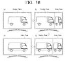
- FIGS. 5A and 5B are views comparatively illustrating implementation states of screens in the related art and the exemplary embodiment.
- a black screen may be inserted in the image output method changing process as illustrated in FIG. 5A (b) .
- an image to which an animation effect is added may be output in the image output method changing process as illustrated in FIGS. 5A (b) and (c) .
- an image corresponding to approximately an intermediate point of time between the beginning of the change of the image output method and the completion of the change of the image output method may be output and naturalness may be added to a change in the screen without addition of the animation effect.
- the user may recognize a screen change state of the screen, that is, a transient state through generation of the black screen as illustrated in FIG. 5A .
- the user may not recognize the transient state due to the natural change of the screen in FIG. 5B .
- the image processing method of adding the animation effect is presented as the preferred embodiment, but the embodiments are not limited thereto.
- FIGS. 5B (b) and (c) illustrate that only two unit frames are used, but the use of the unit frame may be variously changed.
- the display unit 120 displays an image of 50 frames per 1 second on the screen. Therefore, an initial image may be included between FIGS. 5B (a) and (d) , and 49 unit frame images other than a last image may be displayed.
- images corresponding to video planes in FIGS. 5B (b) and (c) may be 2D images, and images corresponding to graphic planes of an upper-side layer thereof may be gradually reduced in size.
- the images corresponding to the video planes in FIGS. 5B (b) and (c) may be a left-eye image and a right-eye image, and the sizes of the images corresponding to the graphic planes of the upper-side layer thereof may be gradually reduced while the left-eye image and the right-eye image are alternately output.
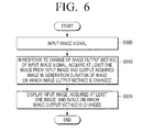
- FIG. 6 is a flowchart illustrating a driving process of an image display apparatus according to an exemplary embodiment.
- the image display apparatus 90 receives an image signal from a broadcasting station or a peripheral apparatus such as a VCR or a camcorder (S600).
- a peripheral apparatus such as a VCR or a camcorder (S600).
- the image display apparatus 90 In response to a change of an image output method of images of the input image signal, the image display apparatus 90 acquires at least one image from the images of the input image signal and outputs the acquired image in a generation duration of an image of which the image output method is changed (S610).
- the acquired at least one image corresponds to an image before the change of the image output method
- the generation duration of the image of which the image output method is changed means a time duration from a point of time at which the image changed according to the change of the image output method starts to be generated to a point of time at which generation of an image changed to first display the image on the screen is completed.
- the points of time are not limited thereto.
- the request time may be a start point of time
- a point of time in which the image output method is changed by analyzing an image format may be a start point of time.
- the completion point of time may not be a point of time in which an image to be first displayed on the screen is generated but a point of time in which all the plurality of unit frame images are generated according to a preset value.
- a point of time in which a new image, of which an image output method is changed, is output after the plurality of generated unit frame images are displayed may be determined as the completion point of time.
- the image display apparatus 90 displays the input image, the acquired at least one image, and the image of which the image output method is changed on a screen (S620).
- the image display apparatus 90 directly outputs the input image to the screen in response to non-change of the image output method, and the image display apparatus 90 outputs the at least one image acquired at a corresponding point of time and simultaneously displays the image of which the image output method is changed in response to change of the image output method.
- an animation effect may be added to the at least one image, and the image to which the animation effect is added may output so that a size of an image acquired and output at a point of time in which the image output method is changed is gradually reduced, and a size of a new image of which the image output method is changed is gradually increased.
- FIG. 7 is a flowchart illustrating an image display method according to an exemplary embodiment.
- the image display apparatus 90 outputs an input video image in real time (S700).
- the input video image may be a 2D image or a 3D image, but in the exemplary embodiment, the input video image may be the 2D image.
- the image display apparatus 90 determines whether or not an output method of the input video image is changed. To this end, the image display apparatus 90 may determine whether or not the user separately requests the change of the image output method, and analyze a format of the input video image. At this time, the analysis of the image format may be performed in response to change of a program or periodically at certain time intervals.
- the format of the 3D image includes side by side, top and bottom, frame packing, or the like.
- the image display apparatus 90 In response to a change of the image output method, the image display apparatus 90 outputs the input video image to the graphic plane 440 using a graphic engine (S720).
- the process corresponds to a process of acquiring an image from the input video image and first outputting the acquired image.
- the image display apparatus 90 determines whether or not the change of the image output method is completed (S730). For example, to output a 2D image as a 3D image, the image display apparatus 90 determines a point of time in which a pair of left-eye image and right-eye image are first generated and determines whether or not the change of the image output method is completed. Alternatively, the image display apparatus 90 may determine a point of time in which a unit frame image is generated to be suitable for a frame rate of the display unit 120 by a preset value as the completion point of time.
- the image display apparatus 90 may output an acquired image by selecting one of a plurality of frame images acquired at the beginning of the change of the image output method.
- the image display apparatus 90 may provide a unit frame image generated by slightly shifting the unit frame image acquired at the beginning of the change of the image output method until the change of the image output method is completed, to the graphic plane 440 as a GUI image.
- the image display apparatus 90 outputs the video image of the video plane 410 and the GUI image of the graphic plane 440 to a screen while the image display apparatus mutually change sizes (grows/shrinks) of the video image of the video plane 410 and the GUI image of the graphic plane 440 (S740). For example, in one screen, the size of the GUI image is gradually reduced or shrinks, and the size of the newly generated video image is gradually increased or grows.
- the image display apparatus 90 may repeat operation S740. However, in response to only both the left-eye video image and the right-eye video image being output (or generated), the image display apparatus 90 may additionally convert frame rates of the video data and the graphic data and output a conversion result (S750 and S760).
- the generation is described only in terms of the mixer 220 of FIG. 2 .
- the image display apparatus 90 outputs the input video image in real time. At this time, in response to a non-change of the output method of the input video image, the image display apparatus 90 converts the input video image to be suitable for the frame rate of the display unit 120 and outputs a conversion result.
- the image display apparatus 90 may acquire at least one image from the input video image using the graphic engine until the change of the input output method is completed and output the acquired image as the GUI image, or output the GUI images newly generated by adding the animation effect using the acquired image.
- the image display apparatus 90 may determine that the change of the image output method is completed in response to outputting the image in which the image output method is changed, for example, both the left-eye image and the right-eye image for a 3D implementation, and then interrupt the output of the GUI image.
- the image display apparatus 90 may output only the image of which the image output method is changed. Further, in response to the graphic data, such as a menu screen, the image display apparatus 90 may mix the image of which the image output method is changed with the graphic data and output a mixing result, and further the display apparatus 90 may convert the frame rate of the mixed image and output a conversion result.
- operations S730 and S750 in FIG. 7 may be understood as the same concept.
- operations S730 and S750 may have a difference in that operation S730 may be determined according to whether the initial image of which the image output method is changed is generated or whether or not the image is generated by a number of frames preset according to a intention of a system designer, and operation S750 may be determined according to the point of time in which only the initial image, of which the image output method is finally changed through addition of the animation effect, is generated or the point of time in which the initial image is displayed on the screen.
- the embodiments are not limited thereto.
- the operations are common in that the GUI image is displayed on the screen of the display unit 120 at a point of time in which the image output method is changed.
- some embodiments of the invention provide an apparatus for displaying an image, the apparatus comprising: an image input unit configured to allow an image signal to be input; an image processor configured to process an input image signal; and a display unit configured to display a processed image signal, wherein the image processor is arranged to, when the image output method of the input image signal is changed, acquire at least one image from the input image (e.g. at least one image according to the previous image output method) and to output the acquired image during a generation duration of an image of which an image output method is changed (e.g. while an image according to the new image output method is generated).
- the image processor is arranged to, when the image output method of the input image signal is changed, acquire at least one image from the input image (e.g. at least one image according to the previous image output method) and to output the acquired image during a generation duration of an image of which an image output method is changed (e.g. while an image according to the new image output method is generated).
- the image processor on detection of a change in image output method of the input image signal, is arranged to acquire an image (e.g. an image before the change in image output method) and to display this acquired image while an image according to the new image output method is generated.
- an animation effect may be added to the acquired image.
- the embodiments are not limited thereto. That is, even within the objection of the embodiments, at least two of the all the components may be selectively combined to operate. Further, all the components may be individually implemented in hardware, but the components may be implemented in a computer program having a program module in which partial or all components are selectively combined and one piece of computer hardware or a plurality of pieces of computer hardware performs portions of combined functions or all the combined functions. Codes and code segments constituting the computer program may be easily inferred by those skilled in the art.
- the computer program may be stored in non-transitory computer readable media, and read and executed by a computer so that the exemplary embodiment may be implemented.
- the non-transitory computer-recordable medium is not a medium configured to temporarily store data such as a register, a cache, or a memory but an apparatus-readable medium configured to semi-permanently store data.
- the programs may be stored in the non-transitory apparatus-readable medium such as a compact disc (CD), a digital versatile disc (DVD), a hard disc, a Blu-ray disc, a universal serial bus (USB), a memory card, or a read only memory (ROM), and provided.
Landscapes
- Engineering & Computer Science (AREA)
- Multimedia (AREA)
- Signal Processing (AREA)
- Human Computer Interaction (AREA)
- Controls And Circuits For Display Device (AREA)
- Processing Or Creating Images (AREA)
Applications Claiming Priority (1)
| Application Number | Priority Date | Filing Date | Title |
|---|---|---|---|
| KR1020140001425A KR102176474B1 (ko) | 2014-01-06 | 2014-01-06 | 영상표시장치, 영상표시장치의 구동방법 및 영상표시방법 |
Publications (1)
| Publication Number | Publication Date |
|---|---|
| EP2897362A1 true EP2897362A1 (fr) | 2015-07-22 |
Family
ID=51260634
Family Applications (1)
| Application Number | Title | Priority Date | Filing Date |
|---|---|---|---|
| EP14179003.0A Withdrawn EP2897362A1 (fr) | 2014-01-06 | 2014-07-29 | Appareil d'affichage d'image, procédé de commande associé et procédé pour afficher une image |
Country Status (3)
| Country | Link |
|---|---|
| US (1) | US10080014B2 (fr) |
| EP (1) | EP2897362A1 (fr) |
| KR (1) | KR102176474B1 (fr) |
Cited By (1)
| Publication number | Priority date | Publication date | Assignee | Title |
|---|---|---|---|---|
| CN105554562A (zh) * | 2015-12-10 | 2016-05-04 | 天脉聚源(北京)传媒科技有限公司 | 一种图像显示方法及装置 |
Families Citing this family (4)
| Publication number | Priority date | Publication date | Assignee | Title |
|---|---|---|---|---|
| US9294752B2 (en) * | 2011-07-13 | 2016-03-22 | Google Technology Holdings LLC | Dual mode user interface system and method for 3D video |
| KR102486797B1 (ko) * | 2016-03-09 | 2023-01-11 | 삼성전자 주식회사 | 전자 장치 및 전자 장치의 디스플레이 구동 방법 |
| US10223060B2 (en) * | 2016-08-22 | 2019-03-05 | Google Llc | Interactive video multi-screen experience on mobile phones |
| KR102724428B1 (ko) * | 2019-12-12 | 2024-11-01 | 삼성전자주식회사 | 디스플레이 장치 및 그 동작 방법 |
Citations (3)
| Publication number | Priority date | Publication date | Assignee | Title |
|---|---|---|---|---|
| EP1628490A1 (fr) * | 2003-05-27 | 2006-02-22 | Sanyo Electric Co., Ltd. | Dispositif et programme d'affichage d'images |
| US20070058933A1 (en) * | 2005-09-12 | 2007-03-15 | Sony Corporation | Reproducing apparatus, reproducing method, program, and program storage medium |
| EP2464126A1 (fr) * | 2010-12-10 | 2012-06-13 | Advanced Digital Broadcast S.A. | Système et procédé de transformation d'une séquence vidéo en 3D en séquence vidéo en 2D |
Family Cites Families (7)
| Publication number | Priority date | Publication date | Assignee | Title |
|---|---|---|---|---|
| JP2011114863A (ja) * | 2009-11-23 | 2011-06-09 | Samsung Electronics Co Ltd | 3D映像の提供方法、3D映像の変換方法、GUI提供方法及びこれを適用した3Dディスプレイ装置、そして3D映像の提供システム{Methodforproviding3Dimage、methodforconverting3Dimage、GUIprovidingmethodrelatedto3Dimageand3Ddisplayapparatusandsystemforproviding3Dimage} |
| JP2011166666A (ja) * | 2010-02-15 | 2011-08-25 | Sony Corp | 画像処理装置、画像処理方法およびプログラム |
| KR20120034574A (ko) * | 2010-10-01 | 2012-04-12 | 삼성전자주식회사 | 디스플레이 장치 및 신호 처리 장치와, 그 방법들 |
| KR20120034996A (ko) * | 2010-10-04 | 2012-04-13 | 엘지전자 주식회사 | 영상표시장치 및 그 동작방법 |
| US20130258073A1 (en) * | 2010-12-06 | 2013-10-03 | Dolby Laboratories Licensing Corporation | Methods and apparatus for image adjustment for displays having 2d and 3d display modes |
| JP4892098B1 (ja) * | 2010-12-14 | 2012-03-07 | 株式会社東芝 | 立体映像表示装置及び方法 |
| KR20120117578A (ko) * | 2011-04-15 | 2012-10-24 | 삼성전자주식회사 | 디스플레이 방법 및 이를 적용한 디스플레이 장치 |
-
2014
- 2014-01-06 KR KR1020140001425A patent/KR102176474B1/ko not_active Expired - Fee Related
- 2014-07-07 US US14/324,576 patent/US10080014B2/en active Active
- 2014-07-29 EP EP14179003.0A patent/EP2897362A1/fr not_active Withdrawn
Patent Citations (3)
| Publication number | Priority date | Publication date | Assignee | Title |
|---|---|---|---|---|
| EP1628490A1 (fr) * | 2003-05-27 | 2006-02-22 | Sanyo Electric Co., Ltd. | Dispositif et programme d'affichage d'images |
| US20070058933A1 (en) * | 2005-09-12 | 2007-03-15 | Sony Corporation | Reproducing apparatus, reproducing method, program, and program storage medium |
| EP2464126A1 (fr) * | 2010-12-10 | 2012-06-13 | Advanced Digital Broadcast S.A. | Système et procédé de transformation d'une séquence vidéo en 3D en séquence vidéo en 2D |
Cited By (1)
| Publication number | Priority date | Publication date | Assignee | Title |
|---|---|---|---|---|
| CN105554562A (zh) * | 2015-12-10 | 2016-05-04 | 天脉聚源(北京)传媒科技有限公司 | 一种图像显示方法及装置 |
Also Published As
| Publication number | Publication date |
|---|---|
| US20150195514A1 (en) | 2015-07-09 |
| US10080014B2 (en) | 2018-09-18 |
| KR20150081687A (ko) | 2015-07-15 |
| KR102176474B1 (ko) | 2020-11-09 |
Similar Documents
| Publication | Publication Date | Title |
|---|---|---|
| US11146737B2 (en) | Video display system and video display method | |
| JP2011507415A (ja) | ビデオ送信側装置及びビデオ受信側装置を有するシステムにおけるビデオ処理の調整 | |
| KR100860174B1 (ko) | 영상 표시 장치 및 그 운용방법 | |
| EP2895947B1 (fr) | Poste de télévision capable d'identifier une pluralité de périphériques et permettant de sélectionner et d'afficher le contenu d'un d'entre eux | |
| EP2429197B1 (fr) | Procédé et système pour générer un signal pour unité d'affichage vidéo | |
| US10080014B2 (en) | Apparatus for displaying image, driving method thereof, and method for displaying image that allows a screen to be naturally changed in response to displaying an image by changing a two-dimensional image method to a three-dimensional image method | |
| EP3603059B1 (fr) | Diagnostics d'affichage pour améliorer les performances des dispositifs d'affichage | |
| US7324742B2 (en) | Video-signal processing apparatus and method, recording medium and program | |
| JP6151010B2 (ja) | 情報処理装置および表示制御方法 | |
| KR100587614B1 (ko) | 디지털 방송 수신기 및 방송 신호 디스플레이 방법 | |
| JP2007139866A (ja) | 映像信号処理システム | |
| EP1662780A2 (fr) | Appareil et procédé d'affichage | |
| US20250219811A1 (en) | Interface device and image display apparatus including the same | |
| KR20090030530A (ko) | 고해상도 그래픽 화면을 전송하기 위한 영상처리기기 및영상처리방법 | |
| KR100531311B1 (ko) | 멀티 패스를 갖는 osd의 구현 방법 | |
| US10341600B2 (en) | Circuit applied to television and associated image display method | |
| JP2006033253A (ja) | デジタルtv受信装置、デジタルtv受信方法、及びデジタルtv受信プログラム | |
| KR100917480B1 (ko) | 디지털 방송 수신기 및 데이터 신호 처리 방법 | |
| KR101299454B1 (ko) | 디스플레이장치 및 그 정보저장방법 | |
| KR100557545B1 (ko) | 디지털 방송 수신기에서 방송 신호 디스플레이 방법 | |
| KR102226136B1 (ko) | 영상표시장치 및 그 동작방법 | |
| JP2014187480A (ja) | 画像処理装置、ソース機器、画像処理システム、画像処理方法およびプログラム | |
| KR20070120304A (ko) | 수평확장이 가능한 영상재생장치 및 방법 | |
| US20140146135A1 (en) | Image processing apparatus and image processing method | |
| JP2008160553A (ja) | デジタル放送受信装置およびそれを備えた画像表示装置 |
Legal Events
| Date | Code | Title | Description |
|---|---|---|---|
| PUAI | Public reference made under article 153(3) epc to a published international application that has entered the european phase |
Free format text: ORIGINAL CODE: 0009012 |
|
| 17P | Request for examination filed |
Effective date: 20140729 |
|
| AK | Designated contracting states |
Kind code of ref document: A1 Designated state(s): AL AT BE BG CH CY CZ DE DK EE ES FI FR GB GR HR HU IE IS IT LI LT LU LV MC MK MT NL NO PL PT RO RS SE SI SK SM TR |
|
| AX | Request for extension of the european patent |
Extension state: BA ME |
|
| 17P | Request for examination filed |
Effective date: 20160122 |
|
| RBV | Designated contracting states (corrected) |
Designated state(s): AL AT BE BG CH CY CZ DE DK EE ES FI FR GB GR HR HU IE IS IT LI LT LU LV MC MK MT NL NO PL PT RO RS SE SI SK SM TR |
|
| STAA | Information on the status of an ep patent application or granted ep patent |
Free format text: STATUS: EXAMINATION IS IN PROGRESS |
|
| 17Q | First examination report despatched |
Effective date: 20180717 |
|
| STAA | Information on the status of an ep patent application or granted ep patent |
Free format text: STATUS: THE APPLICATION IS DEEMED TO BE WITHDRAWN |
|
| 18D | Application deemed to be withdrawn |
Effective date: 20220629 |