EP2897384A2 - Procédé et appareil de rendu audio dans des prothèses auditives sans fil - Google Patents
Procédé et appareil de rendu audio dans des prothèses auditives sans fil Download PDFInfo
- Publication number
- EP2897384A2 EP2897384A2 EP15151348.8A EP15151348A EP2897384A2 EP 2897384 A2 EP2897384 A2 EP 2897384A2 EP 15151348 A EP15151348 A EP 15151348A EP 2897384 A2 EP2897384 A2 EP 2897384A2
- Authority
- EP
- European Patent Office
- Prior art keywords
- audio
- packet
- hearing assistance
- assistance device
- sample clock
- Prior art date
- Legal status (The legal status is an assumption and is not a legal conclusion. Google has not performed a legal analysis and makes no representation as to the accuracy of the status listed.)
- Granted
Links
Images


Classifications
-
- H—ELECTRICITY
- H04—ELECTRIC COMMUNICATION TECHNIQUE
- H04R—LOUDSPEAKERS, MICROPHONES, GRAMOPHONE PICK-UPS OR LIKE ACOUSTIC ELECTROMECHANICAL TRANSDUCERS; ELECTRIC HEARING AIDS; PUBLIC ADDRESS SYSTEMS
- H04R25/00—Electric hearing aids
- H04R25/55—Electric hearing aids using an external connection, either wireless or wired
- H04R25/554—Electric hearing aids using an external connection, either wireless or wired using a wireless connection, e.g. between microphone and amplifier or using Tcoils
-
- H—ELECTRICITY
- H04—ELECTRIC COMMUNICATION TECHNIQUE
- H04W—WIRELESS COMMUNICATION NETWORKS
- H04W56/00—Synchronisation arrangements
- H04W56/001—Synchronization between nodes
- H04W56/002—Mutual synchronization
-
- H—ELECTRICITY
- H04—ELECTRIC COMMUNICATION TECHNIQUE
- H04R—LOUDSPEAKERS, MICROPHONES, GRAMOPHONE PICK-UPS OR LIKE ACOUSTIC ELECTROMECHANICAL TRANSDUCERS; ELECTRIC HEARING AIDS; PUBLIC ADDRESS SYSTEMS
- H04R25/00—Electric hearing aids
- H04R25/55—Electric hearing aids using an external connection, either wireless or wired
- H04R25/552—Binaural
-
- H—ELECTRICITY
- H04—ELECTRIC COMMUNICATION TECHNIQUE
- H04W—WIRELESS COMMUNICATION NETWORKS
- H04W4/00—Services specially adapted for wireless communication networks; Facilities therefor
- H04W4/80—Services using short range communication, e.g. near-field communication [NFC], radio-frequency identification [RFID] or low energy communication
-
- H—ELECTRICITY
- H04—ELECTRIC COMMUNICATION TECHNIQUE
- H04R—LOUDSPEAKERS, MICROPHONES, GRAMOPHONE PICK-UPS OR LIKE ACOUSTIC ELECTROMECHANICAL TRANSDUCERS; ELECTRIC HEARING AIDS; PUBLIC ADDRESS SYSTEMS
- H04R2225/00—Details of deaf aids covered by H04R25/00, not provided for in any of its subgroups
- H04R2225/55—Communication between hearing aids and external devices via a network for data exchange
Definitions
- This document relates generally to audio systems and more particularly to a method and apparatus for rendering audio in one or more hearing instruments coupled to an audio source via a wireless communication link.
- One or more hearing instruments may be worn on one or both sides of a person's head to deliver sounds to the person's ear(s).
- An example of such hearing instruments includes a pair of hearing aids that are used to assist a patient suffering hearing loss by transmitting amplified sounds to ear canals.
- the one or more hearing instruments receive audio from an audio source via a wireless communication link. To ensure quality of the sound delivered to the person's ear(s), there is a need to coordinate the one or more hearing instruments for processing the wirelessly received audio under various practical conditions.
- An audio system such as a hearing assistance system includes an audio source device wirelessly communicating with one or more audio sink (destination) devices.
- the audio source and sink devices each include a sample clock for processing audio signal that is digitized and wirelessly transmitted.
- the sample clock of each of the one or more audio sink devices is synchronized to the sample clock of the audio source device to prevent audio sample over-runs or under-runs causing undesirable audio artifacts.
- packet loss concealment techniques are used to improve audio reproduction.
- link layer information is used for audio phase lock loop jitter reduction in the audio system.
- the present document discusses an audio system, such as a hearing assistance system, that includes an audio source device wirelessly communicating with one or more audio sink (destination) devices.
- the audio source and sink devices each include a sample clock for acoustic signal processing.
- the sample clock of each of the one or more audio sink devices is synchronized to the sample clock of the audio source device to prevent audio sample over-runs or under-runs causing undesirable audio artifacts.
- packet loss concealment techniques are used to improve audio reproduction.
- the sample clock of an audio sink device is synchronized to the sample clock of an audio source device using a radio employing a packet based method of transmission based on a receive time slot.
- the synchronization is maintained by timing the arrival of an audio packet using an adjustable oscillator and making adjustments to that oscillator.
- the adjustable oscillator includes an RC type oscillator with an adjustable resistance or capacitance, a voltage-controlled oscillator (VCO), a current-controlled oscillator (ICO), or a digital numerically controlled oscillator.
- the link layer of a radio is used to determine when a packet is missed, sent with errors or is empty, thereby aiding the signal processor of an audio sink device in maintaining accurate synchronization using an adjustable oscillator.
- the adjustable oscillator includes an RC type oscillator with an adjustable resistance or capacitance, a VCO, an ICO, or a digital numerically controlled oscillator.
- the link layer of a radio is used to determine when a packet is missed, sent with errors or is empty for the purpose of employing a packet loss concealment strategy for the missing, empty, or packet received in error.
- the link layer of a radio is used to determine whether a packet received was on the primary transmission or on one of multiple retransmission attempts, thus allowing successful maintenance of an output sample rate regardless of the arrival time of the packet and on which retransmission a successful reception took place.
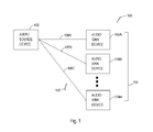
- FIG. 1 is a block diagram illustrating an embodiment of an audio system 100 including an audio source device 102, audio sink devices 104, and a wireless communication network 106.
- audio sink devices 104 includes audio sink device 104A coupled to audio source device 102 via wireless communication link 106A, audio sink device 104B coupled to audio source device 102 via wireless communication link 106B, ... , audio sink device 104N coupled to audio source device 102 via wireless communication link 106N.
- N is an integer equal to or greater than 1.
- audio sink devices 104 include a hearing instrument configured to be worn by a person (hearing instrument wearer) to deliver sound to that person. Audio source devices 102 transmits an acoustic signal to each of audio sink device 104A-N via wireless communication link 106A-N, such as a Bluetooth® link, respectively.
- Modern hearing instruments employ digital processing techniques to enhance the intelligibility of incoming acoustic information for the hearing instrument wearer.
- modern hearing instruments have wireless connectivity to audio sources such as cellphones, computers including desktop, laptop, and tablet computers, and other devices that can send and receive digital audio information.
- Other devices such as wireless headphones process digital audio information in a similar manner.
- Most wireless standards such as Bluetooth employ audio compressor-decompressors (CODECs) to compress audio information before sending it over the air to limit the amount of data to be sent wirelessly to remote audio sink devices and to enhance the performance of the wireless link.
- CDECs audio compressor-decompressors
- wireless audio sink devices In order for the wireless audio sink devices receiving the information to playback the transmitted information without unwanted audio artifacts, such devices employ digital and analog techniques to synchronize the output sample clock with the input sample clock at the audio source device. In addition, these wireless audio sink devices must cope with the possibility that the transmitted information may be lost in the wireless communication link due to interference, multipath fading, and/or the like. To improve synchronization, several techniques such as digital multi-rate filtering, clock tracking, packet loss concealment and the like are employed. Digital techniques may require significant over sampling or resampling based on polyphase multi-rate filtering techniques to achieve "artifact free" audio playback.
- audio sink devices 104 include hearing aids
- the hearing instrument wearer uses two hearing instruments each rendering left and right audio channels independently. To maintain a comfortable listening environment it is essential that these two channels are rendered coherent with each other within a small timing offset. This further increases the need for audio sample accuracy between the two independent audio sink devices.
- audio source device 100 and audio sink devices 104 each include a sample clock for processing audio signal that is digitized and transmitted via wireless communication network 106.
- the sample clock of each of audio sink devices 104A-N is synchronized to the sample clock of the audio source device 102 to prevent audio sample over-runs or under-runs causing undesirable audio artifacts.
- packet loss concealment techniques are used to improve audio reproduction.
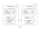
- FIG. 2 is a block diagram illustrating an embodiment of an audio system 200 including an audio source device 202 and an audio sink device 204.
- System 200 represents an example of system 100 for the purpose of illustrating portions of a circuit of audio source and sink devices.
- Audio source device 202 represents an example of audio source device 102.
- Audio sink device 204 represents an example of one of audio sink devices 104A-N. While one pair of audio source and sink devices is illustrated in FIG. 2 , system 200 may include two or more audio sink devices each operating as discussed for audio sink device 204.
- the portions of the circuit of audio source device 202 include a processing circuit 212 and a wireless communication circuit 214.
- the processing circuit 212 is configured to process an acoustic signal for transmission to audio sink device 204 via wireless communication link 206 and includes an audio reference oscillator 222 and a sample clock 224. Sample clock 224 times the input sampling of the acoustic signal based on the frequency generated by audio reference oscillator 222.
- Wireless communication circuit 214 provides an interface to wireless communication link 206 and includes a radio circuit with a communication reference oscillator (also referred to as RF oscillator) 226 for generating an RF (radio frequency) signal for the wireless transmission of the digitized acoustic signal.
- RF oscillator also referred to as RF oscillator
- the portions of the circuit of audio sink device 204 include a processing circuit 216 and a wireless communication circuit 218.
- the processing circuit 216 is configured to process the acoustic signal transmitted from audio source device 202 via wireless communication link 206 and includes an audio reference oscillator 228 and a sample clock 230. Sample clock 230 times the output sampling of the acoustic signal based on the frequency generated by audio reference oscillator 228.
- Wireless communication circuit 218 provides an interface to wireless communication link 206 and includes a radio circuit a communication reference oscillator (also referred to as RF oscillator) 232 for demodulating the received acoustic signal.
- RF oscillator also referred to as RF oscillator
- processing circuit 216 includes a digital signal processor (DSP).
- DSPs digital signal processor
- Low power DSPs typically employ clock sources based on RC oscillators, voltage controlled oscillators (VCOs) and current controlled oscillators (ICOs).
- VCOs voltage controlled oscillators
- ICOs current controlled oscillators
- Such oscillators drive the system clocks on these DSPs and ultimately drive the output sample rate (from sample clock 230).
- Radios operating at high frequencies such as 2.4 GHz require much greater frequency stability and accuracy in order to perform successful over the air reception and transmission of data.
- Such devices use high accuracy frequency references such as crystal oscillators, resonators, or MEMS type oscillators.
- the DSP in a hearing instrument may, depending on the application, benefit from the addition of such accurate frequency references.
- crystal reference oscillators For both communication reference oscillator 232 and audio reference oscillator 228 may not be a practical solution to the problem of providing frequency stability and accuracy.
- sample clock 224 and communication reference oscillator 214 of audio source device 202 are not necessarily locked together, and sample clock 230 and communication reference oscillator 232 of audio sink device 204 are not necessarily locked together, either. Consequently, audio sink device 204 should make no assumption about the relationship between communication (RF) clock and audio clock in standardized communication such a Bluetooth.
- An audio source device may derive its sample rate from highly accurate reference such as crystal oscillators and the like but do not necessarily have their RF radio frequency and packet timing based on the same oscillator that the audio sample clock is derived from.
- audio sink device 204 can adjust its sample clock 230 based on time stamps between packet arrivals and the number of encoded words received in each incoming packet. Audio source device 202 may send a variable number of encoded words in each packet since the timing for the RF packet arrival is not synchronized with the audio encoder. Audio sink device 204, knowing how many system clock signals it should expect between packet arrivals when adjusted for the number of arrived encoded samples, can form an error signal that it can use to drive audio reference oscillator 228. In various embodiments, audio reference oscillator 228 includes an RC oscillator with an adjustable resistance or adjustable capacitance, a VCO, an ICO, or a digital numerically controlled oscillator, such that the output frequency is controllable using the error signal.
- system 200 uses communication reference oscillator 232 to "preposition" audio reference oscillator 228 prior to receiving any samples from audio source device 202.
- the DSP of processing circuit 216 can adjust its controllable audio reference oscillator 228 for a small PPM (parts per million) error in synchronizing to audio reference oscillator 222 of audio source device 202.
- synchronization may have to survive events such as lost packets while maintaining a close relationship between sample clocks 224 and 230.
- processing circuit 216 can be aided from the radio of wireless communication circuit 218 by being updated as to the status of a packet. This may include information from the radio as to whether a packet was empty, missed, or received with errors.
- Such link layer information can be sent through an interface between the radio of wireless communication circuit 218 and the DSP of processing circuit 216. The DSP can use this information to determine whether a packet loss concealment strategy should be employed to substitute the missing audio with silence, a previously received packet, or an interpolated packet based on linear prediction.
- this link layer information can be used to maintain the phase and frequency of sample clock 230.
- Packets may be resent from audio source device 202 in an effort to improve the overall packet error rate performance of wireless link 206. These retransmissions can happen as a result of audio source device failing to receive an acknowledgement from audio sink device 204, or they can be sent unconditionally with a number of retransmissions as in the case of a one way or broadcast mode of transmission. In this case, it will be necessary for the link layer to inform the DSP that the successful reception was on a retransmission that may take place at a different time interval from the primary transmission.
- the DSP can adapt its synchronization timer with information from the link layer of the radio informing the DSP as to which of the transmissions the packet was successfully received.
- the transmission may be successful on the primary transmission or on one of the retransmission attempts. Without knowing this information from the link layer, the phase and frequency lock may be disturbed since the time of arrival or the packet at the DSP is used as the error signal to maintain the output sample clock.
- the radio of wireless communication circuit 218 sends information to the DSP of processing circuit 216 that a packet was missing or was sent as an empty packet to allow the DSP to insert a packet loss concealment (PLC) frame of information. This may be silent packet, replay or Linear predicted frame based on previous frames.
- PLC packet loss concealment
- the radio is making this determination instead of relying on the DSP and its first-in-first-out (FIFO) pointer and crude RC timing to determine if a packet did not arrive.
- FIFO first-in-first-out
- the drawback is that it may require a higher sample rate and a multistage filter which require additional instructions or operations, thus increasing power consumption of the system.
- FIG. 3 is a block diagram illustrating an embodiment of a hearing assistance system 300.
- System 300 represents an example of system 100 or system 200 and includes a host device 302, a hearing assistance device 304, and communication link 206 providing for wireless communication between host device 302 and hearing assistance device 304.
- host device 302 and hearing assistance device 304 may each include one or more devices.
- host device 302 may include a computer or a computer connected to a communicator
- hearing assistance device 304 may include a single device or a pair of devices such as a pair of left and right hearing aids.
- host device 302 includes any device that transmits acoustic signals to hearing assistance device 304.
- Examples of host device 302 include a hearing aid programmer, a computer, phone, and any devices capable of streaming audio to hearing assistance device 304.
- communication link 206 includes a Bluetooth wireless connection.
- host device 302 includes an audio streaming device that streams audio to hearing assistance device 304.
- the audio streaming device include computer, television set, telephone, and any music or other audio player.
- host device 302 includes a user interface 310, a processing circuit 312, and a wireless communication circuit 314.
- user interface 310 includes a presentation device including at least a display screen and an input device.
- the presentation device may also include various audial and/or visual indicators, and the user input device may include a computer mouse, a touchpad, a trackball, a joystick, a keyboard, a keypad, and/or various forms of switches.
- user interface 310 includes an interactive screen such as a touchscreen functioning as both the presentation device and the input device.
- Processing circuit 312 represents an example of processing circuit 212 and is configured to perform various functions including those of processing circuit 212 as discussed in this document.
- Wireless communication circuit 314 represents an example of wireless communication circuit 214 and is configured to perform various functions including those of wireless communication circuit 214 as discussed in this document.
- Hearing assistance device 304 includes a processing circuit 316 and a communication circuit 318.
- Processing circuit 316 represents an example of processing circuit 216 and is configured to perform various functions including those of processing circuit 216 as discussed in this document.
- Wireless communication circuit 318 represents an example of wireless communication circuit 218 and is configured to perform various functions including those of wireless communication circuit 218 as discussed in this document.
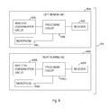
- FIG. 4 is a block diagram illustrating an embodiment of a pair of hearing aids 404 representing an example of hearing assistance device 304.
- Hearing aids 404 include a left hearing aid 404L and a right hearing aid 404R.
- Left hearing aid 404L includes a microphone 440L, a wireless communication circuit 418L, a processing circuit 416L, and a receiver (also known as a speaker) 442L.
- Microphone 440L receives sounds from the environment of the listener (hearing aid wearer).
- Wireless communication circuit 418L represents an example of wireless communication circuit 318 and wirelessly communicates with host device 302 and/or right hearing aid 404R, including receiving signals from host device 302 directly or through right hearing aid 404R.
- Processing circuit 416L represents an example of processing circuit 316 and processes the sounds received by microphone 440L and/or an audio signal received by wireless communication circuit 418L to produce a left output sound.
- Receiver 442L transmits the left output sound to the left ear canal of the listener.
- Right hearing aid 404R includes a microphone 440R, a wireless communication circuit 418R, a processing circuit 416R, and a receiver (also known as a speaker) 442R.
- Microphone 440R receives sounds from the environment of the listener.
- Wireless communication circuit 418R represents an example of communication circuit 318 and wirelessly communicates with host device 302 and/or left hearing aid 404L, including receiving signals from host device 302 directly or through left hearing aid 404L.
- Processing circuit 416R represents an example of processing circuit 316 and processes the sounds received by microphone 440R and/or an audio signal received by wireless communication circuit 418R to produce a right output sound.
- Receiver 442R transmits the right output sound to the right ear canal of the listener.
- link layer information is used by processing circuit 216 (including its various examples discussed in this document) for audio phase lock loop (PLL) jitter reduction in system 100 and its various embodiments such as those discussed in this document.
- PLL phase lock loop
- maintaining the phase between the transmit clock and the audio rendering clock is very important. Not only does it ensure high audio quality by keeping the audio FIFO at the receiver (such as one of audio sink devices 104 including its various examples discussed in this document) at a suitable depth, but it also guarantees a defined phase difference between two decoders in a wireless stereo system. Maintaining the phase difference between the two ears is extremely important in providing the user with a high degree of audio fidelity. Differential phase disturbance between the two ears is perceived as a spatial change in sound location which can be quite annoying.
- each audio packet is transmitted up to two times. If the first (primary) packet is not acknowledged by the receiver, then audio packet is sent again.
- the audio PLL measures the time of arrival of the audio packet and uses that as an "error" variable to control its timing loop.
- the PLL loop will see a train of clean timing events generated by primary packets. These can be used to control the timing loop as defined by a classic PLL.
- the clean timing signal is replaced with a signal which has the following elements added to it:
- Hearing assistance devices typically include an enclosure or housing, a microphone, hearing assistance device electronics including processing electronics, and a speaker or receiver. It is understood that in various embodiments the receiver is optional.
- Antenna configurations may vary and may be included within an enclosure for the electronics or be external to an enclosure for the electronics. Thus, the examples set forth herein are intended to be demonstrative and not a limiting or exhaustive depiction of variations.
- any hearing assistance device may be used without departing from the scope and the devices depicted in the figures are intended to demonstrate the subject matter, but not in a limited, exhaustive, or exclusive sense. It is also understood that the present subject matter can be used with a device designed for use in the right ear or the left ear or both ears of the wearer.
- processing circuit of the hearing aids referenced in this document may be a digital signal processor (DSP), microprocessor, microcontroller, other digital logic, or combinations thereof.
- DSP digital signal processor
- the processing of signals referenced in this application can be performed using the processing circuit. Processing may be done in the digital domain, the analog domain, or combinations thereof. Processing may be done using subband processing techniques. Processing may be done with frequency domain or time domain approaches. Some processing may involve both frequency and time domain aspects. For brevity, in some examples drawings may omit certain blocks that perform frequency synthesis, frequency analysis, analog-to-digital conversion, digital-to-analog conversion, amplification, audio decoding, and certain types of filtering and processing.
- the processor is adapted to perform instructions stored in memory which may or may not be explicitly shown.
- Various types of memory may be used, including volatile and nonvolatile forms of memory.
- instructions are performed by the processor to perform a number of signal processing tasks.
- analog components are in communication with the processor to perform signal tasks, such as microphone reception, or receiver sound embodiments (i.e., in applications where such transducers are used).
- signal tasks such as microphone reception, or receiver sound embodiments (i.e., in applications where such transducers are used).
- different realizations of the block diagrams, circuits, and processes set forth herein may occur without departing from the scope of the present subject matter.
- hearing assistance devices including hearing aids, including but not limited to, behind-the-ear (BTE), in-the-ear (ITE), in-the-canal (ITC), receiver-in-canal (RIC), invisible-in-the-canal (IIC) or completely-in-the-canal (CIC) type hearing aids.
- BTE behind-the-ear
- ITE in-the-ear
- ITC in-the-canal
- RIC receiver-in-canal
- IIC invisible-in-the-canal
- CIC completely-in-the-canal
- hearing assistance devices including but not limited to, behind-the-ear (BTE), in-the-ear (ITE), in-the-canal (ITC), receiver-in-canal (RIC), invisible-in-the-canal (IIC) or completely-in-the-canal (CIC) type hearing aids.
- BTE behind-the-ear
- ITE in-the-ear
- ITC in-the-canal
- RIC receiver-in
- the present subject matter can also be used in hearing assistance devices generally, such as cochlear implant type hearing devices and such as deep insertion devices having a transducer, such as a receiver or microphone, whether custom fitted, standard, open fitted or occlusive fitted. It is understood that other hearing assistance devices not expressly stated herein may be used in conjunction with the present subject matter.
Landscapes
- Engineering & Computer Science (AREA)
- Computer Networks & Wireless Communication (AREA)
- Signal Processing (AREA)
- Health & Medical Sciences (AREA)
- General Health & Medical Sciences (AREA)
- Neurosurgery (AREA)
- Otolaryngology (AREA)
- Physics & Mathematics (AREA)
- Acoustics & Sound (AREA)
- Circuit For Audible Band Transducer (AREA)
- Synchronisation In Digital Transmission Systems (AREA)
Applications Claiming Priority (2)
| Application Number | Priority Date | Filing Date | Title |
|---|---|---|---|
| US201461927669P | 2014-01-15 | 2014-01-15 | |
| US14/595,739 US9661425B2 (en) | 2014-01-15 | 2015-01-13 | Method and apparatus for rendering audio in wireless hearing instruments |
Publications (3)
| Publication Number | Publication Date |
|---|---|
| EP2897384A2 true EP2897384A2 (fr) | 2015-07-22 |
| EP2897384A3 EP2897384A3 (fr) | 2015-08-26 |
| EP2897384B1 EP2897384B1 (fr) | 2018-11-21 |
Family
ID=52465174
Family Applications (1)
| Application Number | Title | Priority Date | Filing Date |
|---|---|---|---|
| EP15151348.8A Active EP2897384B1 (fr) | 2014-01-15 | 2015-01-15 | Procédé et appareil de rendu audio dans des prothèses auditives sans fil |
Country Status (3)
| Country | Link |
|---|---|
| US (1) | US9661425B2 (fr) |
| EP (1) | EP2897384B1 (fr) |
| DK (1) | DK2897384T3 (fr) |
Cited By (9)
| Publication number | Priority date | Publication date | Assignee | Title |
|---|---|---|---|---|
| EP3139635A1 (fr) * | 2015-08-28 | 2017-03-08 | Alex Volkov | Synchronisation de trains de séquence audio et taux d'échantillonnage pour communication sans fil |
| US9819705B2 (en) | 2015-08-18 | 2017-11-14 | Gn Hearing A/S | Method of exchanging data packages between first and second portable communication devices using a favoured frequency band |
| US9831988B2 (en) | 2015-08-18 | 2017-11-28 | Gn Hearing A/S | Method of exchanging data packages between first and second portable communication devices |
| EP3255902A1 (fr) * | 2016-06-06 | 2017-12-13 | Starkey Laboratories, Inc. | Procédé et appareil pour améliorer l'intelligibilité de la parole dans des dispositifs auditifs au moyen de microphone à distance |
| US9894447B2 (en) | 2010-10-14 | 2018-02-13 | Gn Resound A/S | Hearing device and a method of selecting an optimal transceiver channel in a wireless network |
| US10003896B2 (en) | 2015-08-18 | 2018-06-19 | Gn Hearing A/S | Method of exchanging data packages of different sizes between first and second portable communication devices |
| EP3609207A1 (fr) * | 2018-08-07 | 2020-02-12 | GN Hearing A/S | Système de rendu audio |
| WO2021037681A1 (fr) * | 2019-08-23 | 2021-03-04 | Nordic Semiconductor Asa | Appareil radio pour communiquer des flux audio numériques |
| EP4109928A1 (fr) * | 2021-06-21 | 2022-12-28 | Sonova AG | Procédé et système de diffusion en continu d'un signal audio multicanal vers un système auditif binauriculaire |
Families Citing this family (10)
| Publication number | Priority date | Publication date | Assignee | Title |
|---|---|---|---|---|
| US10129839B2 (en) * | 2014-12-05 | 2018-11-13 | Qualcomm Incorporated | Techniques for synchronizing timing of wireless streaming transmissions to multiple sink devices |
| US9911433B2 (en) * | 2015-09-08 | 2018-03-06 | Bose Corporation | Wireless audio synchronization |
| US20170303062A1 (en) * | 2016-01-13 | 2017-10-19 | Xin Ren | Method for wirelessly synchronizing electronic devices |
| JP6900272B2 (ja) * | 2017-08-09 | 2021-07-07 | オムロンヘルスケア株式会社 | データ送信装置 |
| SG11202003199VA (en) | 2017-11-01 | 2020-05-28 | Razer Asia Pacific Pte Ltd | Method and apparatus for resampling audio signal |
| US10798498B2 (en) | 2018-10-30 | 2020-10-06 | Earlens Corporation | Rate matching algorithm and independent device synchronization |
| US10937433B2 (en) * | 2018-10-30 | 2021-03-02 | Earlens Corporation | Missing data packet compensation |
| CN112218197B (zh) * | 2019-07-12 | 2023-03-21 | 达发科技股份有限公司 | 音频补偿方法及对应使用此方法的无线音频输出装置 |
| ES2952452T3 (es) | 2020-08-19 | 2023-10-31 | Televic Conference Nv | Un sistema de conferencias inalámbrico con detección temprana de pérdida de paquetes |
| US20240348991A1 (en) * | 2023-04-14 | 2024-10-17 | Semiconductor Components Industries, Llc | Ultra-low latency nfmi communication protocol |
Family Cites Families (7)
| Publication number | Priority date | Publication date | Assignee | Title |
|---|---|---|---|---|
| JP4939722B2 (ja) * | 2000-07-14 | 2012-05-30 | ジーエヌ リザウンド エー/エス | 同期式ステレオ聴覚システム |
| US9774961B2 (en) * | 2005-06-05 | 2017-09-26 | Starkey Laboratories, Inc. | Hearing assistance device ear-to-ear communication using an intermediate device |
| US8565457B2 (en) * | 2008-12-19 | 2013-10-22 | Starkey Laboratories, Inc. | Antennas for standard fit hearing assistance devices |
| US8208500B2 (en) * | 2009-12-30 | 2012-06-26 | Nxp B.V. | Low-jitter end-to-end latency control scheme for isochronous communications based on transmitter timestamp information |
| US9137613B2 (en) * | 2010-02-12 | 2015-09-15 | Phonak Ag | Wireless sound transmission system and method |
| DE102010012623B4 (de) * | 2010-03-24 | 2011-12-08 | Siemens Medical Instruments Pte. Ltd. | Verfahren zur Übertragung von Daten zwischen einem Hörgerät und einer externen Einheit sowie zugehörige Anordnung |
| US20120033620A1 (en) * | 2010-08-03 | 2012-02-09 | Nxp B.V. | Synchronization for data transfers between physical layers |
-
2015
- 2015-01-13 US US14/595,739 patent/US9661425B2/en active Active
- 2015-01-15 DK DK15151348.8T patent/DK2897384T3/en active
- 2015-01-15 EP EP15151348.8A patent/EP2897384B1/fr active Active
Non-Patent Citations (1)
| Title |
|---|
| None |
Cited By (22)
| Publication number | Priority date | Publication date | Assignee | Title |
|---|---|---|---|---|
| US9894447B2 (en) | 2010-10-14 | 2018-02-13 | Gn Resound A/S | Hearing device and a method of selecting an optimal transceiver channel in a wireless network |
| US11006224B2 (en) | 2010-10-14 | 2021-05-11 | Gn Hearing A/S | Hearing device and a method of selecting an optimal transceiver channel in a wireless network |
| US10313804B2 (en) | 2010-10-14 | 2019-06-04 | Gn Hearing A/S | Hearing device and a method of selecting an optimal transceiver channel in a wireless network |
| US9819705B2 (en) | 2015-08-18 | 2017-11-14 | Gn Hearing A/S | Method of exchanging data packages between first and second portable communication devices using a favoured frequency band |
| US9831988B2 (en) | 2015-08-18 | 2017-11-28 | Gn Hearing A/S | Method of exchanging data packages between first and second portable communication devices |
| US11463824B2 (en) | 2015-08-18 | 2022-10-04 | Gn Hearing A/S | Method of exchanging data packages of different sizes between first and second portable communication devices |
| US10003896B2 (en) | 2015-08-18 | 2018-06-19 | Gn Hearing A/S | Method of exchanging data packages of different sizes between first and second portable communication devices |
| US10595137B2 (en) | 2015-08-18 | 2020-03-17 | Gn Hearing A/S | Method of exchanging data packages of different sizes between first and second portable communication devices |
| US11910337B2 (en) | 2015-08-28 | 2024-02-20 | Starkey Laboratories, Inc. | Synchronization of audio streams and sampling rate for wireless communication |
| US12328692B2 (en) | 2015-08-28 | 2025-06-10 | Starkey Laboratories, Inc. | Synchronization of audio streams and sampling rate for wireless communication |
| EP3139635A1 (fr) * | 2015-08-28 | 2017-03-08 | Alex Volkov | Synchronisation de trains de séquence audio et taux d'échantillonnage pour communication sans fil |
| EP3255902A1 (fr) * | 2016-06-06 | 2017-12-13 | Starkey Laboratories, Inc. | Procédé et appareil pour améliorer l'intelligibilité de la parole dans des dispositifs auditifs au moyen de microphone à distance |
| US10244333B2 (en) | 2016-06-06 | 2019-03-26 | Starkey Laboratories, Inc. | Method and apparatus for improving speech intelligibility in hearing devices using remote microphone |
| US10904666B2 (en) | 2018-08-07 | 2021-01-26 | Gn Hearing A/S | Audio rendering system |
| US11689852B2 (en) | 2018-08-07 | 2023-06-27 | Gn Hearing A/S | Audio rendering system |
| EP4221278A1 (fr) * | 2018-08-07 | 2023-08-02 | GN Hearing A/S | Système de rendu audio |
| US12075221B2 (en) | 2018-08-07 | 2024-08-27 | Gn Hearing A/S | Audio rendering system |
| EP3609207A1 (fr) * | 2018-08-07 | 2020-02-12 | GN Hearing A/S | Système de rendu audio |
| WO2021037681A1 (fr) * | 2019-08-23 | 2021-03-04 | Nordic Semiconductor Asa | Appareil radio pour communiquer des flux audio numériques |
| US12120622B2 (en) | 2019-08-23 | 2024-10-15 | Nordic Semiconductor Asa | Radio apparatus for communicating digital audio streams |
| EP4109928A1 (fr) * | 2021-06-21 | 2022-12-28 | Sonova AG | Procédé et système de diffusion en continu d'un signal audio multicanal vers un système auditif binauriculaire |
| US12149892B2 (en) | 2021-06-21 | 2024-11-19 | Sonova Ag | Method and system for streaming a multichannel audio signal to a binaural hearing system |
Also Published As
| Publication number | Publication date |
|---|---|
| EP2897384A3 (fr) | 2015-08-26 |
| EP2897384B1 (fr) | 2018-11-21 |
| DK2897384T3 (en) | 2019-01-07 |
| US20150201289A1 (en) | 2015-07-16 |
| US9661425B2 (en) | 2017-05-23 |
Similar Documents
| Publication | Publication Date | Title |
|---|---|---|
| US9661425B2 (en) | Method and apparatus for rendering audio in wireless hearing instruments | |
| US12328692B2 (en) | Synchronization of audio streams and sampling rate for wireless communication | |
| US12075221B2 (en) | Audio rendering system | |
| CN110838854B (zh) | 蓝牙无线装置以及使用于无线装置的方法 | |
| CN117596516A (zh) | 音频播放系统 | |
| CN115551068A (zh) | 蓝牙媒体设备时间同步 | |
| US10178281B2 (en) | System and method for synchronizing audio and video signals for a listening system | |
| CN102118243B (zh) | 基于发射机时间戳信息的用于同步通信的低抖动端到端延迟控制方案 | |
| US9894445B2 (en) | Method for operating a hearing device and hearing device | |
| US11991501B2 (en) | Audio synchronization for hearing devices | |
| EP2302956A2 (fr) | Radio avec dispositifs MEMS pour dispositifs d'assistance auditive | |
| CN102202253B (zh) | 在助听设备和外部单元间传输数据的方法及相应的装置 | |
| KR101701662B1 (ko) | 보청기용 트랜시버 및 이러한 트랜시버를 동작시키는 방법 | |
| US9571942B2 (en) | Hearing device and a method of compensating a frequency difference between a transmitter and receiver | |
| CN114830690B (zh) | 调整听力系统的系统时钟频率的方法、听力设备和听力系统 | |
| EP2768246B1 (fr) | Procédé de fonctionnement d'un dispositif auditif et dispositif auditif | |
| EP2768247B1 (fr) | Procédé de fonctionnement d'un dispositif auditif et dispositif auditif |
Legal Events
| Date | Code | Title | Description |
|---|---|---|---|
| PUAI | Public reference made under article 153(3) epc to a published international application that has entered the european phase |
Free format text: ORIGINAL CODE: 0009012 |
|
| 17P | Request for examination filed |
Effective date: 20150115 |
|
| AK | Designated contracting states |
Kind code of ref document: A2 Designated state(s): AL AT BE BG CH CY CZ DE DK EE ES FI FR GB GR HR HU IE IS IT LI LT LU LV MC MK MT NL NO PL PT RO RS SE SI SK SM TR |
|
| AX | Request for extension of the european patent |
Extension state: BA ME |
|
| PUAL | Search report despatched |
Free format text: ORIGINAL CODE: 0009013 |
|
| AK | Designated contracting states |
Kind code of ref document: A3 Designated state(s): AL AT BE BG CH CY CZ DE DK EE ES FI FR GB GR HR HU IE IS IT LI LT LU LV MC MK MT NL NO PL PT RO RS SE SI SK SM TR |
|
| AX | Request for extension of the european patent |
Extension state: BA ME |
|
| RIC1 | Information provided on ipc code assigned before grant |
Ipc: H04R 25/00 20060101AFI20150720BHEP |
|
| 17Q | First examination report despatched |
Effective date: 20160421 |
|
| STAA | Information on the status of an ep patent application or granted ep patent |
Free format text: STATUS: EXAMINATION IS IN PROGRESS |
|
| RAP1 | Party data changed (applicant data changed or rights of an application transferred) |
Owner name: STARKEY LABORATORIES, INC. |
|
| RIN1 | Information on inventor provided before grant (corrected) |
Inventor name: SOLUM, JEFFREY PAUL Inventor name: MOVAHEDI, MOHAMMED |
|
| GRAP | Despatch of communication of intention to grant a patent |
Free format text: ORIGINAL CODE: EPIDOSNIGR1 |
|
| STAA | Information on the status of an ep patent application or granted ep patent |
Free format text: STATUS: GRANT OF PATENT IS INTENDED |
|
| INTG | Intention to grant announced |
Effective date: 20180530 |
|
| RIN1 | Information on inventor provided before grant (corrected) |
Inventor name: MOVAHEDI, MOHAMMED Inventor name: SOLUM, JEFFREY PAUL |
|
| GRAS | Grant fee paid |
Free format text: ORIGINAL CODE: EPIDOSNIGR3 |
|
| GRAA | (expected) grant |
Free format text: ORIGINAL CODE: 0009210 |
|
| STAA | Information on the status of an ep patent application or granted ep patent |
Free format text: STATUS: THE PATENT HAS BEEN GRANTED |
|
| AK | Designated contracting states |
Kind code of ref document: B1 Designated state(s): AL AT BE BG CH CY CZ DE DK EE ES FI FR GB GR HR HU IE IS IT LI LT LU LV MC MK MT NL NO PL PT RO RS SE SI SK SM TR |
|
| REG | Reference to a national code |
Ref country code: CH Ref legal event code: EP Ref country code: CH Ref legal event code: NV Representative=s name: RENTSCH PARTNER AG, CH |
|
| REG | Reference to a national code |
Ref country code: IE Ref legal event code: FG4D |
|
| REG | Reference to a national code |
Ref country code: AT Ref legal event code: REF Ref document number: 1068979 Country of ref document: AT Kind code of ref document: T Effective date: 20181215 |
|
| REG | Reference to a national code |
Ref country code: DE Ref legal event code: R096 Ref document number: 602015019946 Country of ref document: DE |
|
| REG | Reference to a national code |
Ref country code: NL Ref legal event code: FP |
|
| REG | Reference to a national code |
Ref country code: DK Ref legal event code: T3 Effective date: 20190104 |
|
| REG | Reference to a national code |
Ref country code: AT Ref legal event code: MK05 Ref document number: 1068979 Country of ref document: AT Kind code of ref document: T Effective date: 20181121 |
|
| PG25 | Lapsed in a contracting state [announced via postgrant information from national office to epo] |
Ref country code: FI Free format text: LAPSE BECAUSE OF FAILURE TO SUBMIT A TRANSLATION OF THE DESCRIPTION OR TO PAY THE FEE WITHIN THE PRESCRIBED TIME-LIMIT Effective date: 20181121 Ref country code: LV Free format text: LAPSE BECAUSE OF FAILURE TO SUBMIT A TRANSLATION OF THE DESCRIPTION OR TO PAY THE FEE WITHIN THE PRESCRIBED TIME-LIMIT Effective date: 20181121 Ref country code: LT Free format text: LAPSE BECAUSE OF FAILURE TO SUBMIT A TRANSLATION OF THE DESCRIPTION OR TO PAY THE FEE WITHIN THE PRESCRIBED TIME-LIMIT Effective date: 20181121 Ref country code: HR Free format text: LAPSE BECAUSE OF FAILURE TO SUBMIT A TRANSLATION OF THE DESCRIPTION OR TO PAY THE FEE WITHIN THE PRESCRIBED TIME-LIMIT Effective date: 20181121 Ref country code: BG Free format text: LAPSE BECAUSE OF FAILURE TO SUBMIT A TRANSLATION OF THE DESCRIPTION OR TO PAY THE FEE WITHIN THE PRESCRIBED TIME-LIMIT Effective date: 20190221 Ref country code: IS Free format text: LAPSE BECAUSE OF FAILURE TO SUBMIT A TRANSLATION OF THE DESCRIPTION OR TO PAY THE FEE WITHIN THE PRESCRIBED TIME-LIMIT Effective date: 20190321 Ref country code: ES Free format text: LAPSE BECAUSE OF FAILURE TO SUBMIT A TRANSLATION OF THE DESCRIPTION OR TO PAY THE FEE WITHIN THE PRESCRIBED TIME-LIMIT Effective date: 20181121 Ref country code: AT Free format text: LAPSE BECAUSE OF FAILURE TO SUBMIT A TRANSLATION OF THE DESCRIPTION OR TO PAY THE FEE WITHIN THE PRESCRIBED TIME-LIMIT Effective date: 20181121 Ref country code: NO Free format text: LAPSE BECAUSE OF FAILURE TO SUBMIT A TRANSLATION OF THE DESCRIPTION OR TO PAY THE FEE WITHIN THE PRESCRIBED TIME-LIMIT Effective date: 20190221 |
|
| PG25 | Lapsed in a contracting state [announced via postgrant information from national office to epo] |
Ref country code: AL Free format text: LAPSE BECAUSE OF FAILURE TO SUBMIT A TRANSLATION OF THE DESCRIPTION OR TO PAY THE FEE WITHIN THE PRESCRIBED TIME-LIMIT Effective date: 20181121 Ref country code: RS Free format text: LAPSE BECAUSE OF FAILURE TO SUBMIT A TRANSLATION OF THE DESCRIPTION OR TO PAY THE FEE WITHIN THE PRESCRIBED TIME-LIMIT Effective date: 20181121 Ref country code: PT Free format text: LAPSE BECAUSE OF FAILURE TO SUBMIT A TRANSLATION OF THE DESCRIPTION OR TO PAY THE FEE WITHIN THE PRESCRIBED TIME-LIMIT Effective date: 20190321 Ref country code: GR Free format text: LAPSE BECAUSE OF FAILURE TO SUBMIT A TRANSLATION OF THE DESCRIPTION OR TO PAY THE FEE WITHIN THE PRESCRIBED TIME-LIMIT Effective date: 20190222 Ref country code: SE Free format text: LAPSE BECAUSE OF FAILURE TO SUBMIT A TRANSLATION OF THE DESCRIPTION OR TO PAY THE FEE WITHIN THE PRESCRIBED TIME-LIMIT Effective date: 20181121 |
|
| PG25 | Lapsed in a contracting state [announced via postgrant information from national office to epo] |
Ref country code: CZ Free format text: LAPSE BECAUSE OF FAILURE TO SUBMIT A TRANSLATION OF THE DESCRIPTION OR TO PAY THE FEE WITHIN THE PRESCRIBED TIME-LIMIT Effective date: 20181121 Ref country code: IT Free format text: LAPSE BECAUSE OF FAILURE TO SUBMIT A TRANSLATION OF THE DESCRIPTION OR TO PAY THE FEE WITHIN THE PRESCRIBED TIME-LIMIT Effective date: 20181121 Ref country code: PL Free format text: LAPSE BECAUSE OF FAILURE TO SUBMIT A TRANSLATION OF THE DESCRIPTION OR TO PAY THE FEE WITHIN THE PRESCRIBED TIME-LIMIT Effective date: 20181121 |
|
| REG | Reference to a national code |
Ref country code: DE Ref legal event code: R097 Ref document number: 602015019946 Country of ref document: DE |
|
| PG25 | Lapsed in a contracting state [announced via postgrant information from national office to epo] |
Ref country code: SM Free format text: LAPSE BECAUSE OF FAILURE TO SUBMIT A TRANSLATION OF THE DESCRIPTION OR TO PAY THE FEE WITHIN THE PRESCRIBED TIME-LIMIT Effective date: 20181121 Ref country code: EE Free format text: LAPSE BECAUSE OF FAILURE TO SUBMIT A TRANSLATION OF THE DESCRIPTION OR TO PAY THE FEE WITHIN THE PRESCRIBED TIME-LIMIT Effective date: 20181121 Ref country code: MC Free format text: LAPSE BECAUSE OF FAILURE TO SUBMIT A TRANSLATION OF THE DESCRIPTION OR TO PAY THE FEE WITHIN THE PRESCRIBED TIME-LIMIT Effective date: 20181121 Ref country code: SK Free format text: LAPSE BECAUSE OF FAILURE TO SUBMIT A TRANSLATION OF THE DESCRIPTION OR TO PAY THE FEE WITHIN THE PRESCRIBED TIME-LIMIT Effective date: 20181121 Ref country code: RO Free format text: LAPSE BECAUSE OF FAILURE TO SUBMIT A TRANSLATION OF THE DESCRIPTION OR TO PAY THE FEE WITHIN THE PRESCRIBED TIME-LIMIT Effective date: 20181121 |
|
| PLBE | No opposition filed within time limit |
Free format text: ORIGINAL CODE: 0009261 |
|
| STAA | Information on the status of an ep patent application or granted ep patent |
Free format text: STATUS: NO OPPOSITION FILED WITHIN TIME LIMIT |
|
| PG25 | Lapsed in a contracting state [announced via postgrant information from national office to epo] |
Ref country code: LU Free format text: LAPSE BECAUSE OF NON-PAYMENT OF DUE FEES Effective date: 20190115 |
|
| REG | Reference to a national code |
Ref country code: BE Ref legal event code: MM Effective date: 20190131 |
|
| 26N | No opposition filed |
Effective date: 20190822 |
|
| REG | Reference to a national code |
Ref country code: IE Ref legal event code: MM4A |
|
| PG25 | Lapsed in a contracting state [announced via postgrant information from national office to epo] |
Ref country code: SI Free format text: LAPSE BECAUSE OF FAILURE TO SUBMIT A TRANSLATION OF THE DESCRIPTION OR TO PAY THE FEE WITHIN THE PRESCRIBED TIME-LIMIT Effective date: 20181121 |
|
| PG25 | Lapsed in a contracting state [announced via postgrant information from national office to epo] |
Ref country code: BE Free format text: LAPSE BECAUSE OF NON-PAYMENT OF DUE FEES Effective date: 20190131 |
|
| PG25 | Lapsed in a contracting state [announced via postgrant information from national office to epo] |
Ref country code: IE Free format text: LAPSE BECAUSE OF NON-PAYMENT OF DUE FEES Effective date: 20190115 |
|
| PG25 | Lapsed in a contracting state [announced via postgrant information from national office to epo] |
Ref country code: TR Free format text: LAPSE BECAUSE OF FAILURE TO SUBMIT A TRANSLATION OF THE DESCRIPTION OR TO PAY THE FEE WITHIN THE PRESCRIBED TIME-LIMIT Effective date: 20181121 |
|
| PG25 | Lapsed in a contracting state [announced via postgrant information from national office to epo] |
Ref country code: MT Free format text: LAPSE BECAUSE OF NON-PAYMENT OF DUE FEES Effective date: 20190115 |
|
| PG25 | Lapsed in a contracting state [announced via postgrant information from national office to epo] |
Ref country code: CY Free format text: LAPSE BECAUSE OF FAILURE TO SUBMIT A TRANSLATION OF THE DESCRIPTION OR TO PAY THE FEE WITHIN THE PRESCRIBED TIME-LIMIT Effective date: 20181121 |
|
| PG25 | Lapsed in a contracting state [announced via postgrant information from national office to epo] |
Ref country code: HU Free format text: LAPSE BECAUSE OF FAILURE TO SUBMIT A TRANSLATION OF THE DESCRIPTION OR TO PAY THE FEE WITHIN THE PRESCRIBED TIME-LIMIT; INVALID AB INITIO Effective date: 20150115 |
|
| PGFP | Annual fee paid to national office [announced via postgrant information from national office to epo] |
Ref country code: GB Payment date: 20211207 Year of fee payment: 8 |
|
| PGFP | Annual fee paid to national office [announced via postgrant information from national office to epo] |
Ref country code: CH Payment date: 20211210 Year of fee payment: 8 |
|
| PGFP | Annual fee paid to national office [announced via postgrant information from national office to epo] |
Ref country code: NL Payment date: 20211209 Year of fee payment: 8 |
|
| PG25 | Lapsed in a contracting state [announced via postgrant information from national office to epo] |
Ref country code: MK Free format text: LAPSE BECAUSE OF FAILURE TO SUBMIT A TRANSLATION OF THE DESCRIPTION OR TO PAY THE FEE WITHIN THE PRESCRIBED TIME-LIMIT Effective date: 20181121 |
|
| P01 | Opt-out of the competence of the unified patent court (upc) registered |
Effective date: 20230610 |
|
| REG | Reference to a national code |
Ref country code: CH Ref legal event code: PL |
|
| REG | Reference to a national code |
Ref country code: NL Ref legal event code: MM Effective date: 20230201 |
|
| GBPC | Gb: european patent ceased through non-payment of renewal fee |
Effective date: 20230115 |
|
| PG25 | Lapsed in a contracting state [announced via postgrant information from national office to epo] |
Ref country code: NL Free format text: LAPSE BECAUSE OF NON-PAYMENT OF DUE FEES Effective date: 20230201 Ref country code: LI Free format text: LAPSE BECAUSE OF NON-PAYMENT OF DUE FEES Effective date: 20230131 Ref country code: GB Free format text: LAPSE BECAUSE OF NON-PAYMENT OF DUE FEES Effective date: 20230115 Ref country code: CH Free format text: LAPSE BECAUSE OF NON-PAYMENT OF DUE FEES Effective date: 20230131 |
|
| PGFP | Annual fee paid to national office [announced via postgrant information from national office to epo] |
Ref country code: DK Payment date: 20251209 Year of fee payment: 12 |
|
| PGFP | Annual fee paid to national office [announced via postgrant information from national office to epo] |
Ref country code: FR Payment date: 20251210 Year of fee payment: 12 |
|
| PGFP | Annual fee paid to national office [announced via postgrant information from national office to epo] |
Ref country code: DE Payment date: 20251209 Year of fee payment: 12 |