EP2898246B1 - Dreidimensionales strömungsoptimiertes regelschiebersystem mit linearem regelverhalten - Google Patents
Dreidimensionales strömungsoptimiertes regelschiebersystem mit linearem regelverhalten Download PDFInfo
- Publication number
- EP2898246B1 EP2898246B1 EP13770664.4A EP13770664A EP2898246B1 EP 2898246 B1 EP2898246 B1 EP 2898246B1 EP 13770664 A EP13770664 A EP 13770664A EP 2898246 B1 EP2898246 B1 EP 2898246B1
- Authority
- EP
- European Patent Office
- Prior art keywords
- flow
- regulating
- slide valve
- housing
- valve apparatus
- Prior art date
- Legal status (The legal status is an assumption and is not a legal conclusion. Google has not performed a legal analysis and makes no representation as to the accuracy of the status listed.)
- Active
Links
Images



Classifications
-
- F—MECHANICAL ENGINEERING; LIGHTING; HEATING; WEAPONS; BLASTING
- F16—ENGINEERING ELEMENTS AND UNITS; GENERAL MEASURES FOR PRODUCING AND MAINTAINING EFFECTIVE FUNCTIONING OF MACHINES OR INSTALLATIONS; THERMAL INSULATION IN GENERAL
- F16K—VALVES; TAPS; COCKS; ACTUATING-FLOATS; DEVICES FOR VENTING OR AERATING
- F16K3/00—Gate valves or sliding valves, i.e. cut-off apparatus with closing members having a sliding movement along the seat for opening and closing
- F16K3/02—Gate valves or sliding valves, i.e. cut-off apparatus with closing members having a sliding movement along the seat for opening and closing with flat sealing faces; Packings therefor
- F16K3/04—Gate valves or sliding valves, i.e. cut-off apparatus with closing members having a sliding movement along the seat for opening and closing with flat sealing faces; Packings therefor with pivoted closure members
- F16K3/06—Gate valves or sliding valves, i.e. cut-off apparatus with closing members having a sliding movement along the seat for opening and closing with flat sealing faces; Packings therefor with pivoted closure members in the form of closure plates arranged between supply and discharge passages
-
- B—PERFORMING OPERATIONS; TRANSPORTING
- B01—PHYSICAL OR CHEMICAL PROCESSES OR APPARATUS IN GENERAL
- B01F—MIXING, e.g. DISSOLVING, EMULSIFYING OR DISPERSING
- B01F23/00—Mixing according to the phases to be mixed, e.g. dispersing or emulsifying
- B01F23/20—Mixing gases with liquids
- B01F23/23—Mixing gases with liquids by introducing gases into liquid media, e.g. for producing aerated liquids
- B01F23/231—Mixing gases with liquids by introducing gases into liquid media, e.g. for producing aerated liquids by bubbling
- B01F23/23105—Arrangement or manipulation of the gas bubbling devices
- B01F23/2312—Diffusers
- B01F23/23122—Diffusers having elements opening under air pressure, e.g. valves
-
- B—PERFORMING OPERATIONS; TRANSPORTING
- B01—PHYSICAL OR CHEMICAL PROCESSES OR APPARATUS IN GENERAL
- B01F—MIXING, e.g. DISSOLVING, EMULSIFYING OR DISPERSING
- B01F23/00—Mixing according to the phases to be mixed, e.g. dispersing or emulsifying
- B01F23/20—Mixing gases with liquids
- B01F23/23—Mixing gases with liquids by introducing gases into liquid media, e.g. for producing aerated liquids
- B01F23/2366—Parts; Accessories
-
- B—PERFORMING OPERATIONS; TRANSPORTING
- B01—PHYSICAL OR CHEMICAL PROCESSES OR APPARATUS IN GENERAL
- B01F—MIXING, e.g. DISSOLVING, EMULSIFYING OR DISPERSING
- B01F35/00—Accessories for mixers; Auxiliary operations or auxiliary devices; Parts or details of general application
- B01F35/71—Feed mechanisms
- B01F35/717—Feed mechanisms characterised by the means for feeding the components to the mixer
- B01F35/71805—Feed mechanisms characterised by the means for feeding the components to the mixer using valves, gates, orifices or openings
- B01F35/718051—Feed mechanisms characterised by the means for feeding the components to the mixer using valves, gates, orifices or openings being adjustable
-
- C—CHEMISTRY; METALLURGY
- C02—TREATMENT OF WATER, WASTE WATER, SEWAGE, OR SLUDGE
- C02F—TREATMENT OF WATER, WASTE WATER, SEWAGE, OR SLUDGE
- C02F1/00—Treatment of water, waste water, or sewage
- C02F1/72—Treatment of water, waste water, or sewage by oxidation
- C02F1/74—Treatment of water, waste water, or sewage by oxidation with air
-
- F—MECHANICAL ENGINEERING; LIGHTING; HEATING; WEAPONS; BLASTING
- F04—POSITIVE - DISPLACEMENT MACHINES FOR LIQUIDS; PUMPS FOR LIQUIDS OR ELASTIC FLUIDS
- F04D—NON-POSITIVE-DISPLACEMENT PUMPS
- F04D15/00—Control, e.g. regulation, of pumps, pumping installations or systems
- F04D15/0005—Control, e.g. regulation, of pumps, pumping installations or systems by using valves
-
- F—MECHANICAL ENGINEERING; LIGHTING; HEATING; WEAPONS; BLASTING
- F16—ENGINEERING ELEMENTS AND UNITS; GENERAL MEASURES FOR PRODUCING AND MAINTAINING EFFECTIVE FUNCTIONING OF MACHINES OR INSTALLATIONS; THERMAL INSULATION IN GENERAL
- F16K—VALVES; TAPS; COCKS; ACTUATING-FLOATS; DEVICES FOR VENTING OR AERATING
- F16K1/00—Lift valves or globe valves, i.e. cut-off apparatus with closure members having at least a component of their opening and closing motion perpendicular to the closing faces
- F16K1/02—Lift valves or globe valves, i.e. cut-off apparatus with closure members having at least a component of their opening and closing motion perpendicular to the closing faces with screw-spindle
- F16K1/06—Special arrangements for improving the flow, e.g. special shape of passages or casings
-
- F—MECHANICAL ENGINEERING; LIGHTING; HEATING; WEAPONS; BLASTING
- F16—ENGINEERING ELEMENTS AND UNITS; GENERAL MEASURES FOR PRODUCING AND MAINTAINING EFFECTIVE FUNCTIONING OF MACHINES OR INSTALLATIONS; THERMAL INSULATION IN GENERAL
- F16K—VALVES; TAPS; COCKS; ACTUATING-FLOATS; DEVICES FOR VENTING OR AERATING
- F16K1/00—Lift valves or globe valves, i.e. cut-off apparatus with closure members having at least a component of their opening and closing motion perpendicular to the closing faces
- F16K1/12—Lift valves or globe valves, i.e. cut-off apparatus with closure members having at least a component of their opening and closing motion perpendicular to the closing faces with streamlined valve member around which the fluid flows when the valve is opened
-
- F—MECHANICAL ENGINEERING; LIGHTING; HEATING; WEAPONS; BLASTING
- F16—ENGINEERING ELEMENTS AND UNITS; GENERAL MEASURES FOR PRODUCING AND MAINTAINING EFFECTIVE FUNCTIONING OF MACHINES OR INSTALLATIONS; THERMAL INSULATION IN GENERAL
- F16K—VALVES; TAPS; COCKS; ACTUATING-FLOATS; DEVICES FOR VENTING OR AERATING
- F16K1/00—Lift valves or globe valves, i.e. cut-off apparatus with closure members having at least a component of their opening and closing motion perpendicular to the closing faces
- F16K1/32—Details
- F16K1/54—Arrangements for modifying the way in which the rate of flow varies during the actuation of the valve
-
- F—MECHANICAL ENGINEERING; LIGHTING; HEATING; WEAPONS; BLASTING
- F16—ENGINEERING ELEMENTS AND UNITS; GENERAL MEASURES FOR PRODUCING AND MAINTAINING EFFECTIVE FUNCTIONING OF MACHINES OR INSTALLATIONS; THERMAL INSULATION IN GENERAL
- F16K—VALVES; TAPS; COCKS; ACTUATING-FLOATS; DEVICES FOR VENTING OR AERATING
- F16K31/00—Actuating devices; Operating means; Releasing devices
- F16K31/44—Mechanical actuating means
- F16K31/50—Mechanical actuating means with screw-spindle or internally threaded actuating means
- F16K31/508—Mechanical actuating means with screw-spindle or internally threaded actuating means the actuating element being rotatable, non-rising, and driving a non-rotatable axially-sliding element
-
- F—MECHANICAL ENGINEERING; LIGHTING; HEATING; WEAPONS; BLASTING
- F16—ENGINEERING ELEMENTS AND UNITS; GENERAL MEASURES FOR PRODUCING AND MAINTAINING EFFECTIVE FUNCTIONING OF MACHINES OR INSTALLATIONS; THERMAL INSULATION IN GENERAL
- F16K—VALVES; TAPS; COCKS; ACTUATING-FLOATS; DEVICES FOR VENTING OR AERATING
- F16K31/00—Actuating devices; Operating means; Releasing devices
- F16K31/44—Mechanical actuating means
- F16K31/53—Mechanical actuating means with toothed gearing
-
- B—PERFORMING OPERATIONS; TRANSPORTING
- B01—PHYSICAL OR CHEMICAL PROCESSES OR APPARATUS IN GENERAL
- B01F—MIXING, e.g. DISSOLVING, EMULSIFYING OR DISPERSING
- B01F2101/00—Mixing characterised by the nature of the mixed materials or by the application field
- B01F2101/305—Treatment of water, waste water or sewage
-
- B—PERFORMING OPERATIONS; TRANSPORTING
- B01—PHYSICAL OR CHEMICAL PROCESSES OR APPARATUS IN GENERAL
- B01F—MIXING, e.g. DISSOLVING, EMULSIFYING OR DISPERSING
- B01F2101/00—Mixing characterised by the nature of the mixed materials or by the application field
- B01F2101/48—Mixing water in water-taps with other ingredients, e.g. air, detergents or disinfectants
-
- B—PERFORMING OPERATIONS; TRANSPORTING
- B01—PHYSICAL OR CHEMICAL PROCESSES OR APPARATUS IN GENERAL
- B01F—MIXING, e.g. DISSOLVING, EMULSIFYING OR DISPERSING
- B01F23/00—Mixing according to the phases to be mixed, e.g. dispersing or emulsifying
- B01F23/20—Mixing gases with liquids
- B01F23/23—Mixing gases with liquids by introducing gases into liquid media, e.g. for producing aerated liquids
- B01F23/237—Mixing gases with liquids by introducing gases into liquid media, e.g. for producing aerated liquids characterised by the physical or chemical properties of gases or vapours introduced in the liquid media
- B01F23/2376—Mixing gases with liquids by introducing gases into liquid media, e.g. for producing aerated liquids characterised by the physical or chemical properties of gases or vapours introduced in the liquid media characterised by the gas being introduced
- B01F23/23761—Aerating, i.e. introducing oxygen containing gas in liquids
-
- C—CHEMISTRY; METALLURGY
- C02—TREATMENT OF WATER, WASTE WATER, SEWAGE, OR SLUDGE
- C02F—TREATMENT OF WATER, WASTE WATER, SEWAGE, OR SLUDGE
- C02F2303/00—Specific treatment goals
- C02F2303/10—Energy recovery
Definitions
- the present invention relates to a Regulierschieber device with a housing which forms a permeable by a gaseous or liquid medium channel and having at least one inlet longitudinal portion and a longitudinal outlet portion, and an adjustable control element to change the interference cross section of the channel and the Adjust flow rate.
- a Regulierschieber device with a housing which forms a permeable by a gaseous or liquid medium channel and having at least one inlet longitudinal portion and a longitudinal outlet portion, and an adjustable control element to change the interference cross section of the channel and the Adjust flow rate.
- a device is for example from the EP-A-2 463 558 known.
- Such Regulierschieber devices are used for example for the regulation of ventilation in sewage treatment plants. Since approx. 60% of the energy consumption of wastewater treatment plants has to be used for the aeration of the clarification tanks, there is a great potential here to reduce energy consumption.
- the object of the present invention is therefore to reduce the energy consumption of the ventilation of clarifiers of a sewage treatment plant.
- an object is to optimize the energy required for ventilation control control components energetically.
- the pressure losses in the control system can be significantly reduced with the inventive solution, so that can save energy costs.
- a linear control behavior between the manipulated variable and the air mass flow to be regulated over the entire working range is made available with the regulating slide device according to the invention.
- the linear control behavior results from the specific configuration of an outer contour of the control element, which defines the size of the annular gap together with the seat ring element.
- the outer contour of the control element is adjustable. It can then be adapted or adjusted to the operating situation.
- the outlet longitudinal section has a conical shape seen in longitudinal section, such that the flow cross-sectional area of the channel increases in the flow direction.
- This measure leads to a further reduction of the pressure losses within the Regulierschieber device, so that thereby the energy consumption can be further reduced.
- this measure allows a better pressure build-up and thus pressure recovery after the pressure drop at the annular gap.
- flow guide plates are provided in the inlet longitudinal section, which additionally condition the flow.
- control element is arranged in the region of the inlet longitudinal section and is held displaceable to open against the flow direction. More preferably, the control element on a flow-optimized outer contour, which encloses a cavity. Preferably protrudes into the cavity one end of an output shaft, the other end is located in a transmission housing, which is arranged in the outlet longitudinal section.
- the outer shape of the gear housing is designed flow optimized.
- Both the control element and the transmission housing are centered within the channel and are thus surrounded by the air flowing through the channel. Leave by flow-optimized shaping of these two elements Pressure losses and thus energy losses continue to reduce because the flow is selectively guided to the limiting inner wall of the outlet longitudinal section.
- the inner wall of the outlet longitudinal section preferably has an opening angle of 10 ° or less, more preferably of 5 ° to 6 ° .
- the control element and the gear housing may be made in several parts, in particular of several segments, so that the optimum shape manufacturing technology is easier to implement ,
- an angle drive is provided within the transmission housing to couple a drive shaft, which is guided obliquely to the longitudinal axis in the transmission housing, with the output shaft.
- the output shaft extends within a shaft housing, which extends from the control element to the transmission housing.
- the output shaft is coupled within the control element with a conversion element, such that a rotational movement of the output shaft is converted into a translational movement of the control element.
- the drive axle is preferably coupled to a hydraulic, pneumatic or electric servomotor.
- the conversion element comprises a threaded spindle element. This is a particularly simple and effective way to implement a rotary motion in a translational movement.
- the conversion element comprises a game adjustment element in addition to the threaded spindle element, so that occurring wear in the threaded spindle element can be compensated.
- a respective flange is arranged at both ends of the housing. More preferably, the pipe diameter of the ends are adapted to the usual diameter of pipes.
- At least one sensor element is provided within the inlet longitudinal section.
- At least three guide elements are provided, which are distributed uniformly in the circumferential direction of the channel and moreover also have a flow-optimized shape.
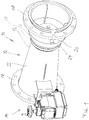
- Fig. 1 shows a Regulierschieber device, which is designated by the reference numeral 10.
- the Regulierschieber device 10 (hereafter called Regulierschieber) includes a flow channel component 12 and a fitting component 14, wherein the flow channel component 12 is inserted into a ventilation tube, which leads air, for example, in a clarifier of a sewage treatment plant.
- the valve component is mechanically connected to the flow channel component and serves to be able to adjust an element to be explained in the flow channel component.
- the flow channel component 12 has a housing 16 which carries at its two longitudinal ends in each case a flange 18, so that the flow channel component 12 can be easily installed in a pipeline.
- the housing 16 is divided into a plurality of housing longitudinal sections, namely an inlet longitudinal section 20, and an outlet longitudinal section 22. Between these two longitudinal sections, a further longitudinal section 24 is provided, in whose area an adjustment of the amount of air takes place, the flow channel component of the Inlet side flows through to the outlet side.
- these three housing longitudinal sections are provided as separate housing parts.
- the outlet longitudinal portion is cylindrical, wherein the diameter increases in the flow direction, so that a conical shape is formed.
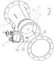
- Fig. 2 This conical shape of the outlet longitudinal section 22 can be seen even more clearly.
- the inlet longitudinal section 20, like the outlet longitudinal section 22, is of rotationally symmetrical design and has a section 26 tapering in the direction of the longitudinal section 24.
- the third longitudinal portion 24 serves as a seat ring 28 having an outer contour 31 which cooperates with the tapered portion 26 of the inlet longitudinal portion.
- the front end of the portion 26 is placed on the longitudinal portion 24, so that this end of the portion 26 sealingly abuts the outer contour 31.
- the seat ring 28 has, as in Fig. 2 can be seen, a further annular surface 30, which serves as a seat for a control element, which in Fig. 2 generally designated by the reference numeral 40.
- the control element 40 is preferably constructed rotationally symmetrical to the longitudinal axis and is divided into a plurality of sections, namely a valve portion 42 and an approximately hemispherical portion 44.
- the valve portion 42 has seen in the longitudinal direction an outer contour with a gradually or continuously varying diameter, wherein the diameter in the direction reduce the seat ring 28.
- the largest diameter is in a region adjacent to the hemispherical portion 44 and is adapted to the diameter of the annular surface 30 of the seat ring 28.
- the annular surface 30 is designed, so to speak, as a valve seat for the valve section 42.
- the control element 40 can be displaced in the longitudinal direction, such that the valve section 42 moves relative to the seat ring 28 and thus the annular surface 30.
- a displacement takes place against the flow direction to the right, so that the valve portion 42 moves from its seat on the annular surface 30 and opens an annular gap.
- the annular gap is thus formed between the annular surface 30 of the seat ring 28 and the opposite region of the valve section 42.
- this annular gap ie the area of the flow-through cross-section, increases with the displacement of the control element 40 to the right, since the diameter the valve portion 42 are smaller and thus the distance to the opposite annular surface 30 is greater.
- the change in the flow-through cross-sectional area of the annular gap is preferably linear with respect to the adjustment path, i. the adjustment of the control element in the longitudinal direction.
- This linearity can be achieved by appropriate choice of the different diameter of the valve portion 42.
- the diameters are chosen so that the volume flow through the annular gap, taking into account the dynamic system pressure loss behaves almost linearly to the adjustment of the control element along the adjustment.
- the different diameters can be calculated.
- the outer contour of the valve portion 42 is adjustable, so that the different diameters can be adjusted.
- Fig. 2 shows that several, preferably three baffles or flow baffles 52 are provided within the inlet longitudinal section 20. These baffles 52 are attached to the inside of the inlet longitudinal section 20 and preferably extend radially inwardly. The distribution of the plurality of baffles 52 is uniform in the circumferential direction.
- baffles 53 are provided within the housing 16, in particular within the outlet longitudinal section 22 , which extend from the inside of the outlet longitudinal section 22 radially inwardly.
- Fig. 2 are in the housing 16, ie in the outlet longitudinal section 22 slots 55 introduced, in which the baffles 53 can engage.
- the respective radially inner side of a baffle 53 is with an inner shaft housing connected later with respect to the Fig. 5 will be explained. This baffles also ensure a fixation and rotation of the shaft housing relative to the housing 16th
- Fig. 3 shows the inlet longitudinal section 20 again from a slightly different perspective. Good to see the baffles 52, which protrude radially inwardly and also extend in the longitudinal direction to the control element 40.
- a sensor 85 In the inlet longitudinal section and a sensor 85, in particular a sensor 85 is provided which protrudes through an opening in the inlet longitudinal section in the inner space.
- the Fig. 4 shows the Regulierschieber 10 as a sectional view, wherein the cutting plane is parallel to the longitudinal axis.
- control element 40 is hollow and receives various elements in the cavity.
- this cavity of the control element 40 projects, for example, one end of an output shaft 58 which extends centrally to the two longitudinal sections 20 and 22 and the other end terminates in a transmission housing 62.
- a threaded spindle 66 is preferably provided, which is designed to implement a rotational movement of the output shaft 58 in a translational movement of the control element 40 in the longitudinal direction.
- the output shaft 58 has for this purpose a threaded portion which cooperates with a spindle nut 68, wherein the spindle nut 68 is fixedly coupled to the control element 40.
- the spindle nut 68 displaces correspondingly in the longitudinal direction.
- the spindle nut is preferably provided with a clearance adjustment, which preferably has a spring.
- the drive of the output shaft 58 takes place within the transmission housing 62 via a deflection device 70, which couples an obliquely or perpendicular to the longitudinal direction of the drive shaft 72 to the output shaft 58.
- the deflection device is a bevel gear 74.
- the drive shaft 72 extends into the fitting component 14 and is there connected to a mechanical or motorized actuator to displace the control element 40 in the longitudinal direction can.
- control element 40, the shaft housing 78 and the gear housing 62 form a unit, which is preferably arranged centrally within the inlet longitudinal section and the outlet longitudinal section and thus within the flow channel. For this reason, this unit is designed as possible flow-optimized so that it exerts a positive influence on the flow behavior of the air flowing through the flow channel component 12.
- the shaft housing 78 and the gear housing 62 strömungsbemarkedd, so that the air flowing through the annular gap then flows as low friction along the inner wall of the outlet longitudinal portion 22, wherein the conical shape of the outlet longitudinal portion 22 in the flow direction additionally ensures that Reduction of the flow rate again pressure can be built up.
- the unit of gear housing 62, shaft housing 78 and control element 40 is preferably centered within the flow channel, which is formed by the inlet longitudinal portion and the outlet longitudinal portion, by a support member 80, the unit in the region of the gear housing 62 at the outlet longitudinal portion 22nd supported.
- the support element 80 preferably extends radially inward and has a flow-optimized design, so that its flow resistance is as low as possible.
- the support element 80 can be used by its shape flow calming and directionally.
- sensors are provided inside the flow channel component 12.
- Fig. 2 Such a sensor is shown schematically and designated by the reference numeral 85.
- This sensor 85 is provided in the inlet longitudinal section, wherein the position in the circumferential direction can be arbitrary. This is because the flow conditions within the inlet longitudinal section and thus also the pressure conditions are very homogeneous. This is because the air in the circumferential direction flows uniformly through the annular gap and the hemispherical shape of the portion 44 of the control element 40 for stable flow conditions by the accumulation effect ensures a uniform homogeneous pressure distribution. Further measuring sensors may be provided within the flow channel component, for example in the outlet longitudinal section 22.
- Fig. 5 is the drive group, which includes, among other things, the control element 40, the output shaft 58, the gear housing 62 and the shaft housing 78, again shown more clearly.
- the shaft housing 78 comprises two mutually displaceably held housing parts 78.1 and 78.2, wherein the housing part 78.1 with the gear housing 62 and the other housing part 78.2 with the control element 40, in particular the portion 44, is connected.
- the inner diameter of the housing part 78.2 is greater than the outer diameter of the housing part 78.1. This dimensioning allows the sliding of the housing part 78.2 on the housing part 78.1.
- the housing part 78.2 can move in the longitudinal direction relative to the other housing part 78.1, in particular move it.
- sliding strips can be provided on one and / or both housing parts.
- baffles are provided which are mounted on the housing part 78.1 and cooperate with correspondingly provided slots 56 in the housing part 78.2. These slots 56 extend in the longitudinal direction and are designed to open towards the gear housing 62.
- the housing part 78.2 When the control element 40 is adjusted in the longitudinal direction, the housing part 78.2 also moves relative to the housing part 78.1 and provides the necessary guidance and torsional safety.
- the described Regulierschieber device is particularly well suited for use in ventilation systems for sewage treatment plants.
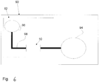
- Fig. 6 schematically shows a treatment plant 90 with a ventilation system 92, which includes at least one compressor system 96 and piping 98, and a clarifier 94 shown.
- the Regulierschieber device 10 can be used in existing pipelines 98 with relatively little effort for the previous facilities, so that said energy savings can be achieved for existing treatment plants. Due to the low pressure losses, the compressor system 96, which introduces air into pipes 98, can be operated with lower output pressure and consequently lower electrical power.
Landscapes
- Engineering & Computer Science (AREA)
- General Engineering & Computer Science (AREA)
- Mechanical Engineering (AREA)
- Chemical & Material Sciences (AREA)
- Physics & Mathematics (AREA)
- Fluid Mechanics (AREA)
- Chemical Kinetics & Catalysis (AREA)
- Life Sciences & Earth Sciences (AREA)
- Hydrology & Water Resources (AREA)
- Environmental & Geological Engineering (AREA)
- Water Supply & Treatment (AREA)
- Organic Chemistry (AREA)
- Flow Control (AREA)
- Lift Valve (AREA)
- Sliding Valves (AREA)
Priority Applications (1)
| Application Number | Priority Date | Filing Date | Title |
|---|---|---|---|
| PL13770664T PL2898246T3 (pl) | 2012-09-24 | 2013-09-24 | Trójwymiarowy, zoptymalizowany pod względem przepływu układ zasuwy regulacyjnej o liniowej charakterystyce regulacji |
Applications Claiming Priority (2)
| Application Number | Priority Date | Filing Date | Title |
|---|---|---|---|
| DE102012018763 | 2012-09-24 | ||
| PCT/EP2013/069773 WO2014044861A1 (de) | 2012-09-24 | 2013-09-24 | Dreidimensionales strömungsoptimiertes regelschiebersystem mit linearem regelverhalten |
Publications (2)
| Publication Number | Publication Date |
|---|---|
| EP2898246A1 EP2898246A1 (de) | 2015-07-29 |
| EP2898246B1 true EP2898246B1 (de) | 2019-05-22 |
Family
ID=49263302
Family Applications (1)
| Application Number | Title | Priority Date | Filing Date |
|---|---|---|---|
| EP13770664.4A Active EP2898246B1 (de) | 2012-09-24 | 2013-09-24 | Dreidimensionales strömungsoptimiertes regelschiebersystem mit linearem regelverhalten |
Country Status (8)
| Country | Link |
|---|---|
| US (1) | US9644751B2 (pl) |
| EP (1) | EP2898246B1 (pl) |
| JP (1) | JP6096302B2 (pl) |
| CN (1) | CN104769345B (pl) |
| DE (1) | DE102013110518B4 (pl) |
| ES (1) | ES2739851T3 (pl) |
| PL (1) | PL2898246T3 (pl) |
| WO (1) | WO2014044861A1 (pl) |
Families Citing this family (6)
| Publication number | Priority date | Publication date | Assignee | Title |
|---|---|---|---|---|
| CN106499867A (zh) * | 2015-09-08 | 2017-03-15 | 赵学锋 | 一种开关阀门扳手 |
| DE102021107198A1 (de) | 2021-03-23 | 2022-09-29 | Binder Gmbh | Regelventil zur Regelung eines Gasdurchflusses |
| CN113251149A (zh) * | 2021-06-17 | 2021-08-13 | 江苏润田水工业设备有限公司 | 智能无极空气调节阀 |
| CN114950202B (zh) * | 2022-07-13 | 2024-10-25 | 淮安市飞隆环保设备有限公司 | 一种水处理系统中的加药装置 |
| CN116592142A (zh) * | 2023-05-16 | 2023-08-15 | 徐州市市政设计院有限公司 | 流量阀 |
| CN116464787A (zh) * | 2023-05-16 | 2023-07-21 | 徐州市市政设计院有限公司 | 文丘里阀 |
Family Cites Families (18)
| Publication number | Priority date | Publication date | Assignee | Title |
|---|---|---|---|---|
| US3317184A (en) * | 1967-05-02 | Pintle valve and flow collimator | ||
| FR1309839A (fr) * | 1961-06-13 | 1962-11-23 | Bertin & Cie | Vanne équilibrée, notamment pour gaz chauds |
| US3520324A (en) * | 1965-10-12 | 1970-07-14 | Santina Meregalli | Valve operating simultaneously as intercepting,register and check valve for fluid flows |
| JPS5977179A (ja) * | 1982-10-27 | 1984-05-02 | Syst Hoomuzu:Kk | 電子膨張弁 |
| JPS6435185A (en) * | 1987-07-30 | 1989-02-06 | Fuji Photo Film Co Ltd | Flow control valve |
| JPH0773203B2 (ja) | 1987-11-04 | 1995-08-02 | 三菱電機株式会社 | ゲートターンオフサイリスタのゲート回路 |
| JPH0360604U (pl) * | 1989-10-18 | 1991-06-14 | ||
| JPH07301345A (ja) * | 1994-04-30 | 1995-11-14 | Horiba Ltd | 可変型臨界流ベンチュリ |
| US5782410A (en) * | 1994-10-31 | 1998-07-21 | Weston; Colin K. | Fluid flow control device |
| JPH11325264A (ja) * | 1998-05-19 | 1999-11-26 | Toshimitsu Araki | 可変流量制御弁 |
| GB9924524D0 (en) * | 1999-10-15 | 1999-12-15 | Bawden Nigel A | Landfill gas control valve |
| US7137612B2 (en) * | 2003-09-04 | 2006-11-21 | Whittaker Corporation | High recovery metering valve |
| JP4798987B2 (ja) * | 2004-11-25 | 2011-10-19 | サーパス工業株式会社 | 流量調節弁 |
| JP2006292137A (ja) * | 2005-04-14 | 2006-10-26 | Ckd Corp | 流量制御弁 |
| JP2007198893A (ja) * | 2006-01-26 | 2007-08-09 | Toyota Motor Corp | ガスセンサ |
| DE102008026206A1 (de) * | 2008-05-30 | 2009-12-03 | Invent Umwelt- Und Verfahrenstechnik Ag | Vorrichtung zum Reinigen von Abwasser |
| DE102010005101B4 (de) * | 2010-01-20 | 2011-09-01 | Poppe & Potthoff Gmbh | Druckbegrenzungsventil, insbesondere zum Begrenzen des Fluiddruckes in einem Verteilerrohr eines Common-Rail-Einspritzsystems |
| EP2463558A1 (en) * | 2010-12-07 | 2012-06-13 | TA Hydronics S.A. | Improvements in balancing and control valves |
-
2013
- 2013-09-24 CN CN201380049694.1A patent/CN104769345B/zh active Active
- 2013-09-24 EP EP13770664.4A patent/EP2898246B1/de active Active
- 2013-09-24 DE DE102013110518.1A patent/DE102013110518B4/de not_active Expired - Fee Related
- 2013-09-24 WO PCT/EP2013/069773 patent/WO2014044861A1/de not_active Ceased
- 2013-09-24 PL PL13770664T patent/PL2898246T3/pl unknown
- 2013-09-24 ES ES13770664T patent/ES2739851T3/es active Active
- 2013-09-24 JP JP2015532446A patent/JP6096302B2/ja active Active
-
2015
- 2015-03-23 US US14/665,458 patent/US9644751B2/en active Active
Non-Patent Citations (1)
| Title |
|---|
| None * |
Also Published As
| Publication number | Publication date |
|---|---|
| US20150240953A1 (en) | 2015-08-27 |
| WO2014044861A1 (de) | 2014-03-27 |
| US9644751B2 (en) | 2017-05-09 |
| CN104769345A (zh) | 2015-07-08 |
| PL2898246T3 (pl) | 2019-10-31 |
| DE102013110518B4 (de) | 2016-07-28 |
| JP6096302B2 (ja) | 2017-03-15 |
| JP2015532967A (ja) | 2015-11-16 |
| EP2898246A1 (de) | 2015-07-29 |
| ES2739851T3 (es) | 2020-02-04 |
| CN104769345B (zh) | 2018-06-22 |
| DE102013110518A1 (de) | 2014-03-27 |
Similar Documents
| Publication | Publication Date | Title |
|---|---|---|
| EP2898246B1 (de) | Dreidimensionales strömungsoptimiertes regelschiebersystem mit linearem regelverhalten | |
| EP3104246B1 (de) | Durchflussregelventil | |
| EP2226697B1 (de) | Durchflussmengenregler | |
| DE102014110550B4 (de) | Regelarmatur | |
| EP0310595B1 (de) | Regelventil | |
| EP2988071B1 (de) | Durchflussmengenregler | |
| WO2004003673A1 (de) | Durchflussmengenregler | |
| DE102007008285B4 (de) | Strömungswächter und entsprechende Verbindungsanordnung | |
| EP1859329B1 (de) | Durchflussmengenregler | |
| EP3997367B1 (de) | Armaturanordnung | |
| DE102020003753A1 (de) | Ventil | |
| EP4039894B1 (de) | Vorrichtung zur entkeimung von trinkwasser | |
| EP0753692A1 (de) | Regelsystem zur Regelung von Durchflussmindestmengen und Rückschlagventil | |
| DE102005011947B3 (de) | Durchflussmengenregler | |
| DE112022003184T5 (de) | Schrank für kaltes und warmes verbrauchswasser mit den erforderlichen ventilen und verteilungsrohren | |
| DE557281C (de) | Regelbarer Stossdaempfer | |
| EP0281126B1 (de) | Vorrichtung zum Messen oder Dosieren von strömenden Medien | |
| EP4314602B1 (de) | Regelventil zur regelung eines gasdurchflusses | |
| DE3146921C2 (de) | Regelarmatur zur variablen Drosselung eines Flüssigkeitsstromes | |
| DE102014004907A1 (de) | Durchflussregelventil | |
| DE2740761C3 (de) | Dampfleitung | |
| DE3632690C2 (pl) | ||
| WO2016000987A1 (de) | Ringkolbenventil | |
| AT517766B1 (de) | Kühlmittelpumpe | |
| WO2003014691A1 (de) | Drucktransmitterinstallation an einer prozessleitung einer prozessanlage |
Legal Events
| Date | Code | Title | Description |
|---|---|---|---|
| PUAI | Public reference made under article 153(3) epc to a published international application that has entered the european phase |
Free format text: ORIGINAL CODE: 0009012 |
|
| 17P | Request for examination filed |
Effective date: 20150319 |
|
| AK | Designated contracting states |
Kind code of ref document: A1 Designated state(s): AL AT BE BG CH CY CZ DE DK EE ES FI FR GB GR HR HU IE IS IT LI LT LU LV MC MK MT NL NO PL PT RO RS SE SI SK SM TR |
|
| AX | Request for extension of the european patent |
Extension state: BA ME |
|
| DAX | Request for extension of the european patent (deleted) | ||
| STAA | Information on the status of an ep patent application or granted ep patent |
Free format text: STATUS: EXAMINATION IS IN PROGRESS |
|
| 17Q | First examination report despatched |
Effective date: 20171109 |
|
| GRAP | Despatch of communication of intention to grant a patent |
Free format text: ORIGINAL CODE: EPIDOSNIGR1 |
|
| STAA | Information on the status of an ep patent application or granted ep patent |
Free format text: STATUS: GRANT OF PATENT IS INTENDED |
|
| INTG | Intention to grant announced |
Effective date: 20181205 |
|
| GRAS | Grant fee paid |
Free format text: ORIGINAL CODE: EPIDOSNIGR3 |
|
| GRAA | (expected) grant |
Free format text: ORIGINAL CODE: 0009210 |
|
| STAA | Information on the status of an ep patent application or granted ep patent |
Free format text: STATUS: THE PATENT HAS BEEN GRANTED |
|
| AK | Designated contracting states |
Kind code of ref document: B1 Designated state(s): AL AT BE BG CH CY CZ DE DK EE ES FI FR GB GR HR HU IE IS IT LI LT LU LV MC MK MT NL NO PL PT RO RS SE SI SK SM TR |
|
| REG | Reference to a national code |
Ref country code: GB Ref legal event code: FG4D Free format text: NOT ENGLISH |
|
| REG | Reference to a national code |
Ref country code: CH Ref legal event code: EP |
|
| REG | Reference to a national code |
Ref country code: IE Ref legal event code: FG4D Free format text: LANGUAGE OF EP DOCUMENT: GERMAN |
|
| REG | Reference to a national code |
Ref country code: AT Ref legal event code: REF Ref document number: 1136525 Country of ref document: AT Kind code of ref document: T Effective date: 20190615 |
|
| REG | Reference to a national code |
Ref country code: DE Ref legal event code: R096 Ref document number: 502013012884 Country of ref document: DE |
|
| REG | Reference to a national code |
Ref country code: NL Ref legal event code: FP |
|
| REG | Reference to a national code |
Ref country code: LT Ref legal event code: MG4D |
|
| PG25 | Lapsed in a contracting state [announced via postgrant information from national office to epo] |
Ref country code: HR Free format text: LAPSE BECAUSE OF FAILURE TO SUBMIT A TRANSLATION OF THE DESCRIPTION OR TO PAY THE FEE WITHIN THE PRESCRIBED TIME-LIMIT Effective date: 20190522 Ref country code: LT Free format text: LAPSE BECAUSE OF FAILURE TO SUBMIT A TRANSLATION OF THE DESCRIPTION OR TO PAY THE FEE WITHIN THE PRESCRIBED TIME-LIMIT Effective date: 20190522 Ref country code: SE Free format text: LAPSE BECAUSE OF FAILURE TO SUBMIT A TRANSLATION OF THE DESCRIPTION OR TO PAY THE FEE WITHIN THE PRESCRIBED TIME-LIMIT Effective date: 20190522 Ref country code: NO Free format text: LAPSE BECAUSE OF FAILURE TO SUBMIT A TRANSLATION OF THE DESCRIPTION OR TO PAY THE FEE WITHIN THE PRESCRIBED TIME-LIMIT Effective date: 20190822 Ref country code: PT Free format text: LAPSE BECAUSE OF FAILURE TO SUBMIT A TRANSLATION OF THE DESCRIPTION OR TO PAY THE FEE WITHIN THE PRESCRIBED TIME-LIMIT Effective date: 20190922 Ref country code: AL Free format text: LAPSE BECAUSE OF FAILURE TO SUBMIT A TRANSLATION OF THE DESCRIPTION OR TO PAY THE FEE WITHIN THE PRESCRIBED TIME-LIMIT Effective date: 20190522 Ref country code: FI Free format text: LAPSE BECAUSE OF FAILURE TO SUBMIT A TRANSLATION OF THE DESCRIPTION OR TO PAY THE FEE WITHIN THE PRESCRIBED TIME-LIMIT Effective date: 20190522 |
|
| PG25 | Lapsed in a contracting state [announced via postgrant information from national office to epo] |
Ref country code: BG Free format text: LAPSE BECAUSE OF FAILURE TO SUBMIT A TRANSLATION OF THE DESCRIPTION OR TO PAY THE FEE WITHIN THE PRESCRIBED TIME-LIMIT Effective date: 20190822 Ref country code: GR Free format text: LAPSE BECAUSE OF FAILURE TO SUBMIT A TRANSLATION OF THE DESCRIPTION OR TO PAY THE FEE WITHIN THE PRESCRIBED TIME-LIMIT Effective date: 20190823 Ref country code: RS Free format text: LAPSE BECAUSE OF FAILURE TO SUBMIT A TRANSLATION OF THE DESCRIPTION OR TO PAY THE FEE WITHIN THE PRESCRIBED TIME-LIMIT Effective date: 20190522 Ref country code: LV Free format text: LAPSE BECAUSE OF FAILURE TO SUBMIT A TRANSLATION OF THE DESCRIPTION OR TO PAY THE FEE WITHIN THE PRESCRIBED TIME-LIMIT Effective date: 20190522 |
|
| PG25 | Lapsed in a contracting state [announced via postgrant information from national office to epo] |
Ref country code: EE Free format text: LAPSE BECAUSE OF FAILURE TO SUBMIT A TRANSLATION OF THE DESCRIPTION OR TO PAY THE FEE WITHIN THE PRESCRIBED TIME-LIMIT Effective date: 20190522 Ref country code: DK Free format text: LAPSE BECAUSE OF FAILURE TO SUBMIT A TRANSLATION OF THE DESCRIPTION OR TO PAY THE FEE WITHIN THE PRESCRIBED TIME-LIMIT Effective date: 20190522 Ref country code: SK Free format text: LAPSE BECAUSE OF FAILURE TO SUBMIT A TRANSLATION OF THE DESCRIPTION OR TO PAY THE FEE WITHIN THE PRESCRIBED TIME-LIMIT Effective date: 20190522 Ref country code: CZ Free format text: LAPSE BECAUSE OF FAILURE TO SUBMIT A TRANSLATION OF THE DESCRIPTION OR TO PAY THE FEE WITHIN THE PRESCRIBED TIME-LIMIT Effective date: 20190522 Ref country code: RO Free format text: LAPSE BECAUSE OF FAILURE TO SUBMIT A TRANSLATION OF THE DESCRIPTION OR TO PAY THE FEE WITHIN THE PRESCRIBED TIME-LIMIT Effective date: 20190522 |
|
| REG | Reference to a national code |
Ref country code: ES Ref legal event code: FG2A Ref document number: 2739851 Country of ref document: ES Kind code of ref document: T3 Effective date: 20200204 |
|
| REG | Reference to a national code |
Ref country code: DE Ref legal event code: R097 Ref document number: 502013012884 Country of ref document: DE |
|
| PG25 | Lapsed in a contracting state [announced via postgrant information from national office to epo] |
Ref country code: SM Free format text: LAPSE BECAUSE OF FAILURE TO SUBMIT A TRANSLATION OF THE DESCRIPTION OR TO PAY THE FEE WITHIN THE PRESCRIBED TIME-LIMIT Effective date: 20190522 |
|
| PLBE | No opposition filed within time limit |
Free format text: ORIGINAL CODE: 0009261 |
|
| STAA | Information on the status of an ep patent application or granted ep patent |
Free format text: STATUS: NO OPPOSITION FILED WITHIN TIME LIMIT |
|
| 26N | No opposition filed |
Effective date: 20200225 |
|
| PG25 | Lapsed in a contracting state [announced via postgrant information from national office to epo] |
Ref country code: SI Free format text: LAPSE BECAUSE OF FAILURE TO SUBMIT A TRANSLATION OF THE DESCRIPTION OR TO PAY THE FEE WITHIN THE PRESCRIBED TIME-LIMIT Effective date: 20190522 Ref country code: MC Free format text: LAPSE BECAUSE OF FAILURE TO SUBMIT A TRANSLATION OF THE DESCRIPTION OR TO PAY THE FEE WITHIN THE PRESCRIBED TIME-LIMIT Effective date: 20190522 |
|
| PG25 | Lapsed in a contracting state [announced via postgrant information from national office to epo] |
Ref country code: IE Free format text: LAPSE BECAUSE OF NON-PAYMENT OF DUE FEES Effective date: 20190924 Ref country code: LU Free format text: LAPSE BECAUSE OF NON-PAYMENT OF DUE FEES Effective date: 20190924 |
|
| PG25 | Lapsed in a contracting state [announced via postgrant information from national office to epo] |
Ref country code: CY Free format text: LAPSE BECAUSE OF FAILURE TO SUBMIT A TRANSLATION OF THE DESCRIPTION OR TO PAY THE FEE WITHIN THE PRESCRIBED TIME-LIMIT Effective date: 20190522 |
|
| PG25 | Lapsed in a contracting state [announced via postgrant information from national office to epo] |
Ref country code: IS Free format text: LAPSE BECAUSE OF FAILURE TO SUBMIT A TRANSLATION OF THE DESCRIPTION OR TO PAY THE FEE WITHIN THE PRESCRIBED TIME-LIMIT Effective date: 20190922 |
|
| PG25 | Lapsed in a contracting state [announced via postgrant information from national office to epo] |
Ref country code: HU Free format text: LAPSE BECAUSE OF FAILURE TO SUBMIT A TRANSLATION OF THE DESCRIPTION OR TO PAY THE FEE WITHIN THE PRESCRIBED TIME-LIMIT; INVALID AB INITIO Effective date: 20130924 Ref country code: MT Free format text: LAPSE BECAUSE OF FAILURE TO SUBMIT A TRANSLATION OF THE DESCRIPTION OR TO PAY THE FEE WITHIN THE PRESCRIBED TIME-LIMIT Effective date: 20190522 |
|
| PG25 | Lapsed in a contracting state [announced via postgrant information from national office to epo] |
Ref country code: MK Free format text: LAPSE BECAUSE OF FAILURE TO SUBMIT A TRANSLATION OF THE DESCRIPTION OR TO PAY THE FEE WITHIN THE PRESCRIBED TIME-LIMIT Effective date: 20190522 |
|
| REG | Reference to a national code |
Ref country code: CH Ref legal event code: U11 Free format text: ST27 STATUS EVENT CODE: U-0-0-U10-U11 (AS PROVIDED BY THE NATIONAL OFFICE) Effective date: 20251001 |
|
| PGFP | Annual fee paid to national office [announced via postgrant information from national office to epo] |
Ref country code: DE Payment date: 20250924 Year of fee payment: 13 |
|
| PGFP | Annual fee paid to national office [announced via postgrant information from national office to epo] |
Ref country code: PL Payment date: 20250822 Year of fee payment: 13 Ref country code: TR Payment date: 20250916 Year of fee payment: 13 Ref country code: IT Payment date: 20250923 Year of fee payment: 13 Ref country code: NL Payment date: 20250918 Year of fee payment: 13 |
|
| PGFP | Annual fee paid to national office [announced via postgrant information from national office to epo] |
Ref country code: BE Payment date: 20250918 Year of fee payment: 13 Ref country code: GB Payment date: 20250918 Year of fee payment: 13 |
|
| PGFP | Annual fee paid to national office [announced via postgrant information from national office to epo] |
Ref country code: AT Payment date: 20250919 Year of fee payment: 13 Ref country code: FR Payment date: 20250922 Year of fee payment: 13 |
|
| PGFP | Annual fee paid to national office [announced via postgrant information from national office to epo] |
Ref country code: CH Payment date: 20251001 Year of fee payment: 13 |
|
| PGFP | Annual fee paid to national office [announced via postgrant information from national office to epo] |
Ref country code: ES Payment date: 20251028 Year of fee payment: 13 |