EP2898793B1 - Ensemble coulissant - Google Patents
Ensemble coulissant Download PDFInfo
- Publication number
- EP2898793B1 EP2898793B1 EP14152234.2A EP14152234A EP2898793B1 EP 2898793 B1 EP2898793 B1 EP 2898793B1 EP 14152234 A EP14152234 A EP 14152234A EP 2898793 B1 EP2898793 B1 EP 2898793B1
- Authority
- EP
- European Patent Office
- Prior art keywords
- rail
- elongate body
- slide assembly
- resilient arm
- opening
- Prior art date
- Legal status (The legal status is an assumption and is not a legal conclusion. Google has not performed a legal analysis and makes no representation as to the accuracy of the status listed.)
- Active
Links
Images






Classifications
-
- A—HUMAN NECESSITIES
- A47—FURNITURE; DOMESTIC ARTICLES OR APPLIANCES; COFFEE MILLS; SPICE MILLS; SUCTION CLEANERS IN GENERAL
- A47B—TABLES; DESKS; OFFICE FURNITURE; CABINETS; DRAWERS; GENERAL DETAILS OF FURNITURE
- A47B88/00—Drawers for tables, cabinets or like furniture; Guides for drawers
- A47B88/40—Sliding drawers; Slides or guides therefor
- A47B88/423—Fastening devices for slides or guides
- A47B88/43—Fastening devices for slides or guides at cabinet side
-
- A—HUMAN NECESSITIES
- A47—FURNITURE; DOMESTIC ARTICLES OR APPLIANCES; COFFEE MILLS; SPICE MILLS; SUCTION CLEANERS IN GENERAL
- A47B—TABLES; DESKS; OFFICE FURNITURE; CABINETS; DRAWERS; GENERAL DETAILS OF FURNITURE
- A47B88/00—Drawers for tables, cabinets or like furniture; Guides for drawers
- A47B88/40—Sliding drawers; Slides or guides therefor
- A47B88/423—Fastening devices for slides or guides
-
- A—HUMAN NECESSITIES
- A47—FURNITURE; DOMESTIC ARTICLES OR APPLIANCES; COFFEE MILLS; SPICE MILLS; SUCTION CLEANERS IN GENERAL
- A47B—TABLES; DESKS; OFFICE FURNITURE; CABINETS; DRAWERS; GENERAL DETAILS OF FURNITURE
- A47B88/00—Drawers for tables, cabinets or like furniture; Guides for drawers
- A47B88/40—Sliding drawers; Slides or guides therefor
- A47B88/423—Fastening devices for slides or guides
- A47B88/427—Fastening devices for slides or guides at drawer side
Definitions
- the present invention relates to a slide assembly, and more particularly, to a slide assembly capable of quickly installed between a cabinet and a drawer.
- U.S. Patent No. 5,457,867 to Maberry et al. discloses a slide assembly and is incorporated herein by reference, which uses rollers 24, 40 as sliding media and comprises a cabinet member 14 and a drawer member 38 slidably connected to the cabinet member 14.
- the cabinet member 14 is fixed to a cabinet panel 12 by a pair of bushings 16, 18 and a pair of screws 20A, 20B, and the drawer member 38 is fixed to a side of a drawer 36 such that the drawer 36 is slidably connected to the cabinet member 14 by the drawer member 38 and easily slides relative to the cabinet panel 12.
- the slide assembly using the rollers 24, 40 mentioned above allows a larger assembly tolerance between the drawer 36 and the cabinet panel 12, so that, for the furniture manufacturers, the precision for the drawer 36 and the cabinet panel 12 can be compromised and needs not to be compared with industrial precision. Therefore, the slide assemblies using rollers 24, 40 are widely used on furniture combinations. Nevertheless, the slide assemblies using the rollers have restriction of the loads. Furthermore, as to compensate the assembly tolerance, the slide assemblies are not easily to be combined with soft-closing or push-open design to increase their values.
- U.S. Patent No. 5,895,101 to Cabrales et al. discloses a slide assembly and is incorporated herein by reference, which uses ball bearings as sliding media, and the ball bearings have higher standard of precision and can bear relative high load, so that they are welcomed by customers. Furthermore, the ball bearings can be combined with soft-closing design, such as the disclosure of U.S. Patent No. 6,712,435 B2 to Kim et al. However, the high precision of the ball bearings makes them to be squeezed by the drawer and the cabinet when the assembly tolerance between the drawer and the cabinet is beyond the permissible range of the slide assembly. This will result awkward operation of the drawers.
- U.S. Publication No. 2013/0106271 A1 to Anderson et al. discloses a rail assembly having at least one fixed member 56 and at least one floating member 54 and is incorporated herein by reference.
- the at least one fixed member 56 is transversely connected to a drawer slide
- the at least one floating member 54 is transversely and slidably connected to the fixed member 56. This arrangement permits a relatively large assembly tolerance between the drawer and the cabinet.
- the floating member 54 has a quality flaw such as the floating member is broken or the assembly tolerance between the drawer and the cabinet is too large, the floating member 54 might drop from the fixed member 56, and thus, the position to which the whole set of the rail assembly is installed does not permit to have the relative large tolerance between the drawer and the cabinet.
- the present invention intends to provide a slide assembly that has a support member which is able to move a limited distance so as to compensate the displacement because of installation tolerance.
- the present invention relates to a slide assembly.
- the slide assembly comprises a first rail having a first elongate body.
- a second rail is longitudinally slidable relative to the first rail and has a second elongate body, wherein at least one of the first elongate body and the second elongate body has an opening.
- the slide assembly comprises further at least one positioning device and a fixing member.
- At least one positioning device has a support member and a dowel.
- the support member has a fixing portion and a resilient arm connected to the fixing portion.
- the fixing portion is fixed to the at least one of the first elongate body and the second elongate body.
- the at least one portion of the resilient arm is fitted within the opening and supported by an inner wall of the opening.
- the dowel is disposed on the at least one portion of the resilient arm.
- the fixing member is transversely extending through the resilient arm of the support member and being fixed to the dowel.
- At least one portion of the resilient arm is fitted within the opening, and the resilient arm has a bent portion abutting against an inner wall of the opening.
- a ball bearing retainer is disposed between the first rail and the second rail.
- the ball bearing retainer retains a plurality of ball bearings therewith so as to facilitate sliding movement of the second rail relative to the first rail.
- an intermediate rail is slidably connected between the first rail and the second rail.
- a first ball bearing retainer is disposed between the first rail and the intermediate rail and retains a plurality of first ball bearings therewith so as to facilitate sliding movement of the intermediate rail relative to the first rail.
- a second ball bearing retainer is disposed between the second rail and the intermediate rail and retains a plurality of second ball bearings therewith so as to facilitate sliding movement of the second rail relative to the intermediate rail.
- the slide assembly further comprises a connection frame having a slot and at least one latch, wherein a distal end of the first rail is inserted into the slot of the connection frame.
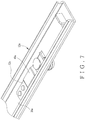
- a slide assembly in accordance with a preferred embodiment of the present invention comprises a first rail 10, a second rail 12 and at least one positioning device 14.
- the first rail 10 has a first elongate body 16, and the first elongate body 16 has a first wall 18, a second wall 20 opposite to the first wall 18, and a side wall 22 extending between the first wall 18 and the second wall 20, wherein a path 24 is bounded by the first wall 18, the second wall 20 and the side wall 22.
- the second rail 12 is slidably received in the path 24 of the first rail 10 such that the second rail 12 is longitudinally movable relative to the first rail 10.
- the second rail 12 has a second elongate body 26, wherein the second elongate body 26 has two lateral walls 28, 30 and an intermediate wall 32 extending between the two lateral walls 28, 30.
- the slide assembly further comprises a connection frame 36 which has a slot 38 and at least one latch 40, and a distal end 34 of the first rail 10 is inserted into the slot 38 of the connection frame 36 such that the slide assembly is adapted to be fixed to a cabinet (not shown) by the at least one latch 40 of the connection frame 36.
- a ball bearing retainer 42 is disposed between the first rail 10 and the second rail 12 and retains a plurality of ball bearings 42 therewith so as to facilitate sliding movement of the second rail 12 relative to the first rail 10, thus forming a two-stage ball bearing slide assembly.
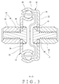
- the at least one positioning device 14 has a support member 48 and a dowel 50.
- the intermediate wall 32 of the second elongate body 26 of the second rail 12 has an opening 46 defined therein, and the at least one positioning device 14 is connected to the intermediate wall 32 of the second elongate body 26 of the second rail 12.
- the support member 48 of the at least one positioning device 14 has a fixing portion 52 and a resilient arm 54.
- the resilient arm 54 is connected to the fixing portion 52, and the fixing portion 52 is securely connected to the second elongate body 26 of the second rail 12.
- the fixing portion 52 can be fixed to the second elongate body 26 by way of threading, riveting, or any known method, but the fixing portion 52 also can be integrally formed with the second elongate body 26 by way of punching, stamping, or any known method.
- At least one portion of the resilient arm 54 is fitted within the opening 46 and is supported by an inner wall of the opening 46.
- the resilient arm 54 has a bent portion 56, and the bent portion 56 abuts against the inner wall of the opening 46 when the at least one portion of the resilient arm 54 fitted within the opening 46 is moved in response to a force applied thereon.
- the dowel 50 is disposed on the resilient arm 54 of the support member 48 and corresponds in position to the opening 46. In other words, the dowel 50 is disposed on the at least one portion of the resilient arm 54, such that the dowel 50 is allowed to be transversely moved together with the at least one portion of the resilient arm 54 relative to the slide assembly.
- the positioning device 14 has a fixing member 58 which transversely extends through the resilient arm 54 of the support member 48 and is securely fixed to the dowel 50.
- the fixing member 58 can be fixed to the dowel 50 by way of threading, riveting, or any known method.
- the opening 46 is defined in the side wall 22 of the first elongate body 16 of the first rail 10, and the at least one positioning device 14 is connected to the side wall 22 of the first elongate body 16 of the first rail 10, wherein the fixing portion 52 of the support member 48 of the at least one positioning device 14 is securely connected to the first elongate body 16 of the first rail 10.
- the remaining arrangement and operation of the at least one positioning device 14 on the first elongate body 16 of the first rail 10 are the same as those disclosed above; thus, an explanation thereof is eliminated herein.
- the opening 46 and the at least one positioning device 14 is disposed on the first elongate body 16 and/or the second elongate body 26.
- the opening 46 and the at least one positioning device 14 can be disposed on one of the first elongate body 16 and the second elongate body 26, or be disposed on both of the first elongate body 16 and the second elongate body 26.
- the first elongate body 16 of the first rail 10 and the second elongate body 26 of the second rail 12 each have the opening 46 and the positioning device 14 disposed thereon, and wherein the dowel 50 of the positioning device 14 disposed on the first elongate body 16 is installed to a cabinet 62, and the dowel 50 of the positioning device 14 disposed on the second elongate body 26 is installed to a drawer 60.
- the dowels 50 are disposed on their respective resilient arms 54, when there is an assembly tolerance between the drawer 60 and the cabinet 62, the dowels 50 are capable of being moved transversely together with their respective resilient arms 54 to compensate the tolerance "d” and therefore facilitate rolling movement of the ball bearings 44 retained by the ball bearing retainer 42.
- the dowel 50 and the fixing member 58 are secured together to form an integral member, which has better structural strength, so as to avoid the dowel 50 from deformation, broken and dropping from the support member 48 because of quality flaw or over-load.
- Fig. 7 shows a second embodiment of the present invention, wherein the support member 48a and the second elongate body 26a of the second rail 12a are two individual members and are connected to each other by fixing the fixing portion 52a of the support member 48a to the second elongate body 26a of the second rail 12a by way of riveting.
- FIGS. 8a and 8b show a third embodiment of the present invention wherein the whole resilient arm 54a is fitted within the opening 46a of the second rail 12b and corresponds in shape to the inner wall of the opening 46a. Therefore, when the resilient arm 54a is resiliently moved within the opening 46a, the contact between the inner wall of the opening 46a and the resilient arm 54a is of large area, and thus the resilient arm 54a is better supported by the inner wall of the opening 46a.
- FIG. 9 shows a fourth embodiment of the present invention, wherein an intermediate rail 64 is slidably connected between the first rail 100 and the second rail 120. Furthermore, a first ball bearing retainer 66 is disposed between the first rail 100 and the intermediate rail 64 and retains a plurality of first ball bearings 68 therewith so as to facilitate sliding movement of the intermediate rail 64 relative to the first rail 100, and a second ball bearing retainer 70 is disposed between the second rail 120 and the intermediate rail 64 and retains a plurality of second ball bearings 72 therewith so as to facilitate sliding movement of the second rail 120 relative to the intermediate rail 64, thus forming a three-stage slide assembly.
- FIG. 10 shows a fifth embodiment of the present invention, wherein the resilient arm 54b has an installation hole 74.
- the dowel 50a is tubular-shaped and has a plurality of axial slots 76 and an engaging portion 78 disposed thereon.
- the plurality of axial slots 76 enables the dowel 50a to be flexible, and thus the dowel 50a can be inserted into the installation hole 74 by the flexibility thereof and then be securely connected to the resilient arm 54b by the engaging portion 78 thereof.
Landscapes
- Drawers Of Furniture (AREA)
Claims (5)
- Un ensemble coulissant comprenant :un premier rail (10) présentant un premier corps allongé (16) ; etun second rail (12) étant longitudinalement coulissant par rapport au premier rail (10) et présentant un second corps allongé (26), dans lequel au moins l'un des premier corps allongé (16) et second corps allongé (26) présente une ouverture (46) ; caractérisé en ce que l'ensemble coulissant comprend en outre au moins un dispositif de positionnement (14) et un élément de fixation (58), le ou les dispositifs de positionnement (14) présentant un élément de support (48) et une cheville (50), dans lequel l'élément de support (48) présente une partie de fixation (52) et un bras élastique (54) raccordé à la partie de fixation (52), dans lequel la partie de fixation (52) est fixée sur au moins l'un des premier corps allongé (16) et second corps allongé (26), tandis qu'au moins une partie du bras élastique (54) est montée dans l'ouverture (46) et supportée par une paroi interne de l'ouverture (46), la cheville (50) est disposée sur au moins une partie du bras élastique (54), et l'élément de fixation (58) s'étendant transversalement au travers du bras élastique (54) de l'élément de support (48) et étant fixé sûrement à la cheville (50).
- L'ensemble coulissant selon la revendication 1, dans lequel au moins une partie du bras élastique (54) est montée dans l'ouverture (46), et le bras élastique (54) présente une partie courbée (56) en butée contre une paroi interne de l'ouverture (46).
- L'ensemble coulissant selon la revendication 1, comprenant en outre un élément de retenue de roulement à bille (42) disposé entre le premier rail (10) et le second rail (12), l'élément de retenue de roulements à bille (42) retenant une pluralité de roulements à bille (44) avec celui-ci de façon à faciliter le mouvement coulissant du second rail (12) par rapport au premier rail (10).
- L'ensemble coulissant selon la revendication 1, comprenant en outre un rail intermédiaire (64), un premier élément de retenue de roulement à bille (66) et un second élément de retenue de roulement à bille (70), dans lequel le rail intermédiaire (64) est raccordé de façon coulissante entre le premier rail (100) et le second rail (120) ; le premier élément de retenue de roulements à bille (66) est disposé entre le premier rail (100) et le rail intermédiaire (64) et retient une pluralité de premiers roulements à bille (68) avec celui-ci de façon à faciliter le mouvement coulissant du rail intermédiaire (64) par rapport au premier rail (100) ; et le second élément de retenue de roulement à bille (70) est disposé entre le second rail (100) et le rail intermédiaire (64) et retient une pluralité de seconds roulements à bille (72) avec celui-ci de façon à faciliter le mouvement coulissant du second rail (120) par rapport au rail intermédiaire (64).
- L'ensemble coulissant selon la revendication 1, comprenant en outre un cadre de raccordement (36) présentant une rainure (38) et au moins un verrou (40), dans lequel une extrémité distale (34) du premier rail (10) est insérée dans la rainure (38) du cadre de raccordement (36).
Priority Applications (1)
| Application Number | Priority Date | Filing Date | Title |
|---|---|---|---|
| EP14152234.2A EP2898793B1 (fr) | 2014-01-23 | 2014-01-23 | Ensemble coulissant |
Applications Claiming Priority (1)
| Application Number | Priority Date | Filing Date | Title |
|---|---|---|---|
| EP14152234.2A EP2898793B1 (fr) | 2014-01-23 | 2014-01-23 | Ensemble coulissant |
Publications (2)
| Publication Number | Publication Date |
|---|---|
| EP2898793A1 EP2898793A1 (fr) | 2015-07-29 |
| EP2898793B1 true EP2898793B1 (fr) | 2016-09-07 |
Family
ID=49999760
Family Applications (1)
| Application Number | Title | Priority Date | Filing Date |
|---|---|---|---|
| EP14152234.2A Active EP2898793B1 (fr) | 2014-01-23 | 2014-01-23 | Ensemble coulissant |
Country Status (1)
| Country | Link |
|---|---|
| EP (1) | EP2898793B1 (fr) |
Family Cites Families (5)
| Publication number | Priority date | Publication date | Assignee | Title |
|---|---|---|---|---|
| US5457867A (en) | 1994-03-08 | 1995-10-17 | O'sullivan Industries, Inc. | System for assembling furniture |
| US5895101A (en) | 1997-03-18 | 1999-04-20 | Accuride International Inc. | Drawer slide |
| KR100473100B1 (ko) | 2000-05-01 | 2005-03-10 | 어큐라이드 인터내셔널 인코포레이티드 | 자동 폐쇄식 슬라이드 및 자동 폐쇄식 슬라이드용 장치 |
| US6494550B1 (en) * | 2001-05-31 | 2002-12-17 | King Slide Works Co., Ltd. | Fixing base structure of a slide track |
| US8876232B2 (en) | 2011-10-27 | 2014-11-04 | Rsi Home Products Management, Inc. | Drawer glide mechanism |
-
2014
- 2014-01-23 EP EP14152234.2A patent/EP2898793B1/fr active Active
Also Published As
| Publication number | Publication date |
|---|---|
| EP2898793A1 (fr) | 2015-07-29 |
Similar Documents
| Publication | Publication Date | Title |
|---|---|---|
| US9211008B2 (en) | Slide assembly | |
| US9538844B2 (en) | Slide assembly | |
| EP2745738B1 (fr) | Rail | |
| EP3783177B1 (fr) | Appareil de vérification de porte de véhicule | |
| US8403433B2 (en) | Slide assembly with quick-mount system | |
| JP2013255678A (ja) | スライドレール、給紙装置、及び画像形成装置 | |
| EP3251556A1 (fr) | Rail coulissant et ensemble rail coulissant | |
| EP3298929A1 (fr) | Ensemble de rail de glissement | |
| WO2020095890A1 (fr) | Dispositif de guidage | |
| EP2898793B1 (fr) | Ensemble coulissant | |
| EP2901891A1 (fr) | Ensemble coulissant | |
| EP3175737B1 (fr) | Unité de galet pour tiroir | |
| EP2946691A1 (fr) | Guidage de tiroir à usages multiples | |
| CN109072975B (zh) | 一种使用保持条的滑动支撑配件 | |
| CN104720392B (zh) | 滑轨总成 | |
| CN104720391B (zh) | 滑轨总成 | |
| US20190166997A1 (en) | Carriage for a guide system, and method for producing a carriage | |
| TWI522066B (zh) | 滑軌總成 | |
| JP2013144016A (ja) | 締付変形対応型スライドレール | |
| JP3190143U (ja) | スライドレールキット | |
| KR20070044875A (ko) | 3단 접철형 슬라이드 | |
| KR20070043460A (ko) | 3단 접철형 슬라이드 | |
| CN203717646U (zh) | 滑块 | |
| KR20160117103A (ko) | 슬라이드장치 및 슬라이드시스템 | |
| TW201524418A (zh) | 滑軌總成 |
Legal Events
| Date | Code | Title | Description |
|---|---|---|---|
| PUAI | Public reference made under article 153(3) epc to a published international application that has entered the european phase |
Free format text: ORIGINAL CODE: 0009012 |
|
| 17P | Request for examination filed |
Effective date: 20150413 |
|
| AK | Designated contracting states |
Kind code of ref document: A1 Designated state(s): AL AT BE BG CH CY CZ DE DK EE ES FI FR GB GR HR HU IE IS IT LI LT LU LV MC MK MT NL NO PL PT RO RS SE SI SK SM TR |
|
| AX | Request for extension of the european patent |
Extension state: BA ME |
|
| 17Q | First examination report despatched |
Effective date: 20151103 |
|
| GRAP | Despatch of communication of intention to grant a patent |
Free format text: ORIGINAL CODE: EPIDOSNIGR1 |
|
| INTG | Intention to grant announced |
Effective date: 20160323 |
|
| GRAS | Grant fee paid |
Free format text: ORIGINAL CODE: EPIDOSNIGR3 |
|
| GRAA | (expected) grant |
Free format text: ORIGINAL CODE: 0009210 |
|
| AK | Designated contracting states |
Kind code of ref document: B1 Designated state(s): AL AT BE BG CH CY CZ DE DK EE ES FI FR GB GR HR HU IE IS IT LI LT LU LV MC MK MT NL NO PL PT RO RS SE SI SK SM TR |
|
| REG | Reference to a national code |
Ref country code: GB Ref legal event code: FG4D |
|
| REG | Reference to a national code |
Ref country code: CH Ref legal event code: EP |
|
| REG | Reference to a national code |
Ref country code: IE Ref legal event code: FG4D |
|
| REG | Reference to a national code |
Ref country code: AT Ref legal event code: REF Ref document number: 826038 Country of ref document: AT Kind code of ref document: T Effective date: 20161015 |
|
| REG | Reference to a national code |
Ref country code: DE Ref legal event code: R096 Ref document number: 602014003432 Country of ref document: DE |
|
| REG | Reference to a national code |
Ref country code: DE Ref legal event code: R079 Ref document number: 602014003432 Country of ref document: DE Free format text: PREVIOUS MAIN CLASS: A47B0088040000 Ipc: A47B0088400000 |
|
| REG | Reference to a national code |
Ref country code: LT Ref legal event code: MG4D |
|
| REG | Reference to a national code |
Ref country code: NL Ref legal event code: MP Effective date: 20160907 |
|
| PG25 | Lapsed in a contracting state [announced via postgrant information from national office to epo] |
Ref country code: LT Free format text: LAPSE BECAUSE OF FAILURE TO SUBMIT A TRANSLATION OF THE DESCRIPTION OR TO PAY THE FEE WITHIN THE PRESCRIBED TIME-LIMIT Effective date: 20160907 Ref country code: FI Free format text: LAPSE BECAUSE OF FAILURE TO SUBMIT A TRANSLATION OF THE DESCRIPTION OR TO PAY THE FEE WITHIN THE PRESCRIBED TIME-LIMIT Effective date: 20160907 Ref country code: HR Free format text: LAPSE BECAUSE OF FAILURE TO SUBMIT A TRANSLATION OF THE DESCRIPTION OR TO PAY THE FEE WITHIN THE PRESCRIBED TIME-LIMIT Effective date: 20160907 Ref country code: NO Free format text: LAPSE BECAUSE OF FAILURE TO SUBMIT A TRANSLATION OF THE DESCRIPTION OR TO PAY THE FEE WITHIN THE PRESCRIBED TIME-LIMIT Effective date: 20161207 Ref country code: RS Free format text: LAPSE BECAUSE OF FAILURE TO SUBMIT A TRANSLATION OF THE DESCRIPTION OR TO PAY THE FEE WITHIN THE PRESCRIBED TIME-LIMIT Effective date: 20160907 |
|
| REG | Reference to a national code |
Ref country code: AT Ref legal event code: MK05 Ref document number: 826038 Country of ref document: AT Kind code of ref document: T Effective date: 20160907 |
|
| PG25 | Lapsed in a contracting state [announced via postgrant information from national office to epo] |
Ref country code: NL Free format text: LAPSE BECAUSE OF FAILURE TO SUBMIT A TRANSLATION OF THE DESCRIPTION OR TO PAY THE FEE WITHIN THE PRESCRIBED TIME-LIMIT Effective date: 20160907 Ref country code: SE Free format text: LAPSE BECAUSE OF FAILURE TO SUBMIT A TRANSLATION OF THE DESCRIPTION OR TO PAY THE FEE WITHIN THE PRESCRIBED TIME-LIMIT Effective date: 20160907 Ref country code: ES Free format text: LAPSE BECAUSE OF FAILURE TO SUBMIT A TRANSLATION OF THE DESCRIPTION OR TO PAY THE FEE WITHIN THE PRESCRIBED TIME-LIMIT Effective date: 20160907 Ref country code: LV Free format text: LAPSE BECAUSE OF FAILURE TO SUBMIT A TRANSLATION OF THE DESCRIPTION OR TO PAY THE FEE WITHIN THE PRESCRIBED TIME-LIMIT Effective date: 20160907 |
|
| PG25 | Lapsed in a contracting state [announced via postgrant information from national office to epo] |
Ref country code: EE Free format text: LAPSE BECAUSE OF FAILURE TO SUBMIT A TRANSLATION OF THE DESCRIPTION OR TO PAY THE FEE WITHIN THE PRESCRIBED TIME-LIMIT Effective date: 20160907 Ref country code: RO Free format text: LAPSE BECAUSE OF FAILURE TO SUBMIT A TRANSLATION OF THE DESCRIPTION OR TO PAY THE FEE WITHIN THE PRESCRIBED TIME-LIMIT Effective date: 20160907 |
|
| PG25 | Lapsed in a contracting state [announced via postgrant information from national office to epo] |
Ref country code: IS Free format text: LAPSE BECAUSE OF FAILURE TO SUBMIT A TRANSLATION OF THE DESCRIPTION OR TO PAY THE FEE WITHIN THE PRESCRIBED TIME-LIMIT Effective date: 20170107 Ref country code: BG Free format text: LAPSE BECAUSE OF FAILURE TO SUBMIT A TRANSLATION OF THE DESCRIPTION OR TO PAY THE FEE WITHIN THE PRESCRIBED TIME-LIMIT Effective date: 20161207 Ref country code: PL Free format text: LAPSE BECAUSE OF FAILURE TO SUBMIT A TRANSLATION OF THE DESCRIPTION OR TO PAY THE FEE WITHIN THE PRESCRIBED TIME-LIMIT Effective date: 20160907 Ref country code: BE Free format text: LAPSE BECAUSE OF FAILURE TO SUBMIT A TRANSLATION OF THE DESCRIPTION OR TO PAY THE FEE WITHIN THE PRESCRIBED TIME-LIMIT Effective date: 20160907 Ref country code: SK Free format text: LAPSE BECAUSE OF FAILURE TO SUBMIT A TRANSLATION OF THE DESCRIPTION OR TO PAY THE FEE WITHIN THE PRESCRIBED TIME-LIMIT Effective date: 20160907 Ref country code: SM Free format text: LAPSE BECAUSE OF FAILURE TO SUBMIT A TRANSLATION OF THE DESCRIPTION OR TO PAY THE FEE WITHIN THE PRESCRIBED TIME-LIMIT Effective date: 20160907 Ref country code: PT Free format text: LAPSE BECAUSE OF FAILURE TO SUBMIT A TRANSLATION OF THE DESCRIPTION OR TO PAY THE FEE WITHIN THE PRESCRIBED TIME-LIMIT Effective date: 20170109 Ref country code: AT Free format text: LAPSE BECAUSE OF FAILURE TO SUBMIT A TRANSLATION OF THE DESCRIPTION OR TO PAY THE FEE WITHIN THE PRESCRIBED TIME-LIMIT Effective date: 20160907 Ref country code: CZ Free format text: LAPSE BECAUSE OF FAILURE TO SUBMIT A TRANSLATION OF THE DESCRIPTION OR TO PAY THE FEE WITHIN THE PRESCRIBED TIME-LIMIT Effective date: 20160907 |
|
| REG | Reference to a national code |
Ref country code: DE Ref legal event code: R097 Ref document number: 602014003432 Country of ref document: DE |
|
| PG25 | Lapsed in a contracting state [announced via postgrant information from national office to epo] |
Ref country code: IT Free format text: LAPSE BECAUSE OF FAILURE TO SUBMIT A TRANSLATION OF THE DESCRIPTION OR TO PAY THE FEE WITHIN THE PRESCRIBED TIME-LIMIT Effective date: 20160907 |
|
| PLBE | No opposition filed within time limit |
Free format text: ORIGINAL CODE: 0009261 |
|
| STAA | Information on the status of an ep patent application or granted ep patent |
Free format text: STATUS: NO OPPOSITION FILED WITHIN TIME LIMIT |
|
| PG25 | Lapsed in a contracting state [announced via postgrant information from national office to epo] |
Ref country code: DK Free format text: LAPSE BECAUSE OF FAILURE TO SUBMIT A TRANSLATION OF THE DESCRIPTION OR TO PAY THE FEE WITHIN THE PRESCRIBED TIME-LIMIT Effective date: 20160907 |
|
| 26N | No opposition filed |
Effective date: 20170608 |
|
| PG25 | Lapsed in a contracting state [announced via postgrant information from national office to epo] |
Ref country code: SI Free format text: LAPSE BECAUSE OF FAILURE TO SUBMIT A TRANSLATION OF THE DESCRIPTION OR TO PAY THE FEE WITHIN THE PRESCRIBED TIME-LIMIT Effective date: 20160907 |
|
| REG | Reference to a national code |
Ref country code: CH Ref legal event code: PL |
|
| PG25 | Lapsed in a contracting state [announced via postgrant information from national office to epo] |
Ref country code: MC Free format text: LAPSE BECAUSE OF FAILURE TO SUBMIT A TRANSLATION OF THE DESCRIPTION OR TO PAY THE FEE WITHIN THE PRESCRIBED TIME-LIMIT Effective date: 20160907 |
|
| REG | Reference to a national code |
Ref country code: FR Ref legal event code: ST Effective date: 20170929 |
|
| PG25 | Lapsed in a contracting state [announced via postgrant information from national office to epo] |
Ref country code: FR Free format text: LAPSE BECAUSE OF NON-PAYMENT OF DUE FEES Effective date: 20170131 Ref country code: LI Free format text: LAPSE BECAUSE OF NON-PAYMENT OF DUE FEES Effective date: 20170131 Ref country code: CH Free format text: LAPSE BECAUSE OF NON-PAYMENT OF DUE FEES Effective date: 20170131 |
|
| REG | Reference to a national code |
Ref country code: IE Ref legal event code: MM4A |
|
| PG25 | Lapsed in a contracting state [announced via postgrant information from national office to epo] |
Ref country code: LU Free format text: LAPSE BECAUSE OF NON-PAYMENT OF DUE FEES Effective date: 20170123 |
|
| PG25 | Lapsed in a contracting state [announced via postgrant information from national office to epo] |
Ref country code: IE Free format text: LAPSE BECAUSE OF NON-PAYMENT OF DUE FEES Effective date: 20170123 |
|
| PG25 | Lapsed in a contracting state [announced via postgrant information from national office to epo] |
Ref country code: MT Free format text: LAPSE BECAUSE OF NON-PAYMENT OF DUE FEES Effective date: 20170123 |
|
| PG25 | Lapsed in a contracting state [announced via postgrant information from national office to epo] |
Ref country code: AL Free format text: LAPSE BECAUSE OF FAILURE TO SUBMIT A TRANSLATION OF THE DESCRIPTION OR TO PAY THE FEE WITHIN THE PRESCRIBED TIME-LIMIT Effective date: 20160907 |
|
| PG25 | Lapsed in a contracting state [announced via postgrant information from national office to epo] |
Ref country code: HU Free format text: LAPSE BECAUSE OF FAILURE TO SUBMIT A TRANSLATION OF THE DESCRIPTION OR TO PAY THE FEE WITHIN THE PRESCRIBED TIME-LIMIT; INVALID AB INITIO Effective date: 20140123 |
|
| PG25 | Lapsed in a contracting state [announced via postgrant information from national office to epo] |
Ref country code: CY Free format text: LAPSE BECAUSE OF FAILURE TO SUBMIT A TRANSLATION OF THE DESCRIPTION OR TO PAY THE FEE WITHIN THE PRESCRIBED TIME-LIMIT Effective date: 20160907 |
|
| PG25 | Lapsed in a contracting state [announced via postgrant information from national office to epo] |
Ref country code: MK Free format text: LAPSE BECAUSE OF FAILURE TO SUBMIT A TRANSLATION OF THE DESCRIPTION OR TO PAY THE FEE WITHIN THE PRESCRIBED TIME-LIMIT Effective date: 20160907 |
|
| PG25 | Lapsed in a contracting state [announced via postgrant information from national office to epo] |
Ref country code: TR Free format text: LAPSE BECAUSE OF FAILURE TO SUBMIT A TRANSLATION OF THE DESCRIPTION OR TO PAY THE FEE WITHIN THE PRESCRIBED TIME-LIMIT Effective date: 20160907 |
|
| PG25 | Lapsed in a contracting state [announced via postgrant information from national office to epo] |
Ref country code: GR Free format text: LAPSE BECAUSE OF FAILURE TO SUBMIT A TRANSLATION OF THE DESCRIPTION OR TO PAY THE FEE WITHIN THE PRESCRIBED TIME-LIMIT Effective date: 20160907 |
|
| PGFP | Annual fee paid to national office [announced via postgrant information from national office to epo] |
Ref country code: GB Payment date: 20251106 Year of fee payment: 13 |
|
| PGFP | Annual fee paid to national office [announced via postgrant information from national office to epo] |
Ref country code: DE Payment date: 20251111 Year of fee payment: 13 |