EP2898995A2 - Outil pourvu d'un élément d'outil configuré pour installation ultérieure - Google Patents
Outil pourvu d'un élément d'outil configuré pour installation ultérieure Download PDFInfo
- Publication number
- EP2898995A2 EP2898995A2 EP14004048.6A EP14004048A EP2898995A2 EP 2898995 A2 EP2898995 A2 EP 2898995A2 EP 14004048 A EP14004048 A EP 14004048A EP 2898995 A2 EP2898995 A2 EP 2898995A2
- Authority
- EP
- European Patent Office
- Prior art keywords
- tool
- tool member
- lock
- axle
- handle
- Prior art date
- Legal status (The legal status is an assumption and is not a legal conclusion. Google has not performed a legal analysis and makes no representation as to the accuracy of the status listed.)
- Granted
Links
Images





Classifications
-
- B—PERFORMING OPERATIONS; TRANSPORTING
- B25—HAND TOOLS; PORTABLE POWER-DRIVEN TOOLS; MANIPULATORS
- B25F—COMBINATION OR MULTI-PURPOSE TOOLS NOT OTHERWISE PROVIDED FOR; DETAILS OR COMPONENTS OF PORTABLE POWER-DRIVEN TOOLS NOT PARTICULARLY RELATED TO THE OPERATIONS PERFORMED AND NOT OTHERWISE PROVIDED FOR
- B25F1/00—Combination or multi-purpose hand tools
- B25F1/003—Combination or multi-purpose hand tools of pliers'-, scissors'- or wrench-type with at least one movable jaw
-
- B—PERFORMING OPERATIONS; TRANSPORTING
- B25—HAND TOOLS; PORTABLE POWER-DRIVEN TOOLS; MANIPULATORS
- B25B—TOOLS OR BENCH DEVICES NOT OTHERWISE PROVIDED FOR, FOR FASTENING, CONNECTING, DISENGAGING, OR HOLDING
- B25B7/00—Pliers; Other hand-held gripping tools with jaws on pivoted limbs; Details applicable generally to pivoted-limb hand tools
- B25B7/22—Pliers provided with auxiliary tool elements, e.g. cutting edges, nail extractors
-
- B—PERFORMING OPERATIONS; TRANSPORTING
- B25—HAND TOOLS; PORTABLE POWER-DRIVEN TOOLS; MANIPULATORS
- B25F—COMBINATION OR MULTI-PURPOSE TOOLS NOT OTHERWISE PROVIDED FOR; DETAILS OR COMPONENTS OF PORTABLE POWER-DRIVEN TOOLS NOT PARTICULARLY RELATED TO THE OPERATIONS PERFORMED AND NOT OTHERWISE PROVIDED FOR
- B25F1/00—Combination or multi-purpose hand tools
- B25F1/02—Combination or multi-purpose hand tools with interchangeable or adjustable tool elements
- B25F1/04—Combination or multi-purpose hand tools with interchangeable or adjustable tool elements wherein the elements are brought into working positions by a pivoting or sliding movement
-
- Y—GENERAL TAGGING OF NEW TECHNOLOGICAL DEVELOPMENTS; GENERAL TAGGING OF CROSS-SECTIONAL TECHNOLOGIES SPANNING OVER SEVERAL SECTIONS OF THE IPC; TECHNICAL SUBJECTS COVERED BY FORMER USPC CROSS-REFERENCE ART COLLECTIONS [XRACs] AND DIGESTS
- Y10—TECHNICAL SUBJECTS COVERED BY FORMER USPC
- Y10T—TECHNICAL SUBJECTS COVERED BY FORMER US CLASSIFICATION
- Y10T29/00—Metal working
- Y10T29/49—Method of mechanical manufacture
- Y10T29/49826—Assembling or joining
Definitions
- Embodiments of the present invention relate generally to tools and, more particularly, to a tool, such as a multipurpose tool, configured to accept additional tool members and/or to allow tool members to fold into a handle of the tool in response to actuation of a tab defined by a scale of the handle.
- a tool such as a multipurpose tool, configured to accept additional tool members and/or to allow tool members to fold into a handle of the tool in response to actuation of a tab defined by a scale of the handle.
- Multipurpose tools are widely popular for their utility in a substantial number of different applications. As its name suggests, a multipurpose tool includes a number of tool members carried by common frame. A multipurpose tool may include different combinations of tool members depending upon its intended application. For example, multipurpose tools that are designed for a more universal or generic application can include pliers, a wire cutter, a bit driver, one or more knife blades, a saw blade, a bottle opener or the like. Other multipurpose tools are designed to service more specific applications or niche markets and correspondingly include tool members that are useful for the intended application. For example, multipurpose tools may be specifically designed for automobile repairs, hunting, fishing or other outdoor applications, gardening, and the like.
- multipurpose tools One reason for the popularity of multipurpose tools is the capability provided by a multipurpose tool to provide a wide range of functionality with a single tool, thereby reducing the need to carry a number of different tools to perform those same functions.
- a single multipurpose tool may be carried instead of a pair of pliers, one or more screwdrivers, a knife and a bottle opener. As such, the burden upon a user is reduced since the user need only carry a single multipurpose tool.
- multipurpose tools are frequently carried by users in the field, it is desirable for the multipurpose tools to be relatively small and lightweight while remaining rugged so as to resist damage.
- some multipurpose tools have been designed to be foldable.
- foldable multipurpose tools are designed to move between a closed position and an open position.
- the closed position is more compact with the multipurpose tool frequently being carried in the closed position.
- the open position is generally less compact than the closed position, the open position generally allows the deployment of one or more of the tool members that are stowed and relatively inaccessible when the multipurpose tool is in the closed position.
- a multipurpose tool may include pliers or scissors having a pair of jaws connected to respective handles.
- the pliers or scissors In the open position, the pliers or scissors are deployed and capable of being actuated by movement of the handles toward and away from one another.
- the handles In the closed position, the handles may be folded about the pliers or scissors such that the pliers or scissors are no longer functional.
- the multipurpose tool In the closed position, however, the multipurpose tool is more compact with the form factor generally defined by the proximal relationship of the handles.
- the pliers or scissors may be spring-actuated to assume an open position in the absence of any forces applied by a user who moves the handles toward one another and, in turn, move the pliers or scissors to a closed position.
- a multipurpose tool may include a large number and wide variety of tool members. However, some users of a multipurpose tool may not utilize all of the tool members. These unused tool members may consequently fail to serve a useful purpose (for a particular user) and, may, instead, unnecessarily increase the complexity and the weight of the multipurpose tool.
- a tool such as a multipurpose tool
- the tool of one embodiment may have a retention mechanism configured to accept a separate tool member and to thereafter securely retain the separate tool member.
- a corresponding method of installing a tool member onto a tool is provided.
- a tool such as a multipurpose tool, may be provided that may include a fewer number of tool members such that the tool is less complex and lighter weight.
- a tool may be provided that includes a release mechanism to allow tool members to fold into the tool with the release mechanism being actuatable by tabs positioned on the sides of the handles outside of the path of travel of the tool member.
- a multipurpose tool has a plurality of handles configured for relative movement between a closed position and an open position.
- the plurality of handles include at least one handle that comprises an opening configured to receive a separate tool member, such as a knife blade, and an axle upon which the separate tool member is rotatably mounted.
- the multipurpose tool includes a plurality of tool members carried by at least one of the handles.
- the multipurpose tool also includes a separate tool member that is configured to be installed following the assembly of the tool.
- the separate tool member comprises a tang and defines an open slot on the tang that is configured to receive the axle.
- the tool also comprises a lock carried by a respective handle with the lock being configured to engage the separate tool member upon installation of the separate tool member such that the open slot of the separate tool member is mounted upon the axle.
- the tang of the tool member includes a retention feature and the lock is configured to engage the retention feature to secure the separate tool member within the tool following the installation of the separate tool member.
- the separate tool member is a knife blade
- the tool may also optionally include a knife guard removably mounted upon the knife blade.
- the tang of the separate tool member comprises a step feature configured to engage a lock.
- the step feature may define a shelf which may extend around a portion of the tang concentric to the slot on the tang.
- the lock comprises a retention edge designed to engage the step feature of the separate tool member.
- the step feature of the separate tool member is not engaged with the retention edge of the lock.
- the retention edge slides along the step feature, thereby retaining the separate tool member within the tool.
- the step feature may comprise a ramp configured to allow the lock to slide out of the step feature when the separate tool member rotates between a predefined intermediate position relative the handle and a closed position.
- the axle comprises a surface with at least one portion of the surface having a reduced diameter relative to the other surfaces.
- the axle may comprise two flat surfaces located on opposite sides from each other on the surface of the axle.
- a tool comprising a plurality of handles wherein at least one handle comprises a scale that defines an exterior surface of the handle.
- the tool also includes at least one tool member, such as a knife blade, carried by at least one of the handles and configured to transition between the open and closed positions along a path of travel.
- the tool further includes a lock carried by a respective handle, wherein the lock is configured to engage the tool member and hold the tool member in an open position relative to the respective handle.
- the tool also includes a tab defined by the scale and actuable from outside of the path of travel of the tool member. The tab is configured, upon actuation, to displace the lock and allow the tool member to fold back into the handle.
- the tool further comprises an axle upon which the tool member is mounted and about which the tool member rotates.
- the tab may be positioned closer to the axle than to an opposite end of the handle.
- the tool may also comprise a pair of tabs on the scales on opposite sides of at least one handle.
- the tool may further comprise a dogleg associated with the lock with the dogleg being configured to permit the deflection of the tab to be translated into movement of the lock.
- a method of installing a tool member in a tool with a plurality of handles configured for relative movement between a closed position and an open position comprises providing a tool member comprising a tang that defines an open slot and that comprises a retention feature. The method also includes aligning the open slot of the tool member with an axle of a handle of the tool, sliding the axle of the handle into the open slot of the tool member, and engaging the retention feature of the tool member with a lock of the tool once the open slot of the tool member is mounted upon the axle.
- the method further includes providing a knife blade comprising a blade guard.
- the aligning step may comprise aligning the blade guard with the handle such that the blade guard guides the open slot of the tang onto the axle of the tool.
- a tool such as a multipurpose tool 20, according to one embodiment of the present invention is depicted. While the tool will be described in the context of a multipurpose tool, other types of tools may readily employ embodiments of the present invention including knives and other tools that are not considered multipurpose tools. For purposes of illustration, but not of limitation, a multipurpose tool employing an embodiment of the present invention will now be described.
- the multipurpose tool 20 includes a plurality of handles 22 configured for movement relative to one another, as well a plurality of tool members carried by at least one of the handles.
- the multipurpose tool includes a pair of generally elongate handles that extend between opposed ends.
- the handles can be moved toward and away from one another, such as in order to actuate a tool member as described below.
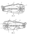
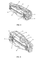
- the multipurpose tool 20 may be configured such that the handles 22 are adapted for relative movement between an open position as shown in Figures 1-2 and a closed position as shown in Figures 3-6 and discussed hereinafter.
- the multipurpose tool has a compact form factor in the closed position so as to facilitate transport and storage of the multipurpose tool. While the multipurpose tool is more expansive in the open position, one or more of the tool members of the multipurpose tool are accessible and capable of being utilized in the open position, even though those same tool member(s) are stowed and generally inaccessible in the closed position.
- a multipurpose tool 20 of one embodiment may include first and second handles 22 that are connected to the opposed jaws 24 of a tool member 26 having pivotable jaws, such as the pliers of the illustrated embodiment.
- the handles In the open configuration, the handles may be moved toward one another in order to close the jaws of the pliers and away from one another in order to open the jaws of the pliers.
- the jaws of the pliers are configured to contact one another once the jaws are in a fully opened position in order to prevent further opening of the jaws.
- the handles can be pivoted relative to the respective jaws in order to transition from the open position as shown in Figures 1-2 to the closed position as shown in Figures 3-6 .
- the handles 22 may transition from the closed position shown in Figures 3-6 to the open position shown in Figures 1-2 by pulling the handles away from one another and rotating the handles about the opposed jaws 24.
- the multipurpose tool 20 can include a variety of tool members.
- the multipurpose tool can include a tool member 26 having pivotable jaws 24, such as the pliers described above.
- the tool member having pivotable jaws can also include wire cutters and/or wire strippers, or scissors, if desired.
- the multipurpose tool of the embodiment depicted in Figures 1-6 includes a screwdriver 35, e.g., a Phillips screwdriver, scissors 36, a saw 38, and optionally a knife blade 30 carried by the handles 22.
- the screwdriver, the scissors, the saw, and the knife blade may be rotatably connected to the respective handles.
- the knife blade (as well as the saw and scissors) can be unfolded to a deployed position as shown in Figure 14 , particularly in instances in which the multipurpose tool is in the closed configuration.
- the knife blade can define an opening 70, typically opposite the cutting edge 72, that a user can grasp in order to rotate the knife blade outwardly away from the handle 22.
- the scale or sidewall 28 that is attached or otherwise integral to the frame of the respective handle covers the cutting edge of the knife blade while the knife blade is in a folded position.
- the multipurpose tool 20 can also include additional tool members 74, such as a screwdriver, bit driver, bottle opener, can opener, saw, razor, tweezers, gut hook or the like, that are folded into the channel defined by a handle 22.
- additional tool members 74 such as a screwdriver, bit driver, bottle opener, can opener, saw, razor, tweezers, gut hook or the like, that are folded into the channel defined by a handle 22.
- An assembled tool may be provided to the user with a separate tool member that has not yet been assembled with the remainder of the tool, but that the user can install into the tool if desired.
- a user may utilize the tool without the separate tool member if the user does not have any use for the separate tool member and, instead, desires a lighter and less complex tool.
- the user may install the separate tool member so as to add its functionality to that of the multipurpose tool.
- the separate tool member may include, but is not limited to, for example, a knife blade.
- the tool is provided with an opening or channel defined by the handle and configured to receive the separate tool member.
- the opening or cavity in the handle of the assembled tool can be left empty when the separate tool member is not installed, in some instances, it may be desirable to insert a temporary filler or cover (e.g., a plastic or metal piece) over or within the cavity that can be removed prior to installing the separate tool member.
- a temporary filler or cover e.g., a plastic or metal piece
- the tool includes an axle 34 upon which the separate tool member (and in some embodiments other tool member(s)) is rotatably mounted in an instance in which a user wishes to install the separate tool member in the multipurpose tool.
- the separate tool member has a tang 52 with an open slot 50, as shown in Figure 11 .
- the open slot 50 may be configured in various manners, the open slot of the tang of the illustrated embodiment has a circularly shaped portion 56 concentric to the axis of rotation of the installed tool member with flat surfaces 54 on either side of the slot defining an opening along one edge of the separate tool member.
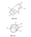
- the axle may be configured in various manners, but, in the illustrated embodiment depicted in Figures 12 and 13 , the axle has a concentric surface 60 with at least one portion of the surface having a reduced diameter relative to the other surfaces.
- the axle may include a larger first end having a pair of opposed flat surfaces 57 and a cylindrical portion extending outward from the larger first end that also has a pair of flat surfaces 58 positioned on opposite sides from each other.
- the flat surfaces 58 on the cylindrical portion interface with the handle 22 and the flat surfaces 57 on the larger first end interface with the tool member, such as a knife blade, so as to define at least one relative position between the axle 34 and the open slot 50 of the separate tool member with enough clearance to allow the open slot of the separate tool member to slide onto the axle (with the open slot being unable to be slid onto the axle in all other orientations of the axle).
- the tool member such as a knife blade
- the separate tool member is required to have a corresponding relative position, that is, a predefined installation position, to the handle of the tool (so as to create the specific relative position between the open slot and the axle) in order to install the separate tool member in the tool.
- a predefined installation position may require the separate tool member to be positioned substantially orthogonal to the handle.
- the separate tool member When the slots of the tang are aligned with the flats of the axle and the tang of the tool member is slid onto the axle, the separate tool member is retained on the axle as a result of the separate tool member engaging a lock feature 44 of the tool, as described below.
- the separate tool member also has a retention feature on at least one side which is engaged by a spring loaded lock, such as a liner lock, a frame lock, etc., to retain the tool member within the tool following installation of the separate tool member.
- the retention feature may be configured in various manners, but, in the illustrated embodiment, is a concentric step feature 46, such as a coined step feature, as shown in Figure 11 .
- the step feature 46 is located on the tang 52 of the tool member, such as about the periphery of the tang, is concentric to the axis of rotation of the installed tool member and extends around a portion of the tang, but not the entire circumference of the tang.
- the step feature 46 may include on at least one end a ramp 76 for engaging with the lock during rotation of the separate tool member.
- the lock is disposed within, e.g., snaps into, the step feature 46 so as to retain the separate tool member.
- the tool member continues to engage with the spring loaded lock 44 during rotation from an open to a closed position.
- the lock 44 as shown in Figure 10 , includes a retention edge 42 designed to slide along the step feature as the separate tool member rotates about the axle 34 from an open to a closed position.
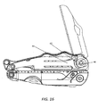
- Figure 14 shows that when the installed separate tool member is in the open position, the step feature 46 of the separate tool member is not engaged with the retention edge of the lock 42.
- the retention edge of the lock 42 is positioned so as to engage an end surface 48 of the tool member to retain the tool member in the open position.
- the lock must be displaced relative to the tool member in order to close the tool member.
- the tool may include an actuation member, such as a tab 32 as described below, to permit a user to apply the force necessary to displace the lock and permit rotational closing of the tool member.
- the retention edge of the lock 42 slides along the step feature 46 of the separate tool member, as shown in Figure 15 .
- the lock slides along the ramp 76 of the step feature that smoothly transitions from step feature (having a reduced thickness) to the main body of the tang (having a greater thickness), thereby disengaging the lock from the edge of the tool member.
- the ramp transitions along the step and tapers off at the end of the step which allows the lock to fall off the step feature.
- the user will have the option to install a separate tool member onto the tool following purchase and/or delivery of the tool.
- the user can tailor the tool as desired.
- a method of installing a tool member onto an already assembled tool is provided. If a filler or cover has been inserted into the opening on the handle, it should be removed prior to installation of the separate tool member.
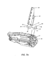
- the tool member is aligned such that the open slot 50 on the tang 52 of the tool member slides onto the axle 34 of the handle, as illustrated in Figure 7a .
- the separate tool member is pushed through the load of the spring loaded lock 44 until the retention feature of the tool member engages with the lock of the tool and snaps into place on the axle of the tool.
- a guard may be carried by the separate tool member during installation.
- a blade guard 68 may be used, such as one shown in Figure 7a , in order to cover a sharp cutting surface to prevent inadvertent contact therewith during the installation process.
- the blade guard 68 may include or carry installation instructions, such as engraved or molded into the blade guard or attached to the blade guard. The blade guard 68 not only allows for user safety during installation, but also guides the open slot 50 on the tang 52 of the knife blade 30 onto the axle 34 of the tool.
- the knife guard 68 guides the tang 52 of the knife blade by controlling the depth and angle of the slot 50 defined by the tang to the depth and angle of the axle 34.
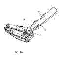
- the blade guard 68 of an example embodiment may have an edge thickness that corresponds to the corresponding edge of the scale. When these edges of the blade guard 68 and the scale are held flush, the tang 52 of the knife blade 30 and the axle 34 are properly oriented to permit the knife blade to be slid into place, as shown in Figures 7b and 7c .
- Figure 7c treats the handle and scale as translucent such that internal components of the tool including the tang 52 of the knife blade 30 and the axle 34 may be visible for purposes of illustration.
- the blade guard 68 allows for at least one, but not every, relative position of the separate tool member to the handle, that is, a predefined installation position such as in an instance in which the separate tool member extends orthogonally relative to the handle, to have enough clearance with respect to the handle to allow the separate tool member to slide onto the axle so it can then be captured by the lock and folded into the opening in the handle.
- the blade guard may facilitate installation of the separate tool member in an intuitive manner.
- the blade guard 68 may be formed of various materials, but, in one embodiment, is formed of a plastic material.
- the blade guard may be removed from the separate tool material prior to or following installation of the separate tool member to the tool. In this regard, the blade guard may be slid off of or otherwise removed from the tool member.
- the blade guard may be configured such that rotation of the separate tool member from the predefined installation position to the closed position may cause the blade guard to be disengaged from the separate tool member.
- the tool member of a tool When the tool member of a tool is in the open position, the tool member may be locked open, as depicted in Figure 14 .
- the lock mechanism such as a liner lock, frame lock, etc.
- the lock 44 may be displaced so as to permit folding of the tool member by pressing an actuation mechanism, such as a tab 32 or tabs, on the tool.
- the tool member of the illustrated embodiment has a lock release mechanism that allows the user to fold a tool member into the tool without placing fingers in the path of travel of the tool member.
- At least one of the handles 22 of the tool including at least the handle that includes the lock mechanism 44 has a scale 28 that defines the exterior surface of the handle.
- the scale may be plastic.
- the actuation mechanism such as a tab 32, may be cut into or otherwise formed by the scale 28.
- the tab 32 is in operable engagement with the lock 44 and is configured for actuation, e.g., deflection, by the user to permit the lock to be displaced and the tool member permitted to be folded into the handle.
- the user can push in the tab 32 with a finger in order to release the lock.
- the lock includes or is otherwise associated with a dogleg 40, as depicted in Figure 10 .
- the tab 32 is also in operable engagement with the dogleg 40, such that deflection of the tab causes a corresponding movement of the dogleg and, in turn, deflection of the lock, thereby allowing the tab to push the lock out of the path of the tool member and permitting the tool member to be folded from the open to the closed position.
- the tab(s) 32 may be positioned on the tool such that the tab(s) is closer to the axle 34 upon which the tool member rotates than to an opposite end of the handle.
- the tabs may include a pair of tabs on the scales 28 on opposite sides of at least one of the handles.
- the tabs may also include one or a pair of tabs on both handles. Each tab is configured to deflect a lock carried by the respective handle so as to unlock a tool member and to permit the tool member to be folded into the respective handle.
Landscapes
- Engineering & Computer Science (AREA)
- Mechanical Engineering (AREA)
- Knives (AREA)
- Workshop Equipment, Work Benches, Supports, Or Storage Means (AREA)
Applications Claiming Priority (1)
| Application Number | Priority Date | Filing Date | Title |
|---|---|---|---|
| US14/148,170 US9440346B2 (en) | 2014-01-06 | 2014-01-06 | Tool having a tool member configured for subsequent installation |
Publications (3)
| Publication Number | Publication Date |
|---|---|
| EP2898995A2 true EP2898995A2 (fr) | 2015-07-29 |
| EP2898995A3 EP2898995A3 (fr) | 2015-11-04 |
| EP2898995B1 EP2898995B1 (fr) | 2020-04-15 |
Family
ID=52020887
Family Applications (1)
| Application Number | Title | Priority Date | Filing Date |
|---|---|---|---|
| EP14004048.6A Active EP2898995B1 (fr) | 2014-01-06 | 2014-12-01 | Outil pourvu d'un élément d'outil configuré pour installation ultérieure |
Country Status (4)
| Country | Link |
|---|---|
| US (1) | US9440346B2 (fr) |
| EP (1) | EP2898995B1 (fr) |
| CN (1) | CN104760028B (fr) |
| AU (1) | AU2014246590B2 (fr) |
Families Citing this family (5)
| Publication number | Priority date | Publication date | Assignee | Title |
|---|---|---|---|---|
| CN112654464B (zh) | 2018-09-07 | 2023-05-30 | 迈克尔·奥唐纳 | 模块化工具装置 |
| GB201902972D0 (en) * | 2019-03-05 | 2019-04-17 | Booth Douglas Alexander | Apparatus comprising a plurality of different tools |
| US11999040B2 (en) * | 2020-03-23 | 2024-06-04 | Chance Granado | Hacksaw multitool |
| USD941655S1 (en) * | 2021-03-08 | 2022-01-25 | Pingxiang Jiancheng Technology Co., Ltd. | Multi-functional tool |
| USD994457S1 (en) * | 2021-03-15 | 2023-08-08 | Miaoli Feng | Multifunctional tool |
Family Cites Families (35)
| Publication number | Priority date | Publication date | Assignee | Title |
|---|---|---|---|---|
| US1413954A (en) * | 1920-07-15 | 1922-04-25 | Henry D Ball | Knife |
| US5142721A (en) | 1991-03-08 | 1992-09-01 | Fiskars Oy Ab | Pocket tool with retractable jaws |
| US5212844A (en) | 1991-03-08 | 1993-05-25 | Fiskars Oy Ab | Pocket tool with retractable jaws |
| US5351761A (en) | 1993-07-22 | 1994-10-04 | Henthorn Clyde E | Field stone collection apparatus |
| US5511310A (en) | 1994-08-18 | 1996-04-30 | Fiskars Inc. | Folding knife |
| USD366408S (en) | 1994-08-18 | 1996-01-23 | Fiskars Inc. | Folding knife |
| US5765247A (en) | 1996-01-11 | 1998-06-16 | Buck Knives, Inc. | Hand tool with multiple locking blades controlled by a single locking mechanism and release |
| EP1354668B1 (fr) * | 1996-10-29 | 2008-05-21 | Victorinox | Outil polyvalent |
| US6014787A (en) | 1997-10-30 | 2000-01-18 | Leatherman Tool Group, Inc. | Multipurpose folding tool with easily accessible outer blades |
| USD427501S (en) | 1999-01-29 | 2000-07-04 | Leatherman Tool Group, Inc. | Blade latch lever for a multipurpose folding tool |
| US6088861A (en) | 1999-01-29 | 2000-07-18 | Buck Knives, Inc. | Tool with locking fold-out implements |
| USD429621S (en) | 2000-01-12 | 2000-08-22 | Leatherman Tool Group, Inc. | Portion of a latch release operating lever for a hand tool |
| US6510767B1 (en) | 2000-01-12 | 2003-01-28 | Leatherman Tool Goup, Inc. | Folding multipurpose tool including blade lock release mechanism |
| USD436514S1 (en) | 2000-01-12 | 2001-01-23 | Leatherman Tool Group, Inc. | Handle and latch release lever for a multipurpose hand tool |
| US6622328B2 (en) | 2000-10-31 | 2003-09-23 | Leatherman Tool Group, Inc. | Folding multipurpose pocket tool with floating springs |
| US6675484B2 (en) * | 2001-07-30 | 2004-01-13 | Mentor Group Llc | Folding tool locking mechanism |
| US7182001B2 (en) | 2002-01-30 | 2007-02-27 | Leatherman Tool Group, Inc. | Tool frame member including spring |
| US6675419B2 (en) * | 2002-01-30 | 2004-01-13 | Leatherman Tool Group, Inc. | Removable tool element for inclusion in a folding tool |
| US7347128B2 (en) | 2004-01-13 | 2008-03-25 | Leatherman Tool Group, Inc. | Multipurpose folding tool with tool bit holder and blade lock |
| USD496847S1 (en) | 2004-01-13 | 2004-10-05 | Leatherman Tool Group, Inc. | Side plate for a tool handle, with an indented area |
| CA2491948C (fr) | 2004-01-13 | 2009-07-14 | Leatherman Tool Group, Inc. | Outil pliant polyvalent avec porte-element d'outil et verrou a lame |
| USD496846S1 (en) | 2004-01-13 | 2004-10-05 | Leatherman Tool Group, Inc. | Side plate for a handle |
| USD497096S1 (en) | 2004-01-13 | 2004-10-12 | Leatherman Tool Group, Inc. | Side plate for a tool handle |
| USD497095S1 (en) | 2004-01-13 | 2004-10-12 | Leatherman Tool Group, Inc. | Side plate for a handle, with an indented area |
| US8028419B2 (en) * | 2005-05-19 | 2011-10-04 | Gb Ii Corporation | Folding knife or tool |
| US7353736B2 (en) * | 2005-07-27 | 2008-04-08 | Leatherman Tool Group, Inc. | Enhanced multi-function hand tool |
| US7654004B2 (en) | 2006-04-25 | 2010-02-02 | Leatherman Tool Group, Inc. | Hand tool having fixed and rotatable implements and an associated locking mechanism |
| WO2009079482A2 (fr) * | 2007-12-14 | 2009-06-25 | Josh Downes | Dispositif de rangement de clé |
| US8161653B2 (en) | 2007-11-12 | 2012-04-24 | Leatherman Tool Group, Inc. | Folding tool having a rotatable locking mechanism |
| USD595103S1 (en) | 2008-05-29 | 2009-06-30 | Leatherman Tool Group, Inc. | Scales for knives, hand tools, and the like |
| USD595440S1 (en) | 2008-06-20 | 2009-06-30 | Leatherman Tool Group, Inc. | Flashlight |
| USD596556S1 (en) | 2008-06-24 | 2009-07-21 | Toyo Tire & Rubber Co., Ltd. | Automobile tire |
| US8528451B2 (en) | 2009-11-24 | 2013-09-10 | Leatherman Tool Group, Inc. | Tool having an integral carabiner |
| US8166850B2 (en) | 2009-12-18 | 2012-05-01 | Leatherman Tool Group, Inc. | Multipurpose tool |
| US9095970B2 (en) | 2010-12-17 | 2015-08-04 | Leatherman Tool Group, Inc. | Multipurpose tool configured to facilitate access to individual tool members |
-
2014
- 2014-01-06 US US14/148,170 patent/US9440346B2/en active Active
- 2014-10-10 AU AU2014246590A patent/AU2014246590B2/en active Active
- 2014-11-14 CN CN201410648206.5A patent/CN104760028B/zh active Active
- 2014-12-01 EP EP14004048.6A patent/EP2898995B1/fr active Active
Non-Patent Citations (1)
| Title |
|---|
| None |
Also Published As
| Publication number | Publication date |
|---|---|
| EP2898995B1 (fr) | 2020-04-15 |
| CN104760028B (zh) | 2017-11-17 |
| AU2014246590A1 (en) | 2015-07-23 |
| CN104760028A (zh) | 2015-07-08 |
| US9440346B2 (en) | 2016-09-13 |
| AU2014246590B2 (en) | 2017-02-23 |
| US20150190915A1 (en) | 2015-07-09 |
| EP2898995A3 (fr) | 2015-11-04 |
Similar Documents
| Publication | Publication Date | Title |
|---|---|---|
| AU2021202402B2 (en) | Multipurpose tool having accessible tool members | |
| US9095970B2 (en) | Multipurpose tool configured to facilitate access to individual tool members | |
| US7712399B2 (en) | Tool and associated bit driver | |
| EP2898995B1 (fr) | Outil pourvu d'un élément d'outil configuré pour installation ultérieure | |
| EP2324962B1 (fr) | Outil doté d'un mousqueton intégré | |
| AU2008200108B2 (en) | Multipurpose tool | |
| US11623334B2 (en) | Tool having one or more rotatable tool members | |
| HK40073958A (en) | Tool having one or more rotatable tool members | |
| HK40073958B (en) | Tool having one or more rotatable tool members | |
| HK40016924A (en) | Tool having one or more rotatable tool members | |
| HK40016924B (en) | Tool having one or more rotatable tool members | |
| HK1250502B (en) | Multipurpose tool having accessible tool members | |
| HK40024428A (en) | Multipurpose tool having accessible tool members | |
| HK40024428B (en) | Multipurpose tool having accessible tool members |
Legal Events
| Date | Code | Title | Description |
|---|---|---|---|
| PUAI | Public reference made under article 153(3) epc to a published international application that has entered the european phase |
Free format text: ORIGINAL CODE: 0009012 |
|
| 17P | Request for examination filed |
Effective date: 20141201 |
|
| AK | Designated contracting states |
Kind code of ref document: A2 Designated state(s): AL AT BE BG CH CY CZ DE DK EE ES FI FR GB GR HR HU IE IS IT LI LT LU LV MC MK MT NL NO PL PT RO RS SE SI SK SM TR |
|
| AX | Request for extension of the european patent |
Extension state: BA ME |
|
| PUAL | Search report despatched |
Free format text: ORIGINAL CODE: 0009013 |
|
| AK | Designated contracting states |
Kind code of ref document: A3 Designated state(s): AL AT BE BG CH CY CZ DE DK EE ES FI FR GB GR HR HU IE IS IT LI LT LU LV MC MK MT NL NO PL PT RO RS SE SI SK SM TR |
|
| AX | Request for extension of the european patent |
Extension state: BA ME |
|
| RIC1 | Information provided on ipc code assigned before grant |
Ipc: B25F 1/04 20060101AFI20150928BHEP |
|
| 17P | Request for examination filed |
Effective date: 20160504 |
|
| RBV | Designated contracting states (corrected) |
Designated state(s): AL AT BE BG CH CY CZ DE DK EE ES FI FR GB GR HR HU IE IS IT LI LT LU LV MC MK MT NL NO PL PT RO RS SE SI SK SM TR |
|
| GRAP | Despatch of communication of intention to grant a patent |
Free format text: ORIGINAL CODE: EPIDOSNIGR1 |
|
| STAA | Information on the status of an ep patent application or granted ep patent |
Free format text: STATUS: GRANT OF PATENT IS INTENDED |
|
| INTG | Intention to grant announced |
Effective date: 20191115 |
|
| GRAS | Grant fee paid |
Free format text: ORIGINAL CODE: EPIDOSNIGR3 |
|
| GRAA | (expected) grant |
Free format text: ORIGINAL CODE: 0009210 |
|
| STAA | Information on the status of an ep patent application or granted ep patent |
Free format text: STATUS: THE PATENT HAS BEEN GRANTED |
|
| AK | Designated contracting states |
Kind code of ref document: B1 Designated state(s): AL AT BE BG CH CY CZ DE DK EE ES FI FR GB GR HR HU IE IS IT LI LT LU LV MC MK MT NL NO PL PT RO RS SE SI SK SM TR |
|
| REG | Reference to a national code |
Ref country code: CH Ref legal event code: EP |
|
| REG | Reference to a national code |
Ref country code: DE Ref legal event code: R096 Ref document number: 602014063700 Country of ref document: DE |
|
| REG | Reference to a national code |
Ref country code: IE Ref legal event code: FG4D |
|
| REG | Reference to a national code |
Ref country code: AT Ref legal event code: REF Ref document number: 1256703 Country of ref document: AT Kind code of ref document: T Effective date: 20200515 |
|
| REG | Reference to a national code |
Ref country code: NL Ref legal event code: MP Effective date: 20200415 |
|
| REG | Reference to a national code |
Ref country code: LT Ref legal event code: MG4D |
|
| PG25 | Lapsed in a contracting state [announced via postgrant information from national office to epo] |
Ref country code: NO Free format text: LAPSE BECAUSE OF FAILURE TO SUBMIT A TRANSLATION OF THE DESCRIPTION OR TO PAY THE FEE WITHIN THE PRESCRIBED TIME-LIMIT Effective date: 20200715 Ref country code: GR Free format text: LAPSE BECAUSE OF FAILURE TO SUBMIT A TRANSLATION OF THE DESCRIPTION OR TO PAY THE FEE WITHIN THE PRESCRIBED TIME-LIMIT Effective date: 20200716 Ref country code: FI Free format text: LAPSE BECAUSE OF FAILURE TO SUBMIT A TRANSLATION OF THE DESCRIPTION OR TO PAY THE FEE WITHIN THE PRESCRIBED TIME-LIMIT Effective date: 20200415 Ref country code: IS Free format text: LAPSE BECAUSE OF FAILURE TO SUBMIT A TRANSLATION OF THE DESCRIPTION OR TO PAY THE FEE WITHIN THE PRESCRIBED TIME-LIMIT Effective date: 20200815 Ref country code: PT Free format text: LAPSE BECAUSE OF FAILURE TO SUBMIT A TRANSLATION OF THE DESCRIPTION OR TO PAY THE FEE WITHIN THE PRESCRIBED TIME-LIMIT Effective date: 20200817 Ref country code: LT Free format text: LAPSE BECAUSE OF FAILURE TO SUBMIT A TRANSLATION OF THE DESCRIPTION OR TO PAY THE FEE WITHIN THE PRESCRIBED TIME-LIMIT Effective date: 20200415 Ref country code: SE Free format text: LAPSE BECAUSE OF FAILURE TO SUBMIT A TRANSLATION OF THE DESCRIPTION OR TO PAY THE FEE WITHIN THE PRESCRIBED TIME-LIMIT Effective date: 20200415 Ref country code: NL Free format text: LAPSE BECAUSE OF FAILURE TO SUBMIT A TRANSLATION OF THE DESCRIPTION OR TO PAY THE FEE WITHIN THE PRESCRIBED TIME-LIMIT Effective date: 20200415 |
|
| REG | Reference to a national code |
Ref country code: AT Ref legal event code: MK05 Ref document number: 1256703 Country of ref document: AT Kind code of ref document: T Effective date: 20200415 |
|
| PG25 | Lapsed in a contracting state [announced via postgrant information from national office to epo] |
Ref country code: HR Free format text: LAPSE BECAUSE OF FAILURE TO SUBMIT A TRANSLATION OF THE DESCRIPTION OR TO PAY THE FEE WITHIN THE PRESCRIBED TIME-LIMIT Effective date: 20200415 Ref country code: BG Free format text: LAPSE BECAUSE OF FAILURE TO SUBMIT A TRANSLATION OF THE DESCRIPTION OR TO PAY THE FEE WITHIN THE PRESCRIBED TIME-LIMIT Effective date: 20200715 Ref country code: RS Free format text: LAPSE BECAUSE OF FAILURE TO SUBMIT A TRANSLATION OF THE DESCRIPTION OR TO PAY THE FEE WITHIN THE PRESCRIBED TIME-LIMIT Effective date: 20200415 Ref country code: LV Free format text: LAPSE BECAUSE OF FAILURE TO SUBMIT A TRANSLATION OF THE DESCRIPTION OR TO PAY THE FEE WITHIN THE PRESCRIBED TIME-LIMIT Effective date: 20200415 |
|
| PG25 | Lapsed in a contracting state [announced via postgrant information from national office to epo] |
Ref country code: AL Free format text: LAPSE BECAUSE OF FAILURE TO SUBMIT A TRANSLATION OF THE DESCRIPTION OR TO PAY THE FEE WITHIN THE PRESCRIBED TIME-LIMIT Effective date: 20200415 |
|
| REG | Reference to a national code |
Ref country code: DE Ref legal event code: R097 Ref document number: 602014063700 Country of ref document: DE |
|
| PG25 | Lapsed in a contracting state [announced via postgrant information from national office to epo] |
Ref country code: DK Free format text: LAPSE BECAUSE OF FAILURE TO SUBMIT A TRANSLATION OF THE DESCRIPTION OR TO PAY THE FEE WITHIN THE PRESCRIBED TIME-LIMIT Effective date: 20200415 Ref country code: EE Free format text: LAPSE BECAUSE OF FAILURE TO SUBMIT A TRANSLATION OF THE DESCRIPTION OR TO PAY THE FEE WITHIN THE PRESCRIBED TIME-LIMIT Effective date: 20200415 Ref country code: AT Free format text: LAPSE BECAUSE OF FAILURE TO SUBMIT A TRANSLATION OF THE DESCRIPTION OR TO PAY THE FEE WITHIN THE PRESCRIBED TIME-LIMIT Effective date: 20200415 Ref country code: RO Free format text: LAPSE BECAUSE OF FAILURE TO SUBMIT A TRANSLATION OF THE DESCRIPTION OR TO PAY THE FEE WITHIN THE PRESCRIBED TIME-LIMIT Effective date: 20200415 Ref country code: SM Free format text: LAPSE BECAUSE OF FAILURE TO SUBMIT A TRANSLATION OF THE DESCRIPTION OR TO PAY THE FEE WITHIN THE PRESCRIBED TIME-LIMIT Effective date: 20200415 Ref country code: ES Free format text: LAPSE BECAUSE OF FAILURE TO SUBMIT A TRANSLATION OF THE DESCRIPTION OR TO PAY THE FEE WITHIN THE PRESCRIBED TIME-LIMIT Effective date: 20200415 Ref country code: CZ Free format text: LAPSE BECAUSE OF FAILURE TO SUBMIT A TRANSLATION OF THE DESCRIPTION OR TO PAY THE FEE WITHIN THE PRESCRIBED TIME-LIMIT Effective date: 20200415 Ref country code: IT Free format text: LAPSE BECAUSE OF FAILURE TO SUBMIT A TRANSLATION OF THE DESCRIPTION OR TO PAY THE FEE WITHIN THE PRESCRIBED TIME-LIMIT Effective date: 20200415 |
|
| PLBE | No opposition filed within time limit |
Free format text: ORIGINAL CODE: 0009261 |
|
| STAA | Information on the status of an ep patent application or granted ep patent |
Free format text: STATUS: NO OPPOSITION FILED WITHIN TIME LIMIT |
|
| PG25 | Lapsed in a contracting state [announced via postgrant information from national office to epo] |
Ref country code: PL Free format text: LAPSE BECAUSE OF FAILURE TO SUBMIT A TRANSLATION OF THE DESCRIPTION OR TO PAY THE FEE WITHIN THE PRESCRIBED TIME-LIMIT Effective date: 20200415 Ref country code: SK Free format text: LAPSE BECAUSE OF FAILURE TO SUBMIT A TRANSLATION OF THE DESCRIPTION OR TO PAY THE FEE WITHIN THE PRESCRIBED TIME-LIMIT Effective date: 20200415 |
|
| 26N | No opposition filed |
Effective date: 20210118 |
|
| PG25 | Lapsed in a contracting state [announced via postgrant information from national office to epo] |
Ref country code: SI Free format text: LAPSE BECAUSE OF FAILURE TO SUBMIT A TRANSLATION OF THE DESCRIPTION OR TO PAY THE FEE WITHIN THE PRESCRIBED TIME-LIMIT Effective date: 20200415 |
|
| REG | Reference to a national code |
Ref country code: CH Ref legal event code: PL |
|
| PG25 | Lapsed in a contracting state [announced via postgrant information from national office to epo] |
Ref country code: MC Free format text: LAPSE BECAUSE OF FAILURE TO SUBMIT A TRANSLATION OF THE DESCRIPTION OR TO PAY THE FEE WITHIN THE PRESCRIBED TIME-LIMIT Effective date: 20200415 |
|
| REG | Reference to a national code |
Ref country code: BE Ref legal event code: MM Effective date: 20201231 |
|
| PG25 | Lapsed in a contracting state [announced via postgrant information from national office to epo] |
Ref country code: LU Free format text: LAPSE BECAUSE OF NON-PAYMENT OF DUE FEES Effective date: 20201201 Ref country code: IE Free format text: LAPSE BECAUSE OF NON-PAYMENT OF DUE FEES Effective date: 20201201 |
|
| PG25 | Lapsed in a contracting state [announced via postgrant information from national office to epo] |
Ref country code: LI Free format text: LAPSE BECAUSE OF NON-PAYMENT OF DUE FEES Effective date: 20201231 Ref country code: CH Free format text: LAPSE BECAUSE OF NON-PAYMENT OF DUE FEES Effective date: 20201231 |
|
| PG25 | Lapsed in a contracting state [announced via postgrant information from national office to epo] |
Ref country code: TR Free format text: LAPSE BECAUSE OF FAILURE TO SUBMIT A TRANSLATION OF THE DESCRIPTION OR TO PAY THE FEE WITHIN THE PRESCRIBED TIME-LIMIT Effective date: 20200415 Ref country code: MT Free format text: LAPSE BECAUSE OF FAILURE TO SUBMIT A TRANSLATION OF THE DESCRIPTION OR TO PAY THE FEE WITHIN THE PRESCRIBED TIME-LIMIT Effective date: 20200415 Ref country code: CY Free format text: LAPSE BECAUSE OF FAILURE TO SUBMIT A TRANSLATION OF THE DESCRIPTION OR TO PAY THE FEE WITHIN THE PRESCRIBED TIME-LIMIT Effective date: 20200415 |
|
| PG25 | Lapsed in a contracting state [announced via postgrant information from national office to epo] |
Ref country code: MK Free format text: LAPSE BECAUSE OF FAILURE TO SUBMIT A TRANSLATION OF THE DESCRIPTION OR TO PAY THE FEE WITHIN THE PRESCRIBED TIME-LIMIT Effective date: 20200415 |
|
| PG25 | Lapsed in a contracting state [announced via postgrant information from national office to epo] |
Ref country code: BE Free format text: LAPSE BECAUSE OF NON-PAYMENT OF DUE FEES Effective date: 20201231 |
|
| PGFP | Annual fee paid to national office [announced via postgrant information from national office to epo] |
Ref country code: GB Payment date: 20251229 Year of fee payment: 12 |
|
| PGFP | Annual fee paid to national office [announced via postgrant information from national office to epo] |
Ref country code: FR Payment date: 20251226 Year of fee payment: 12 |
|
| PGFP | Annual fee paid to national office [announced via postgrant information from national office to epo] |
Ref country code: DE Payment date: 20251229 Year of fee payment: 12 |