EP2899043A1 - Accumulateur à piston, essieu de véhicule et système de suspension de véhicule doté d'un tel accumulateur à piston - Google Patents
Accumulateur à piston, essieu de véhicule et système de suspension de véhicule doté d'un tel accumulateur à piston Download PDFInfo
- Publication number
- EP2899043A1 EP2899043A1 EP14152197.1A EP14152197A EP2899043A1 EP 2899043 A1 EP2899043 A1 EP 2899043A1 EP 14152197 A EP14152197 A EP 14152197A EP 2899043 A1 EP2899043 A1 EP 2899043A1
- Authority
- EP
- European Patent Office
- Prior art keywords
- axle
- piston
- vehicle
- inner bore
- cylinder
- Prior art date
- Legal status (The legal status is an assumption and is not a legal conclusion. Google has not performed a legal analysis and makes no representation as to the accuracy of the status listed.)
- Granted
Links
Images


Classifications
-
- B—PERFORMING OPERATIONS; TRANSPORTING
- B60—VEHICLES IN GENERAL
- B60G—VEHICLE SUSPENSION ARRANGEMENTS
- B60G11/00—Resilient suspensions characterised by arrangement, location or kind of springs
- B60G11/26—Resilient suspensions characterised by arrangement, location or kind of springs having fluid springs only, e.g. hydropneumatic springs
- B60G11/30—Resilient suspensions characterised by arrangement, location or kind of springs having fluid springs only, e.g. hydropneumatic springs having pressure fluid accumulator therefor, e.g. accumulator arranged in vehicle frame
-
- B—PERFORMING OPERATIONS; TRANSPORTING
- B60—VEHICLES IN GENERAL
- B60G—VEHICLE SUSPENSION ARRANGEMENTS
- B60G9/00—Resilient suspensions of a rigid axle or axle housing for two or more wheels
-
- B—PERFORMING OPERATIONS; TRANSPORTING
- B60—VEHICLES IN GENERAL
- B60G—VEHICLE SUSPENSION ARRANGEMENTS
- B60G2202/00—Indexing codes relating to the type of spring, damper or actuator
- B60G2202/10—Type of spring
- B60G2202/15—Fluid spring
- B60G2202/154—Fluid spring with an accumulator
-
- B—PERFORMING OPERATIONS; TRANSPORTING
- B60—VEHICLES IN GENERAL
- B60G—VEHICLE SUSPENSION ARRANGEMENTS
- B60G2204/00—Indexing codes related to suspensions per se or to auxiliary parts
- B60G2204/10—Mounting of suspension elements
- B60G2204/12—Mounting of springs or dampers
- B60G2204/13—Mounting of springs or dampers with the spring, i.e. coil spring, or damper horizontally mounted
-
- B—PERFORMING OPERATIONS; TRANSPORTING
- B60—VEHICLES IN GENERAL
- B60G—VEHICLE SUSPENSION ARRANGEMENTS
- B60G2206/00—Indexing codes related to the manufacturing of suspensions: constructional features, the materials used, procedures or tools
- B60G2206/01—Constructional features of suspension elements, e.g. arms, dampers, springs
- B60G2206/30—Constructional features of rigid axles
-
- B—PERFORMING OPERATIONS; TRANSPORTING
- B60—VEHICLES IN GENERAL
- B60G—VEHICLE SUSPENSION ARRANGEMENTS
- B60G2206/00—Indexing codes related to the manufacturing of suspensions: constructional features, the materials used, procedures or tools
- B60G2206/01—Constructional features of suspension elements, e.g. arms, dampers, springs
- B60G2206/30—Constructional features of rigid axles
- B60G2206/32—Hollow cross section
Definitions
- the present invention relates to a, in particular hydropneumatic, piston accumulator, in particular for vehicle suspension systems, comprising a storage housing and in the storage housing in the direction of a housing longitudinally slidably guided separating piston in the housing a storage space for a hydraulic medium from a spring element, in particular a compressible medium , containing pressure chamber separates and filling openings for the medium or the two media.
- the invention further relates to a vehicle axle with such a piston accumulator and a vehicle suspension system with such a vehicle axle.
- the vehicle axle serves in particular as a vehicle axle for trailers.
- Such a hydropneumatic piston accumulator is z. B. from the DE 20 2009 018 583 U1 known.
- Such a piston accumulator has the disadvantage that additional space in the axle area is required and the vehicle weight is increased by this additional piston accumulator. In addition, increase the production cost of the vehicle by the additional piston accumulator.
- the present invention is based on the object to provide a piston accumulator available that requires no additional space in the axle and by which the vehicle weight is not substantially increased. Further objects are the provision of a vehicle axle with such a piston accumulator and a vehicle suspension system with such a vehicle axle.
- the storage housing as axle body of a vehicle axle is formed with a circular cross-section inner bore, wherein in the inner bore of the separating piston is arranged.
- a vehicle axle with the axle body having a longitudinal axis, wherein the axle body has an axle tube with the circular cross-section in the inner bore.
- the axle body has at least one, preferably two, piston accumulators, the accumulator accumulator having the accumulator housing and the separating piston.
- the storage housing has a housing cylinder space and the separating piston is displaceably guided back and forth within the housing cylinder space and separates the housing cylinder space in the storage space for the hydraulic medium and a, in particular pneumatic spring element, containing pressure chamber.
- the separating piston according to the invention is displaceably guided within the inner bore of the axle tube.
- the housing cylinder space is thereby formed according to the invention by an inner bore portion of the inner bore of the axle tube.
- the storage enclosure is at least partially formed by the axle tube, in particular a pipe wall of the axle tube, or is part of the axle tube.
- the axle tube, in particular the tube wall of the axle tube, according to the invention forms part of the storage housing of the piston accumulator.
- the invention is based on the finding that the vehicle axle, which is present in the vehicle anyway, is used for receiving the separating piston and for forming the two spaces for the hydraulic medium and for the compressible medium, so that no additional components are required.
- the vehicle axle is therefore also the embodiment of the invention, since it is no longer subject to torsional stresses.
- the present invention is based on the recognition that the axle body can be made sufficiently rigid, so that an unobstructed longitudinal displacement of the separating piston is ensured within the axle body.
- the invention relates to a vehicle suspension system comprising at least one telescopic spring cylinder, wherein the telescopic spring cylinder a hollow cylinder in which in the cylinder longitudinal axis a piston is displaceably guided, which has a circumferentially sealed, led out of the Hohlyzylinder piston rod, wherein the piston separates a cylinder chamber from a piston rod enclosing the annular space, and a hydropneumatic piston accumulator according to the invention according to the characterizing part of Claim 1 is formed.
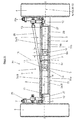
- a hydropneumatic piston accumulator 1 (according to the invention) Fig. 1-5 ) consists of a storage housing 2 and in the storage housing 2 in the direction of a housing longitudinal axis XX back and forth slidably guided separating piston 3.
- the storage housing 2 has an inner housing cylindrical space 2a, within which the separating piston 3, in particular free floating, is arranged.
- the housing cylinder space 2a has a cylinder axis 32, which corresponds to the housing longitudinal axis XX.
- the storage housing 2 is formed as part of a vehicle axle body 5 of a vehicle axle 31 which connects two opposite vehicle wheels 4. In the vehicle axle 31 is in particular a rigid axle.
- the elongatedzhouachsêt 5 has a longitudinal axis 5a, which corresponds to the axis of rotation of the axle 5 to be fastened to the vehicle wheels 4.
- thedeciachsêt 5 has an axle tube 11 with a pipe wall 29, the central pipe longitudinal axis 30 is coaxial with the longitudinal axis 5a and coaxial with the housing longitudinal axis X-X.
- Theffyachsêt 5, in particular the axle tube 11, has a circular in cross-section inner bore or inner recess 6, the bore axis 6a is coaxial with the tube longitudinal axis 30.
- the circular cross-section in the inner bore 6 is divided by an intermediate wall element 7 into two sub-spaces, each of which forms a circular cross-section in the inner bore portion 8, 9 of the inner bore 6.
- the intermediate wall element 7 divides the axle tube 11 into two axle tube sections 11a, 11b.
- the two inner bore sections 8, 9 and axle tube sections 11 a, 11 b are each fluidically separated from one another by the intermediate wall element 7.
- Each of the axle tube sections 11a, 11b has one of the two inner bore sections 8, 9.
- an inner bore section 8, 9 or axle tube section 11a, 11b also lies on another side of a central plane 15.
- the middle plane 15 is perpendicular to the longitudinal axis 5a and in the center arranged with respect to the longitudinal extent of the axle body 5.
- the axle body 5 is formed symmetrically to the center plane 15.
- a separating piston 3 is arranged in each case such that it is displaceably guided back and forth in the direction of the longitudinal axis 5a of the axle body 5 or the pipe longitudinal axis 30 and is also sealed circumferentially.
- the vehicle axle 31 in this case has two piston accumulators 1 according to the invention.
- the tube wall 29 in each case forms part of the accumulator housing 2 of each piston accumulator 1.
- the accumulator housing 2 of each piston accumulator 1 is designed in each case as part of the axle body 5.
- the separating piston 3 of the first inner bore section 8 divides the inner bore section 8 into a storage space 8a for a hydraulic medium and a pressure space 8b, into which a compressible medium can be filled or filled.
- each inner bore section 8, 9 forms the housing cylinder space 2 a of the storage housing 2.
- the axle tube 11 is made of metal, in particular steel.
- the axle body 5 is preferably produced from two individual hollow cylinders or tubes closed on one side by a bottom wall. These are set with their bottom walls against each other and the bottom walls welded together or otherwise firmly connected. The two bottom walls then form the intermediate wall element 7.
- the axle body 5 is closed at the end, that is to say at its two free, wheel-side axle body ends, by closure caps 12 ( Fig. 1 and 2 ).
- the closure caps 12 close the inner bore 6 or the inner bore sections 8, 9 in a pressure and media-tight manner.
- these closure caps 12 are detachably connected to the axle tube 11 at the two free tube ends.
- Axle pins or other fastening means which serve to support the vehicle wheels 4 are preferably fastened to the closure caps 12.
- the inner bore 6 or the inner bore sections 8, 9 can also be closed by other means or devices in a pressure and media-tight manner.
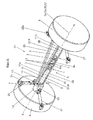
- stub axles 28 may be present ( Fig. 3-5 ).
- the stub axles 28 serve as sealing plugs.
- the stub axles 28 in each case protrude partially into the inner bore 6 and close this pressure and media tight.
- the protruding from the inner bore 6 journals of the axle stub 28 serve as a wheel bearing.
- the stub axles 28 are screwed, for example, in the inner bore 6 and thus releasably connected to the axle tube 11.
- the stub axle 28 may be welded to the axle tube 11, so be inseparably connected to this.
- filling openings 13 for filling the spaces 8a; 8b; 9a: 9b are formed in the storage housing 2 designed as axle body 5, in particular in the pipe wall 29 of the axle tube 11.
- each of the separating piston 3 seen in longitudinal section has the shape of a double-T, wherein in the circumference of the horizontal T-leg 14 grooves for receiving circumferential seals 16 are arranged and the vertical T-leg 17 forms a piston partition.
- the separating piston 3 according to the invention are dimensioned such that their piston length L, ie their extent in the direction of the housing longitudinal axis X-X, greater than / equal to the inner diameter of the circular inner bore 6 of the storage housing 2.
- the axle tube 11 is designed with respect to the wall thickness d and the manufacturing material used such that the forces occurring without affecting the free movement of the separating piston 3 and the separating piston 3 is ensured. In this case, it is furthermore necessary for the sealing function of the seals 16 to ensure effective separation of the storage spaces 8a, 9a from the pressure chambers 8b, 9b.
- the invention relates to a vehicle suspension system using a vehicle axle 31 according to the invention with at least one, preferably two, piston accumulators 1 according to the invention in such a vehicle suspension system at least one hydraulic, in particular double-acting, telescopic spring cylinder 20; 20a is present per vehicle wheel 4, which is mechanically connected at one end to the axle body 5, eg with the respective closure cap 12, and at the other end to the vehicle body or the vehicle body, see also Fig. 2 and 3 ,
- the telescopic spring cylinder 20, 20a is a hydraulic cylinder.
- Such a telescopic spring cylinder 20, 20a ( Fig.
- cylinder 3 consists of a hollow cylinder 21 and a piston 22 displaceable therein in the direction of a cylinder longitudinal axis YY of the telescopic spring cylinder 20; 20a with a piston rod 23 guided outwardly out of the hollow cylinder 21.
- the piston 22 divides within the hollow cylinder 21 Cylinder space or piston chamber 24 of the piston rod 23 enclosing annular space 25 from.
- the cylinder chamber 24 is preferably arranged above the annular space 25 and the cylinder longitudinal axis YY is preferably oriented vertically.
- Both chambers 24, 25 are filled with a hydraulic medium, wherein the hollow cylinder 21, in particular the cylinder chamber 24, via a hydraulic connection, in particular via an attenuator, in particular a damping valve having valve block 10 (Fig. Fig. 4 and 5 ), with the also filled with the hydraulic medium storage spaces 8a, 9a of the piston accumulator 1 is connected.
- the hydraulic medium within the storage spaces 8a, 9a is under a pressure p 1 or p 2 .
- the separation of each piston 3 opposing pressure chamber 8b; 9b is filled with a compressible medium which is under a pressure p 3 and p. 4
- a compressible medium advantageously a gas or nitrogen is used.
- the separating pistons 3 are respectively moved by the pressure or volume of the media in the spaces 8a; 8b: 9a; 9b until they are in a static position and a pressure equilibrium has been established.
- the interconnection of the storage spaces 8a, 9a and pressure chambers 8b, 9b and the spaces 24, 25 of the telescopic spring cylinders 20, 20a advantageously serves as a so-called cross-circuit, which is incorporated in FIGS Fig. 4 and 5 is shown.
- the cross-connection in each case the annular space 25 of a telescopic spring cylinder 20, 20a is hydraulically connected to the storage space 8a, 9a of the piston accumulator 1 which lies on the same side of the center plane 15 as the respective telescopic spring cylinder 20; 20a.
- the cylinder space 24 of the respective telescopic spring cylinder 20, 20a is hydraulically connected to the storage space 8a, 9a of the piston accumulator 1 which lies on the other side of the center plane 15 like the respective telescopic spring cylinder 20, 20a. But this can also be exactly the opposite. As a result, the driving stability is improved, in particular reduces the roll.
- the cylinder space 24 of the respective telescopic spring cylinder 20, 20a is hydraulically connected to the storage space 8a, 9a of that piston accumulator 1, which lies on the same side of the center plane 15 as the respective telescopic spring cylinder 20; 20a.
- a valve block 10 which contains the necessary damping valves.
- the telescopic spring cylinder 20; 20a are each connected via hydraulic lines 18 to the valve block 10.
- the cylinder chambers 24 are hydraulically connected to the valve block 10, wherein the valve block 10 is in turn hydraulically connected to the respective storage space 8a, 9a.
- the cylinder chambers 24 are thus each hydraulically connected via a damping means with the respective storage space 8a, 9a.
- the annular spaces 25 each directly, so not via the valve block 10, in particular without damping, with the respective storage space 8a, 9a hydraulically connected.
- valve block 10 is formed and arranged separately from the axle body 5 and also connected via hydraulic lines 18 to the respective pressure or storage spaces 8a, 9a, 8b, 9b.
- valve body 10 is preferably part of the axle body 5 (FIG. Fig. 5 ).
- the valve block 10 is arranged between the two Achsrohrabêten 11 a, 11 b and has two mutually parallel, perpendicular to the longitudinal axis 5a, block side surfaces 10a.
- the valve block 10 divides the axle tube 11 into the two axle tube sections 11a, 11b.
- the valve body 10 separates the two axle tube sections 11a, 11b from each other in terms of fluid technology. Consequently, the two inner bore sections 8, 9 are each one-end, in the region of the free axle body ends the axle body 5, through the stub axle 28 and the other end, near the center plane 15, closed by the valve body 10 media and pressure-tight.
- the axle body 5 is preferably produced from the two pipe sections 11a, 11b which are open on both sides. These are each set at one end against the block side surfaces 10a and flanged to the valve block 10 pressure and media-tight.
- the two block side surfaces 10a then delimit the two inner bore sections 8; 9.
- the valve block 10 has filling openings 19, which open at the block side surfaces 10a in the two inner bore sections 8, 9.
- the two inner bore sections 8, 9, in particular the two storage chambers 8a, 3a are hydraulically connected to the valve block 10 via the filling openings 19.
- each telescopic spring cylinder 20, 20a is present per vehicle wheel 4. It is also within the scope of the invention if, per vehicle wheel 4, several, for example two, telescopic spring cylinders 20, 20a are used. That is, on each side of the center plane 15 a plurality of telescopic spring cylinders 20, 20a are present. These are then connected in pairs to the associated memory spaces 8a, 9a and pressure chambers 8b, 9b. In particular, preferably all telescopic spring cylinders 20, 20a are cross-connected.
- a wishbone 33 ( Fig. 4 and 5 ) present, which serves in a conventional manner for absorbing shear forces and moments.
- the wishbone 33 is disposed between the two trailing arms 27.
- the wishbone 33 consists of two individual semi-trailing arms 34, which are also each mechanically connected to the axle body 5 at one end and to the vehicle body or the vehicle body at the other end.
- the wishbone 33 can also be formed in one piece (not shown).
- a coupling rod 26 (FIG. Fig. 1 and 2 ), in particular a Panhard rod, be connected to each other, which serves in a conventional manner for absorbing transverse forces.
- the coupling rod 26 is fastened at one end to the axle body 5 and at the other end to the vehicle body or the vehicle body in each case by means of rubber-metal joints.
- the present invention is characterized by a very constructively simple and space-saving design.
- the invention is not limited to the illustrated and described embodiments, but also includes all the same in the context of the invention embodiments. Furthermore, the invention has hitherto not been limited to the combination of features defined in the respective independent claim, but may also be defined by any other combination of specific features of all individually disclosed individual features. This means that in principle virtually every individual feature of the respective independent claim can be omitted or replaced by at least one individual feature disclosed elsewhere in the application. In this respect, the claims are to be understood merely as a first formulation attempt for an invention.
- the outer circumference of the axle tube 11 has a square or other cross section instead of the illustrated circular cross section.
- the piston accumulator 1 is not a hydropneumatic piston accumulator but a spring accumulator.
- a spring accumulator instead of the gas (pneumatic spring element), a mechanical spring element, e.g. a coil spring, available.
- the invention is not limited to the illustrated arrangement of the storage and pressure chambers 8a, 9a, 8b, 9b.
- the two storage spaces 8a, 9a face the center plane 15 and the two pressure chambers 8b, 9b face the free axle end 9a, 8b, 9b
- the spaces 8a, 9a, 8b, 9b can also be arranged the other way round.
- the axle body 5 preferably also has fastening means for the mechanical fastening of an air spring, in addition to the fastening means for the mechanical fastening of the telescopic spring cylinders 20, 20a, the coupling rod 26 or the oblique link 34 and the trailing arm 27.
- the vehicle axle 31 has in this case a single piston accumulator 1 according to the invention.
- a single piston accumulator 1 according to the invention.
- a vehicle, in particular a trailer or trailer has a plurality of vehicle axles 31.
- only two of the vehicle axles 31 each have a single piston accumulator 1.
- This is hydraulically connected to all telescopic spring cylinders 20, 20a on each side of the vehicle. That is, the telescopic spring cylinders 20, 20a arranged on the same side of the vehicle are hydraulically connected with each other and with one of the two piston accumulators 1. But also a cross circuit and any other interconnections are possible.
Landscapes
- Engineering & Computer Science (AREA)
- Mechanical Engineering (AREA)
- Vehicle Body Suspensions (AREA)
Priority Applications (1)
| Application Number | Priority Date | Filing Date | Title |
|---|---|---|---|
| EP14152197.1A EP2899043B1 (fr) | 2014-01-22 | 2014-01-22 | Accumulateur à piston, essieu de véhicule et système de suspension de véhicule doté d'un tel accumulateur à piston |
Applications Claiming Priority (1)
| Application Number | Priority Date | Filing Date | Title |
|---|---|---|---|
| EP14152197.1A EP2899043B1 (fr) | 2014-01-22 | 2014-01-22 | Accumulateur à piston, essieu de véhicule et système de suspension de véhicule doté d'un tel accumulateur à piston |
Publications (3)
| Publication Number | Publication Date |
|---|---|
| EP2899043A1 true EP2899043A1 (fr) | 2015-07-29 |
| EP2899043A9 EP2899043A9 (fr) | 2015-09-16 |
| EP2899043B1 EP2899043B1 (fr) | 2018-01-10 |
Family
ID=49998097
Family Applications (1)
| Application Number | Title | Priority Date | Filing Date |
|---|---|---|---|
| EP14152197.1A Not-in-force EP2899043B1 (fr) | 2014-01-22 | 2014-01-22 | Accumulateur à piston, essieu de véhicule et système de suspension de véhicule doté d'un tel accumulateur à piston |
Country Status (1)
| Country | Link |
|---|---|
| EP (1) | EP2899043B1 (fr) |
Cited By (1)
| Publication number | Priority date | Publication date | Assignee | Title |
|---|---|---|---|---|
| WO2018054739A1 (fr) * | 2016-09-21 | 2018-03-29 | Saf-Holland Gmbh | Système d'essieu |
Citations (6)
| Publication number | Priority date | Publication date | Assignee | Title |
|---|---|---|---|---|
| DE1087466B (de) * | 1957-01-04 | 1960-08-18 | Beteiligungs & Patentverw Gmbh | Hydropneumatische Federung, insbesondere fuer Kraftfahrzeuge |
| US20030132626A1 (en) * | 2002-01-11 | 2003-07-17 | Carlstedt Robert P. | Incorporation of suspension elements in vehicle frame components |
| US20040251653A1 (en) * | 2003-06-10 | 2004-12-16 | Horikiri, Inc. | Air suspension |
| EP1500531A1 (fr) * | 2003-07-22 | 2005-01-26 | KNORR-BREMSE SYSTEME FÜR NUTZFAHRZEUGE GmbH | Soupape de freinage pour une remorque ou semi-remorque à commande intégrée de la suspension pneumatique |
| DE202009018583U1 (de) | 2009-08-19 | 2012-02-28 | Hemscheidt Fahrwerktechnik Gmbh & Co. Kg | Hydropneumatischer Kolbenspeicher |
| DE102012203829A1 (de) * | 2012-03-12 | 2013-09-12 | Ford Global Technologies, Llc | Radaufhängung für ein Fahrzeug |
-
2014
- 2014-01-22 EP EP14152197.1A patent/EP2899043B1/fr not_active Not-in-force
Patent Citations (6)
| Publication number | Priority date | Publication date | Assignee | Title |
|---|---|---|---|---|
| DE1087466B (de) * | 1957-01-04 | 1960-08-18 | Beteiligungs & Patentverw Gmbh | Hydropneumatische Federung, insbesondere fuer Kraftfahrzeuge |
| US20030132626A1 (en) * | 2002-01-11 | 2003-07-17 | Carlstedt Robert P. | Incorporation of suspension elements in vehicle frame components |
| US20040251653A1 (en) * | 2003-06-10 | 2004-12-16 | Horikiri, Inc. | Air suspension |
| EP1500531A1 (fr) * | 2003-07-22 | 2005-01-26 | KNORR-BREMSE SYSTEME FÜR NUTZFAHRZEUGE GmbH | Soupape de freinage pour une remorque ou semi-remorque à commande intégrée de la suspension pneumatique |
| DE202009018583U1 (de) | 2009-08-19 | 2012-02-28 | Hemscheidt Fahrwerktechnik Gmbh & Co. Kg | Hydropneumatischer Kolbenspeicher |
| DE102012203829A1 (de) * | 2012-03-12 | 2013-09-12 | Ford Global Technologies, Llc | Radaufhängung für ein Fahrzeug |
Cited By (1)
| Publication number | Priority date | Publication date | Assignee | Title |
|---|---|---|---|---|
| WO2018054739A1 (fr) * | 2016-09-21 | 2018-03-29 | Saf-Holland Gmbh | Système d'essieu |
Also Published As
| Publication number | Publication date |
|---|---|
| EP2899043B1 (fr) | 2018-01-10 |
| EP2899043A9 (fr) | 2015-09-16 |
Similar Documents
| Publication | Publication Date | Title |
|---|---|---|
| DE69002807T2 (de) | Lenkungsdämpfer. | |
| DE855644C (de) | Stossdaempfer und gedaempfte Federung | |
| EP2671001B1 (fr) | Ensemble piston-cylindre hydropneumatique | |
| DE2938927A1 (de) | Befestigungsvorrichtung fuer teleskopstossdaempfer in aufhaengungen | |
| DE112013004595B4 (de) | Aufhängungsvorrichtung | |
| DE2624475A1 (de) | Hydraulischer stossdaempfer | |
| DE4116399A1 (de) | Kolbenzylindereinheit fuer hohe querkraefte | |
| EP0301051B1 (fr) | Suspension d'essieux pour vehicules, notamment pour vehicules lourds a deux ou plusieurs essieux | |
| EP1709334A1 (fr) | Accumulateur de pression, en particulier amortisseur de pulsations | |
| DE69909863T2 (de) | Dämpferbein mit in seinem oberen Bereich angebrachter Lenkvorrichtung | |
| DE102015218296B4 (de) | Schwingungsdämpfer | |
| EP0854815B1 (fr) | Colonne de direction pour automobile | |
| DE102011121777B4 (de) | Doppeltwirkender Hydraulikzylinder mit integrierten Kolbenspeichern | |
| DE3121630C2 (fr) | ||
| DE102010060251A1 (de) | Radaufhängung | |
| DE1296026B (de) | Doppeltwirkender hydraulischer Teleskopschwingungsdaempfer, insbesondere fuer Kraftfahrzeuge | |
| EP2249057A1 (fr) | Dispositif d'amortissement pour véhicules à roues | |
| EP2899043B1 (fr) | Accumulateur à piston, essieu de véhicule et système de suspension de véhicule doté d'un tel accumulateur à piston | |
| EP0737610A2 (fr) | Direction à crémaillère hydraulique | |
| EP1715215B1 (fr) | Amortisseur à ressort pneumatique | |
| DE102015117757B4 (de) | Lenkerende | |
| EP3329142B1 (fr) | Amortisseur de vibrations télescopique monotube hydraulique | |
| DE10047878A1 (de) | Stossdämpfer mit amplitudenabhängiger Dämpfung | |
| EP1950426A2 (fr) | Elément d'appui hydromécanique, en particulier jambe de force | |
| DE102009035570A1 (de) | Hydropneumatische Kolbenzylinderanordnung |
Legal Events
| Date | Code | Title | Description |
|---|---|---|---|
| PUAI | Public reference made under article 153(3) epc to a published international application that has entered the european phase |
Free format text: ORIGINAL CODE: 0009012 |
|
| 17P | Request for examination filed |
Effective date: 20140122 |
|
| AK | Designated contracting states |
Kind code of ref document: A1 Designated state(s): AL AT BE BG CH CY CZ DE DK EE ES FI FR GB GR HR HU IE IS IT LI LT LU LV MC MK MT NL NO PL PT RO RS SE SI SK SM TR |
|
| AX | Request for extension of the european patent |
Extension state: BA ME |
|
| RIN1 | Information on inventor provided before grant (corrected) |
Inventor name: NAPLOSZEK, HARTWIG Inventor name: WOEHRMANN, MARK, DR.-ING. |
|
| 17P | Request for examination filed |
Effective date: 20160112 |
|
| 17Q | First examination report despatched |
Effective date: 20160715 |
|
| GRAP | Despatch of communication of intention to grant a patent |
Free format text: ORIGINAL CODE: EPIDOSNIGR1 |
|
| STAA | Information on the status of an ep patent application or granted ep patent |
Free format text: STATUS: GRANT OF PATENT IS INTENDED |
|
| INTG | Intention to grant announced |
Effective date: 20170807 |
|
| GRAS | Grant fee paid |
Free format text: ORIGINAL CODE: EPIDOSNIGR3 |
|
| GRAA | (expected) grant |
Free format text: ORIGINAL CODE: 0009210 |
|
| STAA | Information on the status of an ep patent application or granted ep patent |
Free format text: STATUS: THE PATENT HAS BEEN GRANTED |
|
| AK | Designated contracting states |
Kind code of ref document: B1 Designated state(s): AL AT BE BG CH CY CZ DE DK EE ES FI FR GB GR HR HU IE IS IT LI LT LU LV MC MK MT NL NO PL PT RO RS SE SI SK SM TR |
|
| REG | Reference to a national code |
Ref country code: CH Ref legal event code: EP Ref country code: AT Ref legal event code: REF Ref document number: 961974 Country of ref document: AT Kind code of ref document: T Effective date: 20180115 |
|
| REG | Reference to a national code |
Ref country code: NL Ref legal event code: FP Ref country code: IE Ref legal event code: FG4D Free format text: LANGUAGE OF EP DOCUMENT: GERMAN |
|
| REG | Reference to a national code |
Ref country code: DE Ref legal event code: R096 Ref document number: 502014006929 Country of ref document: DE |
|
| PG25 | Lapsed in a contracting state [announced via postgrant information from national office to epo] |
Ref country code: FI Free format text: LAPSE BECAUSE OF FAILURE TO SUBMIT A TRANSLATION OF THE DESCRIPTION OR TO PAY THE FEE WITHIN THE PRESCRIBED TIME-LIMIT Effective date: 20180110 Ref country code: LT Free format text: LAPSE BECAUSE OF FAILURE TO SUBMIT A TRANSLATION OF THE DESCRIPTION OR TO PAY THE FEE WITHIN THE PRESCRIBED TIME-LIMIT Effective date: 20180110 Ref country code: CY Free format text: LAPSE BECAUSE OF FAILURE TO SUBMIT A TRANSLATION OF THE DESCRIPTION OR TO PAY THE FEE WITHIN THE PRESCRIBED TIME-LIMIT Effective date: 20180110 Ref country code: HR Free format text: LAPSE BECAUSE OF FAILURE TO SUBMIT A TRANSLATION OF THE DESCRIPTION OR TO PAY THE FEE WITHIN THE PRESCRIBED TIME-LIMIT Effective date: 20180110 Ref country code: NO Free format text: LAPSE BECAUSE OF FAILURE TO SUBMIT A TRANSLATION OF THE DESCRIPTION OR TO PAY THE FEE WITHIN THE PRESCRIBED TIME-LIMIT Effective date: 20180410 Ref country code: ES Free format text: LAPSE BECAUSE OF FAILURE TO SUBMIT A TRANSLATION OF THE DESCRIPTION OR TO PAY THE FEE WITHIN THE PRESCRIBED TIME-LIMIT Effective date: 20180110 |
|
| PG25 | Lapsed in a contracting state [announced via postgrant information from national office to epo] |
Ref country code: IS Free format text: LAPSE BECAUSE OF FAILURE TO SUBMIT A TRANSLATION OF THE DESCRIPTION OR TO PAY THE FEE WITHIN THE PRESCRIBED TIME-LIMIT Effective date: 20180510 Ref country code: BG Free format text: LAPSE BECAUSE OF FAILURE TO SUBMIT A TRANSLATION OF THE DESCRIPTION OR TO PAY THE FEE WITHIN THE PRESCRIBED TIME-LIMIT Effective date: 20180410 Ref country code: RS Free format text: LAPSE BECAUSE OF FAILURE TO SUBMIT A TRANSLATION OF THE DESCRIPTION OR TO PAY THE FEE WITHIN THE PRESCRIBED TIME-LIMIT Effective date: 20180110 Ref country code: PL Free format text: LAPSE BECAUSE OF FAILURE TO SUBMIT A TRANSLATION OF THE DESCRIPTION OR TO PAY THE FEE WITHIN THE PRESCRIBED TIME-LIMIT Effective date: 20180110 Ref country code: LV Free format text: LAPSE BECAUSE OF FAILURE TO SUBMIT A TRANSLATION OF THE DESCRIPTION OR TO PAY THE FEE WITHIN THE PRESCRIBED TIME-LIMIT Effective date: 20180110 Ref country code: SE Free format text: LAPSE BECAUSE OF FAILURE TO SUBMIT A TRANSLATION OF THE DESCRIPTION OR TO PAY THE FEE WITHIN THE PRESCRIBED TIME-LIMIT Effective date: 20180110 Ref country code: GR Free format text: LAPSE BECAUSE OF FAILURE TO SUBMIT A TRANSLATION OF THE DESCRIPTION OR TO PAY THE FEE WITHIN THE PRESCRIBED TIME-LIMIT Effective date: 20180411 |
|
| REG | Reference to a national code |
Ref country code: CH Ref legal event code: PL |
|
| PG25 | Lapsed in a contracting state [announced via postgrant information from national office to epo] |
Ref country code: MT Free format text: LAPSE BECAUSE OF FAILURE TO SUBMIT A TRANSLATION OF THE DESCRIPTION OR TO PAY THE FEE WITHIN THE PRESCRIBED TIME-LIMIT Effective date: 20180110 |
|
| REG | Reference to a national code |
Ref country code: DE Ref legal event code: R097 Ref document number: 502014006929 Country of ref document: DE |
|
| PG25 | Lapsed in a contracting state [announced via postgrant information from national office to epo] |
Ref country code: LU Free format text: LAPSE BECAUSE OF NON-PAYMENT OF DUE FEES Effective date: 20180122 Ref country code: IT Free format text: LAPSE BECAUSE OF FAILURE TO SUBMIT A TRANSLATION OF THE DESCRIPTION OR TO PAY THE FEE WITHIN THE PRESCRIBED TIME-LIMIT Effective date: 20180110 Ref country code: RO Free format text: LAPSE BECAUSE OF FAILURE TO SUBMIT A TRANSLATION OF THE DESCRIPTION OR TO PAY THE FEE WITHIN THE PRESCRIBED TIME-LIMIT Effective date: 20180110 Ref country code: EE Free format text: LAPSE BECAUSE OF FAILURE TO SUBMIT A TRANSLATION OF THE DESCRIPTION OR TO PAY THE FEE WITHIN THE PRESCRIBED TIME-LIMIT Effective date: 20180110 Ref country code: MC Free format text: LAPSE BECAUSE OF FAILURE TO SUBMIT A TRANSLATION OF THE DESCRIPTION OR TO PAY THE FEE WITHIN THE PRESCRIBED TIME-LIMIT Effective date: 20180110 Ref country code: AL Free format text: LAPSE BECAUSE OF FAILURE TO SUBMIT A TRANSLATION OF THE DESCRIPTION OR TO PAY THE FEE WITHIN THE PRESCRIBED TIME-LIMIT Effective date: 20180110 |
|
| REG | Reference to a national code |
Ref country code: IE Ref legal event code: MM4A |
|
| REG | Reference to a national code |
Ref country code: BE Ref legal event code: MM Effective date: 20180131 |
|
| PLBE | No opposition filed within time limit |
Free format text: ORIGINAL CODE: 0009261 |
|
| STAA | Information on the status of an ep patent application or granted ep patent |
Free format text: STATUS: NO OPPOSITION FILED WITHIN TIME LIMIT |
|
| PG25 | Lapsed in a contracting state [announced via postgrant information from national office to epo] |
Ref country code: LI Free format text: LAPSE BECAUSE OF NON-PAYMENT OF DUE FEES Effective date: 20180131 Ref country code: DK Free format text: LAPSE BECAUSE OF FAILURE TO SUBMIT A TRANSLATION OF THE DESCRIPTION OR TO PAY THE FEE WITHIN THE PRESCRIBED TIME-LIMIT Effective date: 20180110 Ref country code: SK Free format text: LAPSE BECAUSE OF FAILURE TO SUBMIT A TRANSLATION OF THE DESCRIPTION OR TO PAY THE FEE WITHIN THE PRESCRIBED TIME-LIMIT Effective date: 20180110 Ref country code: BE Free format text: LAPSE BECAUSE OF NON-PAYMENT OF DUE FEES Effective date: 20180131 Ref country code: CH Free format text: LAPSE BECAUSE OF NON-PAYMENT OF DUE FEES Effective date: 20180131 Ref country code: SM Free format text: LAPSE BECAUSE OF FAILURE TO SUBMIT A TRANSLATION OF THE DESCRIPTION OR TO PAY THE FEE WITHIN THE PRESCRIBED TIME-LIMIT Effective date: 20180110 Ref country code: CZ Free format text: LAPSE BECAUSE OF FAILURE TO SUBMIT A TRANSLATION OF THE DESCRIPTION OR TO PAY THE FEE WITHIN THE PRESCRIBED TIME-LIMIT Effective date: 20180110 |
|
| REG | Reference to a national code |
Ref country code: FR Ref legal event code: ST Effective date: 20181102 |
|
| 26N | No opposition filed |
Effective date: 20181011 |
|
| GBPC | Gb: european patent ceased through non-payment of renewal fee |
Effective date: 20180410 |
|
| PG25 | Lapsed in a contracting state [announced via postgrant information from national office to epo] |
Ref country code: IE Free format text: LAPSE BECAUSE OF NON-PAYMENT OF DUE FEES Effective date: 20180122 |
|
| PG25 | Lapsed in a contracting state [announced via postgrant information from national office to epo] |
Ref country code: GB Free format text: LAPSE BECAUSE OF NON-PAYMENT OF DUE FEES Effective date: 20180410 Ref country code: FR Free format text: LAPSE BECAUSE OF NON-PAYMENT OF DUE FEES Effective date: 20180312 Ref country code: SI Free format text: LAPSE BECAUSE OF FAILURE TO SUBMIT A TRANSLATION OF THE DESCRIPTION OR TO PAY THE FEE WITHIN THE PRESCRIBED TIME-LIMIT Effective date: 20180110 |
|
| REG | Reference to a national code |
Ref country code: AT Ref legal event code: MM01 Ref document number: 961974 Country of ref document: AT Kind code of ref document: T Effective date: 20190122 |
|
| PG25 | Lapsed in a contracting state [announced via postgrant information from national office to epo] |
Ref country code: TR Free format text: LAPSE BECAUSE OF FAILURE TO SUBMIT A TRANSLATION OF THE DESCRIPTION OR TO PAY THE FEE WITHIN THE PRESCRIBED TIME-LIMIT Effective date: 20180110 |
|
| PG25 | Lapsed in a contracting state [announced via postgrant information from national office to epo] |
Ref country code: AT Free format text: LAPSE BECAUSE OF NON-PAYMENT OF DUE FEES Effective date: 20190122 |
|
| PG25 | Lapsed in a contracting state [announced via postgrant information from national office to epo] |
Ref country code: PT Free format text: LAPSE BECAUSE OF FAILURE TO SUBMIT A TRANSLATION OF THE DESCRIPTION OR TO PAY THE FEE WITHIN THE PRESCRIBED TIME-LIMIT Effective date: 20180110 |
|
| PG25 | Lapsed in a contracting state [announced via postgrant information from national office to epo] |
Ref country code: HU Free format text: LAPSE BECAUSE OF FAILURE TO SUBMIT A TRANSLATION OF THE DESCRIPTION OR TO PAY THE FEE WITHIN THE PRESCRIBED TIME-LIMIT; INVALID AB INITIO Effective date: 20140122 Ref country code: MK Free format text: LAPSE BECAUSE OF NON-PAYMENT OF DUE FEES Effective date: 20180110 |
|
| PGFP | Annual fee paid to national office [announced via postgrant information from national office to epo] |
Ref country code: NL Payment date: 20210120 Year of fee payment: 8 |
|
| PGFP | Annual fee paid to national office [announced via postgrant information from national office to epo] |
Ref country code: DE Payment date: 20210120 Year of fee payment: 8 |
|
| REG | Reference to a national code |
Ref country code: DE Ref legal event code: R119 Ref document number: 502014006929 Country of ref document: DE |
|
| REG | Reference to a national code |
Ref country code: NL Ref legal event code: MM Effective date: 20220201 |
|
| PG25 | Lapsed in a contracting state [announced via postgrant information from national office to epo] |
Ref country code: NL Free format text: LAPSE BECAUSE OF NON-PAYMENT OF DUE FEES Effective date: 20220201 Ref country code: DE Free format text: LAPSE BECAUSE OF NON-PAYMENT OF DUE FEES Effective date: 20220802 |