EP2899081A2 - Système et procédé de surveillance de l'état de frein d'avion - Google Patents
Système et procédé de surveillance de l'état de frein d'avion Download PDFInfo
- Publication number
- EP2899081A2 EP2899081A2 EP14174849.1A EP14174849A EP2899081A2 EP 2899081 A2 EP2899081 A2 EP 2899081A2 EP 14174849 A EP14174849 A EP 14174849A EP 2899081 A2 EP2899081 A2 EP 2899081A2
- Authority
- EP
- European Patent Office
- Prior art keywords
- friction material
- processor
- implemented
- runway
- model
- Prior art date
- Legal status (The legal status is an assumption and is not a legal conclusion. Google has not performed a legal analysis and makes no representation as to the accuracy of the status listed.)
- Granted
Links
Images

Classifications
-
- B—PERFORMING OPERATIONS; TRANSPORTING
- B60—VEHICLES IN GENERAL
- B60T—VEHICLE BRAKE CONTROL SYSTEMS OR PARTS THEREOF; BRAKE CONTROL SYSTEMS OR PARTS THEREOF, IN GENERAL; ARRANGEMENT OF BRAKING ELEMENTS ON VEHICLES IN GENERAL; PORTABLE DEVICES FOR PREVENTING UNWANTED MOVEMENT OF VEHICLES; VEHICLE MODIFICATIONS TO FACILITATE COOLING OF BRAKES
- B60T17/00—Component parts, details, or accessories of power brake systems not covered by groups B60T8/00, B60T13/00 or B60T15/00, or presenting other characteristic features
- B60T17/18—Safety devices; Monitoring
- B60T17/22—Devices for monitoring or checking brake systems; Signal devices
- B60T17/221—Procedure or apparatus for checking or keeping in a correct functioning condition of brake systems
-
- B—PERFORMING OPERATIONS; TRANSPORTING
- B60—VEHICLES IN GENERAL
- B60T—VEHICLE BRAKE CONTROL SYSTEMS OR PARTS THEREOF; BRAKE CONTROL SYSTEMS OR PARTS THEREOF, IN GENERAL; ARRANGEMENT OF BRAKING ELEMENTS ON VEHICLES IN GENERAL; PORTABLE DEVICES FOR PREVENTING UNWANTED MOVEMENT OF VEHICLES; VEHICLE MODIFICATIONS TO FACILITATE COOLING OF BRAKES
- B60T8/00—Arrangements for adjusting wheel-braking force to meet varying vehicular or ground-surface conditions, e.g. limiting or varying distribution of braking force
- B60T8/32—Arrangements for adjusting wheel-braking force to meet varying vehicular or ground-surface conditions, e.g. limiting or varying distribution of braking force responsive to a speed condition, e.g. acceleration or deceleration
- B60T8/88—Arrangements for adjusting wheel-braking force to meet varying vehicular or ground-surface conditions, e.g. limiting or varying distribution of braking force responsive to a speed condition, e.g. acceleration or deceleration with failure responsive means, i.e. means for detecting and indicating faulty operation of the speed responsive control means
- B60T8/885—Arrangements for adjusting wheel-braking force to meet varying vehicular or ground-surface conditions, e.g. limiting or varying distribution of braking force responsive to a speed condition, e.g. acceleration or deceleration with failure responsive means, i.e. means for detecting and indicating faulty operation of the speed responsive control means using electrical circuitry
-
- B—PERFORMING OPERATIONS; TRANSPORTING
- B64—AIRCRAFT; AVIATION; COSMONAUTICS
- B64C—AEROPLANES; HELICOPTERS
- B64C25/00—Alighting gear
- B64C25/32—Alighting gear characterised by elements which contact the ground or similar surface
- B64C25/42—Arrangement or adaptation of brakes
-
- F—MECHANICAL ENGINEERING; LIGHTING; HEATING; WEAPONS; BLASTING
- F16—ENGINEERING ELEMENTS AND UNITS; GENERAL MEASURES FOR PRODUCING AND MAINTAINING EFFECTIVE FUNCTIONING OF MACHINES OR INSTALLATIONS; THERMAL INSULATION IN GENERAL
- F16D—COUPLINGS FOR TRANSMITTING ROTATION; CLUTCHES; BRAKES
- F16D55/00—Brakes with substantially-radial braking surfaces pressed together in axial direction, e.g. disc brakes
- F16D55/24—Brakes with substantially-radial braking surfaces pressed together in axial direction, e.g. disc brakes with a plurality of axially-movable discs, lamellae, or pads, pressed from one side towards an axially-located member
- F16D55/26—Brakes with substantially-radial braking surfaces pressed together in axial direction, e.g. disc brakes with a plurality of axially-movable discs, lamellae, or pads, pressed from one side towards an axially-located member without self-tightening action
- F16D55/36—Brakes with a plurality of rotating discs all lying side by side
-
- B—PERFORMING OPERATIONS; TRANSPORTING
- B60—VEHICLES IN GENERAL
- B60T—VEHICLE BRAKE CONTROL SYSTEMS OR PARTS THEREOF; BRAKE CONTROL SYSTEMS OR PARTS THEREOF, IN GENERAL; ARRANGEMENT OF BRAKING ELEMENTS ON VEHICLES IN GENERAL; PORTABLE DEVICES FOR PREVENTING UNWANTED MOVEMENT OF VEHICLES; VEHICLE MODIFICATIONS TO FACILITATE COOLING OF BRAKES
- B60T2270/00—Further aspects of brake control systems not otherwise provided for
- B60T2270/40—Failsafe aspects of brake control systems
- B60T2270/406—Test-mode; Self-diagnosis
Definitions
- the present invention generally relates to aircraft brakes, and more particularly relates to an aircraft brake health monitoring system and method.
- the aircraft brakes When a jet-powered aircraft lands, the aircraft brakes, various aerodynamic drag sources (e.g., flaps, spoilers, etc.), and, in many instances, aircraft thrust reversers, are used to slow the aircraft down in the desired amount of runway distance. When the aircraft is sufficiently slowed, and is taxiing from the runway toward its ground destination, the aircraft brakes are used to slow the aircraft, and bring it to a stop at its final ground destination.
- various aerodynamic drag sources e.g., flaps, spoilers, etc.
- aircraft thrust reversers are used to slow the aircraft down in the desired amount of runway distance.
- many aircraft brake systems include a plurality of hydraulic or electromechanical actuators, and a plurality of wheel mounted brakes.
- the brakes in many aircraft are implemented as multi-disk brakes, which include a plurality of stator disks and rotor disks.
- the stator disks and rotor disks may be alternately splined to a torque tube or wheel rim, and disposed parallel to one another, to form a brake stack.
- the actuators in response to an appropriate pilot-initiated command, move between an engage position and a disengage position. In the engage position, the actuators each engage a brake stack, moving the brake disks into engagement with one another, to thereby generate the desired braking force.
- the disks that comprise a brake stack are formed of a carbon or carbon composite material. Because the brakes rely on friction to slow or stop the aircraft, the disks are subject to wear. As such, the brakes undergo routine visual inspections to determine the amount of wear of the friction material. At times, these routine inspections detect unanticipated amounts of wear, which can cause unanticipated dispatch delays and/or aircraft downtime. Both of these unanticipated events can be costly to an operator.
- a method of estimating health of aircraft brake system friction material includes sensing a temperature of the friction material, and supplying the sensed temperature to a processor-implemented thermal model that is configured to estimate friction material temperatures at one or more locations on the friction material.
- the estimates of friction material temperatures are supplied to a processor-implemented thermal oxidation model that is configured, based on the estimates of friction material temperatures, to estimate friction material loss due to thermal oxidation.
- Data representative of runway fluid exposure are supplied to a processor-implemented catalytic oxidation model that is configured, based on the runway fluid exposure, to estimate friction material loss due to catalytic oxidation.
- the health of the friction material is estimated based on the estimates of friction material loss from the processor-implemented thermal oxidation model and the processor-implemented catalytic oxidation model.
- a system for estimating remaining useful life of brake system friction material includes a temperature sensor, a runway fluid data source, and a processor.
- the temperature sensor is configured to sense a temperature that is at least representative of the friction material and supply a friction material temperature signal.
- the runway fluid data source configured to at least selectively supply data representative of runway fluid exposure.
- the processor coupled to receive the friction material temperature signal and the data representative of runway fluid exposure and is configured, upon receipt thereof, to estimate friction material temperatures at one or more locations on the friction material, estimate friction material loss due to thermal oxidation based on the estimates of friction material temperatures, estimate friction material loss due to catalytic oxidation based on the runway fluid exposure, and estimate the remaining useful life of the friction material based on the estimates of friction material loss.
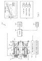
- FIG. 1 a functional block diagram of an aircraft brake health monitoring system 100 is depicted, and includes an aircraft brake 102, a temperature sensor 104, a runway fluid data source 106, a landing conditions data source 108, and a processor 110.
- the system 100 may be, and indeed likely would be, implemented on aircraft that include more than one aircraft brake 102. For convenience and ease of both illustration and description, only a single aircraft brake 102 is depicted.
- the aircraft brake 102 may be variously configured and implemented, but in the depicted embodiment an aircraft wheel 112 is mounted over the aircraft brake 102, which includes an actuator 114, a brake stack 116, and an axle 118.
- the wheel 112 includes an inboard wheel half 120 and an outboard wheel half 122.
- the outboard wheel half 122 is coupled to the inboard wheel half 120 via lug bolts 126 and lug nuts 128.
- an inflatable tire (not shown) may be mounted on the wheel 112. Thereafter, the lug nuts 128 can be tightened on the lug bolts 126, and the inflatable tire can be inflated.
- the actuator 114 is coupled to a torque tube 124 via, for example, actuator bolts 132.
- the actuator 114 is configured to selectively engage and disengage the brake stack 116, which includes alternating rotor disks 136 and stator disks 138.
- the rotor disks 136 are engaged by the inboard wheel half 120 via, for example, rotor drive keys 140, and the stator discs 138 are engaged by the torque tube 124 via, for example, splines 144.
- the rotor disks 136 and stator disks 138 provide opposing friction surfaces for braking an aircraft.
- the rotor disks 136 and stator disks 138 that comprise the brake stack 116 are preferably formed of robust, thermally stable friction materials capable of operating at relatively high temperatures.
- suitable friction materials include various metal alloys, such as, for example, a super alloy based on nickel (Ni), cobalt (Co), iron (Fe), or the like.
- suitable friction materials include various carbon-carbon (C--C) composite materials.
- the temperature sensor 104 is installed adjacent the brake stack 116, and is configured to sense a temperature that is at least representative of the friction material.
- the temperature sensor 104 may be implemented using any one of numerous known temperature sensors including, for example, a resistance temperature detector (RTD), a thermocouple, an optical temperature sensor, or a solid-state temperature sensor, just to name a few.
- RTD resistance temperature detector
- each aircraft brake 102 may be implemented with more than one temperature sensor 104.
- each temperature sensor 104 is configured to supply a brake temperature signal representative of the sensed temperature to the processor 110.
- each temperature sensor 104 be implemented as part of a brake temperature monitoring system (BTMS) that may be installed on the aircraft.
- BTMS brake temperature monitoring system
- the runway fluid data source 106 is in communication with the processor 110, and is configured to supply data representative of runway fluid exposure to the processor 110, such as, for example chemical properties of commonly used runway fluids.
- the runway fluid data source 106 may be variously configured and implemented.
- the runway fluid data source 106 may be a data storage device that has the data representative of runway fluid exposure stored thereon.
- the runway fluid data source 106 may be a user interface via which a user inputs the data representative of runway fluid exposure directly to the processor 110.
- the runway fluid data source 106 may be configured to determine the likelihood that a runway fluid may be present based, for example, on ambient conditions and airport location, and supply appropriate runway fluid data, if necessary, based on the determined likelihood.
- the data representative of runway fluid includes data representative of the chemical composition of runway fluid, and data representative of the exposure time of the aircraft to the runway fluid.
- the landing conditions data source 108 is in communication with, and is configured to supply data representative of aircraft landing conditions to, the processor 110.
- the landing conditions data source 108 may be variously configured and implemented.
- the landing conditions data source 108 may be a data storage device that has the data representative of aircraft landing conditions stored thereon.
- the landing conditions data source 108 may alternatively be a user interface via which a user inputs the data representative of aircraft landing conditions directly to the processor 110.
- the landing conditions data source 108 is implemented using an on-board aircraft condition monitoring system (ACMS).
- ACMS on-board aircraft condition monitoring system
- the data representative of aircraft landing conditions includes, for example, aircraft landing energy, the number of taxi stops, the ambient temperature while landing, brake pressure and, in some embodiments, aircraft velocity.
- the processor 110 is configured to implement a process for estimating the health of aircraft brake system friction material based, in part, on estimates of friction material loss.
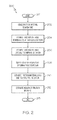
- the general process that the processor 110 implements is depicted in flowchart form in FIG. 2 , and will be briefly described.
- the process 200 is implemented (201) at commencement of each landing sequence.
- friction material temperatures are sensed (202), via the temperature sensor 104, and supplied to a processor-implemented thermal model.
- the processor-implemented thermal model estimates friction material temperatures at one or more locations on the friction material (204).
- the estimates of friction material temperatures are supplied to a processor-implemented thermal oxidation model and, based on the estimates of friction material temperatures, the thermal oxidation model estimates friction material loss due to thermal oxidation (206).
- FIG. 2 further depicts, data representative of runway fluid exposure is supplied to a processor-implemented catalytic oxidation model (208).
- the processor-implemented catalytic oxidation model based on the runway fluid exposure, estimates friction material loss due to catalytic oxidation (210). The health of the friction material is then estimated based on the estimates of friction material loss (212).
- the processor 110 may also be configured, as will be described further below, to estimate friction material loss due to normal wear, and to also estimate landing (and take-off) energy. It is additionally noted that the process depicted in FIG. 2 and described above is associated with a single aircraft brake 102, but that the processor 110 is preferably configured to implement a "multivariate" approach. That is, the processor 110 preferably implements the process 200 for all of the brakes on the aircraft, and not just one brake at a time. Moreover, the processor 100 is further configured to use data from a series of landings, not just a single landing, since an aircraft makes a series of landing over time. The processor 110 makes use of the "multiplicity" of brakes and "repetitive samples over several landings" to generate the estimates of health that are discussed further below.
- the processor 110 is coupled to receive the brake temperature signal, the data representative of runway fluid exposure, and the data representative of aircraft landing conditions.
- the processor 110 is configured, upon receipt of the brake temperature signal and these data, to estimate friction material loss and, based on the estimated friction material loss, to estimate the health of the friction material and thus the aircraft brake 102.
- the processor 110 is configured to implement various models. With reference to FIG. 3 , these models will now be described.
- the models implemented in the processor 110 include a wear model 302, a thermal model 304, a thermal oxidation model 306, and a catalytic oxidation model 308.
- the wear model 302 is used to determine the friction material weight loss due to normal wear.
- the wear model 302, an embodiment of which will now be described, implements a numerical integration method to determine the friction material weight loss.
- the primary function of the aircraft brakes 122 is to slow-down or stop the aircraft. During these operations the friction material wears. The rate at which the friction material wears depends on the number of stops and slow-downs that occur while the aircraft is taxing on the ground. As is generally known, taxiing occurs both after a touchdown and before a takeoff.
- the rolling radians ( ⁇ ) correspond to the distance travelled by the aircraft while the brakes are partially applied.
- D R the distance the aircraft rolls
- the summation signs (E) indicate that there could be multiple stops while taxiing.
- the number of aircraft stops during both a landing sequence and a takeoff sequence is an integer number greater than or equal to zero. This number is calculated using parameters supplied from one or more aircraft systems, such as the aforementioned ACMS, and may be determined by estimating aircraft linear velocity (v).
- v aircraft linear velocity
- the aircraft is defined as being stopped when v ⁇ 2.25 m/s for 20 seconds, and is assumed to be moving when v > 6.25 m/s. These are merely exemplary values and may be varied, if needed or desired.
- v aircraft velocity
- the landing conditions data source 108 e.g., ACMS
- GPS global positioning system
- aircraft position given as a latitude/longitude pair.
- the thermal model 304 is supplied with the brake temperature signal and is configured to estimate the friction material temperatures at one or more locations on the friction material.
- nodal locations for which temperatures are determined using this model may vary. Some example nodal locations include lug temperatures, axle temperatures, frame structure temperatures, and brake fluid temperatures, just to name a few. No matter the specific nodal locations that are used, the output from the thermal model 304 is typically values of temperature-versus-time at the nodal location(s).
- the nodal temperature-versus-time values are functions of several parameters, some of which are unknown. For example, values of T amb , FA cr , FA ax , L S , AC LW , W hs need to be either estimated or provided.
- An approach for calculating the number of taxi stops L S , T S was previously described. In the following paragraphs, an algorithm for calculating the remaining parameters, and hence determining the "right" temperature-versus-time profile to select for estimating ⁇ W to ( n ) will be described.
- the thermal oxidation model 306 receives at least some of the friction material temperature estimates supplied by the thermal model 304 and is configured to estimate the friction material loss due to thermal oxidation.
- this model 308 uses experimentally determined data for bare carbon friction material and friction material coated with, for example, an antioxidant (AO) coating. Using these experimental data, the catalytic oxidation model 308 receives the data representative of runway fluid exposure and is configured to estimate friction material loss due to catalytic oxidation ( ⁇ W co ).
- AO antioxidant
- AO coatings inhibit oxidation, but do not prevent it altogether.
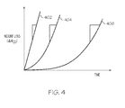
- FIG. 4 a schematic weight loss isotherm is depicted. As this shows, the oxidation of a carbon brake disk (e.g. friction material) vs. time follows a parabolic rate law. That is, at short times, there is little weight change, but with increasing time, weight loss rate increases. Without AO, as curve 402 depicts, this is a very steep parabola. As curves 404 and 406 show, the AO coating significantly widens the parabola relative to bare carbon. However, given sufficient time, the AO will be undermined by oxidation, thereby exposing unprotected carbon.
- a carbon brake disk e.g. friction material
- the slope of the parabola will become increasingly more parallel to that of the bare carbon.
- a catalyst such as a runway fluid (e.g., a deicer)
- the parabola further narrows, leading to earlier onset of high oxidation rates.
- the catalytic oxidation model 308 utilizes a generally well-known methodology for characterizing the time and temperature effect on a reaction rate. Specifically, a TGA is used to determine the weight loss of carbon materials in the catalyzed and non-catalyzed conditions as functions of time and temperature. Three or more temperatures are investigated, and a rate constant is then calculated for the oxidation reactions at each temperature. Finally, these rate constants are curve fit vs. temperature using the Arrhenius equation. The resulting models then describe the time and temperature behavior of the oxidizing carbon, and thus the weight loss thereof.
- condition indicators are: (1) the landing energy (in MJ) absorbed by the brake assembly 100 ( E ( n )); (2) friction material weight loss (in pounds) due to normal usage of the brakes ( ⁇ W wr ( n )); (3) friction material weight loss (in pounds) due to thermal oxidation ( ⁇ W t0 ( n )); and (4) friction material weight loss in pounds due to catalytic oxidation ( ⁇ W ca ( n) ).
- condition indicator is a 4-dimension state variable that may be expressed in vector notation as:
- the processor 110 will generate 4 x N values using the data available after every landing.
- the 4-dimensional state variable is updated periodically whenever a new temperature is available from the sensor 104 and a landing report is available from the landing conditions data source 108.
- the CI ( n ) values will be updated (or reset to initial values).
- a condition indicator can be trended and used as a visual indicator for subject matter expert-in-the loop decision making.
- appropriate threshold values are supplied, and corresponding health indicators ( HI ( n )) are generated and displayed based on these condition indicators ( CI ( n )).
- the processor 110 may be additionally configured to command a display device 150 to display the condition and health indicators.
- the manner in which the condition and health indicators are display may vary.
- the condition and health indicators may be displayed as depicted in FIG. 1 .
- the condition indicators may be displayed as data points plotted over time along with trend-line plot (e.g. running average).
- the trend-line plot may include graphics illustrating transitions between red-yellow-green health indicators for that condition indicator.
- the condition indicators may be displayed numerically with the latest value displayed along with an indication of its corresponding health indicator (e.g. the number is displayed green-yellow-red as appropriate).
- condition and health indicators may be performed by the processor 110, in real-time, on board the aircraft, and then downloaded from the aircraft.
- the raw data may be downloaded (via either a wired or wireless connection) from the aircraft and to a ground system 160 (see FIG. 1 ), which is configured to compute the condition and health indicators.
- the condition and health indicators are preferably stored, for example, on a central server.
- end-users may access condition and health indicator information via, for example, a suitable web interface.
- the web interface is preferably configured to provide brake condition information for all assets for which that end-user has been granted access.
- the end-user may navigate to a particular asset through a folder-tree or using a search box.
- the user may have access to a high-level summary view of all assets simultaneously.
- a page may display the individual health indicators as colors for each asset, providing a quick visual inspection to single out potential problems.
- the high-level view may include filters to focus on, for example, a single aircraft type, brake location, flight region, red health indicators, etc.
- Skilled artisans may implement the described functionality in varying ways for each particular application, but such implementation decisions should not be interpreted as causing a departure from the scope of the present invention.
- an embodiment of a system or a component may employ various integrated circuit components, e.g., memory elements, digital signal processing elements, logic elements, look-up tables, or the like, which may carry out a variety of functions under the control of one or more microprocessors or other control devices.
- integrated circuit components e.g., memory elements, digital signal processing elements, logic elements, look-up tables, or the like, which may carry out a variety of functions under the control of one or more microprocessors or other control devices.
- DSP digital signal processor
- ASIC application specific integrated circuit
- FPGA field programmable gate array
- a general-purpose processor may be a microprocessor, but in the alternative, the processor may be any conventional processor, controller, microcontroller, or state machine.
- a processor may also be implemented as a combination of computing devices, e.g., a combination of a DSP and a microprocessor, a plurality of microprocessors, one or more microprocessors in conjunction with a DSP core, or any other such configuration.
- a software module may reside in RAM memory, flash memory, ROM memory, EPROM memory, EEPROM memory, registers, hard disk, a removable disk, a CD-ROM, or any other form of storage medium known in the art.
- An exemplary storage medium is coupled to the processor such that the processor can read information from, and write information to, the storage medium.
- the storage medium may be integral to the processor.
- the processor and the storage medium may reside in an ASIC.
- the ASIC may reside in a user terminal.
- the processor and the storage medium may reside as discrete components in a user terminal.
Landscapes
- Engineering & Computer Science (AREA)
- Mechanical Engineering (AREA)
- Transportation (AREA)
- General Engineering & Computer Science (AREA)
- Aviation & Aerospace Engineering (AREA)
- Braking Arrangements (AREA)
- Valves And Accessory Devices For Braking Systems (AREA)
Applications Claiming Priority (1)
| Application Number | Priority Date | Filing Date | Title |
|---|---|---|---|
| US13/943,360 US9242628B2 (en) | 2013-07-16 | 2013-07-16 | Aircraft brake health monitoring system and method |
Publications (3)
| Publication Number | Publication Date |
|---|---|
| EP2899081A2 true EP2899081A2 (fr) | 2015-07-29 |
| EP2899081A3 EP2899081A3 (fr) | 2016-04-20 |
| EP2899081B1 EP2899081B1 (fr) | 2016-11-23 |
Family
ID=51167620
Family Applications (1)
| Application Number | Title | Priority Date | Filing Date |
|---|---|---|---|
| EP14174849.1A Active EP2899081B1 (fr) | 2013-07-16 | 2014-06-27 | Système et procédé de surveillance de l'état de frein d'avion |
Country Status (2)
| Country | Link |
|---|---|
| US (1) | US9242628B2 (fr) |
| EP (1) | EP2899081B1 (fr) |
Cited By (2)
| Publication number | Priority date | Publication date | Assignee | Title |
|---|---|---|---|---|
| EP3597496A1 (fr) * | 2018-07-16 | 2020-01-22 | Safran Landing Systems UK Limited | Ensemble de train d'atterrissage d'aeronef |
| DE102019114543B4 (de) * | 2018-09-28 | 2025-07-31 | GM Global Technology Operations LLC | Verfahren zum Ermitteln einer Restlebensdauer einer Bremskomponente |
Families Citing this family (11)
| Publication number | Priority date | Publication date | Assignee | Title |
|---|---|---|---|---|
| US9786042B2 (en) * | 2015-01-29 | 2017-10-10 | Honeywell International Inc. | Algorithm for measuring wear pin length using an input image |
| EP3359433B1 (fr) | 2015-10-07 | 2021-08-18 | Meggitt Aircraft Braking Systems Corporation | Diagnostic et pronostic de condition de frein d'aéronef |
| GB2557195A (en) * | 2016-11-30 | 2018-06-20 | Jaguar Land Rover Ltd | Controller for a braking system of a vehicle |
| GB2559329A (en) * | 2017-01-26 | 2018-08-08 | Airbus Operations Ltd | Fault detection based on brake torque and temperature |
| GB2571359A (en) * | 2018-02-27 | 2019-08-28 | Airbus Operations Ltd | Brake monitoring |
| DE102018209580A1 (de) | 2018-06-14 | 2019-12-19 | Bayerische Motoren Werke Aktiengesellschaft | Verfahren zum Ermitteln des Verschleißes eines Bremsbelages eines Fahrzeugs |
| EP3862737B1 (fr) * | 2020-02-05 | 2026-04-08 | Goodrich Corporation | Estimation de la température de frein d'avion à base de modèle |
| CN111874262A (zh) * | 2020-07-08 | 2020-11-03 | 西安航空制动科技有限公司 | 一种飞机机轮刹车盘磨损检测系统 |
| RU2761124C1 (ru) * | 2021-02-09 | 2021-12-06 | Федеральное государственное казенное военное образовательное учреждение высшего образования "Военный учебно-научный центр Военно-воздушных сил "Военно-воздушная академия имени профессора Н.Е. Жуковского и Ю.А. Гагарина" (г. Воронеж) Министерства обороны Российской Федерации | Способ определения остаточного ресурса тормозных устройств летательных аппаратов |
| CN114838071B (zh) * | 2022-04-26 | 2024-05-03 | 浙江成峰实业有限公司 | 一种刹车片磨损在线监测及刹车片寿命估算方法 |
| US12442424B2 (en) * | 2022-11-16 | 2025-10-14 | Bendix Commercial Vehicle Systems Llc | Apparatus for processing a plurality of brake wear signals from a corresponding plurality of brake wear sensors of a vehicle brake system and method therefor |
Family Cites Families (7)
| Publication number | Priority date | Publication date | Assignee | Title |
|---|---|---|---|---|
| US5596513A (en) | 1995-01-05 | 1997-01-21 | Caterpillar Inc. | Method and apparatus for estimating internal brake energy |
| EP1970274B1 (fr) * | 2000-08-04 | 2014-01-08 | Meggitt Aerospace Limited | Surveillance de l'état des freins |
| US6659233B2 (en) | 2001-12-04 | 2003-12-09 | Hydro-Aire, Inc. | System and method for aircraft braking system usage monitoring |
| DE10208961B4 (de) * | 2002-02-28 | 2006-12-28 | Audi Ag | Verschleißerkennung bei Kraftfahrzeugen |
| US7877216B2 (en) * | 2008-07-30 | 2011-01-25 | Honeywell International Inc. | Method, system, and apparatus for friction pad wear and brake condition monitoring |
| US8634971B2 (en) * | 2009-05-05 | 2014-01-21 | Goodrich Corporation | Brake wear control system |
| US8773289B2 (en) * | 2010-03-24 | 2014-07-08 | The Boeing Company | Runway condition monitoring |
-
2013
- 2013-07-16 US US13/943,360 patent/US9242628B2/en active Active
-
2014
- 2014-06-27 EP EP14174849.1A patent/EP2899081B1/fr active Active
Non-Patent Citations (1)
| Title |
|---|
| None |
Cited By (3)
| Publication number | Priority date | Publication date | Assignee | Title |
|---|---|---|---|---|
| EP3597496A1 (fr) * | 2018-07-16 | 2020-01-22 | Safran Landing Systems UK Limited | Ensemble de train d'atterrissage d'aeronef |
| US11235867B2 (en) | 2018-07-16 | 2022-02-01 | Safran Landing Systems Uk Ltd | Aircraft landing gear assembly |
| DE102019114543B4 (de) * | 2018-09-28 | 2025-07-31 | GM Global Technology Operations LLC | Verfahren zum Ermitteln einer Restlebensdauer einer Bremskomponente |
Also Published As
| Publication number | Publication date |
|---|---|
| US9242628B2 (en) | 2016-01-26 |
| EP2899081A3 (fr) | 2016-04-20 |
| EP2899081B1 (fr) | 2016-11-23 |
| US20150025735A1 (en) | 2015-01-22 |
Similar Documents
| Publication | Publication Date | Title |
|---|---|---|
| EP2899081B1 (fr) | Système et procédé de surveillance de l'état de frein d'avion | |
| EP3530532B1 (fr) | Commande de frein | |
| US10696382B2 (en) | Fault detection based on brake torque and temperature | |
| US11136145B2 (en) | Brake temperature prediction and cooling time functionality | |
| EP1970274B1 (fr) | Surveillance de l'état des freins | |
| US8151944B2 (en) | Algorithm to determine wheel and brake cooling | |
| US10005566B2 (en) | Systems and methods for detection of dragging brake | |
| US11364884B2 (en) | Selective braking of carbon brakes to improve life | |
| EP3359433B1 (fr) | Diagnostic et pronostic de condition de frein d'aéronef | |
| EP2876012B1 (fr) | Procédés pour surveiller des composants de système d'atterrissage d'un avion | |
| US11623621B2 (en) | Brake characteristics | |
| EP2684752A1 (fr) | Systèmes et procédé de détection du glissement d'une roue freinée | |
| AU2001278582A1 (en) | Brake condition monitoring | |
| EP2468596B1 (fr) | Procédé pour surveiller la performance de freinage d'un avion et appareil pour réaliser ledit procédé | |
| US20150286215A1 (en) | Methods and apparatus to predict landing system operating parameters | |
| CN113631399A (zh) | 轮胎监测 | |
| EP3862238A1 (fr) | Procédés directs et indirects pour l'estimation de l'usure des freins d'avion | |
| EP2060456B1 (fr) | Algorithme pour déterminer le refroidissement de roue et de frein | |
| Wang et al. | Evaluation of aircraft braking performance based on operational flight data |
Legal Events
| Date | Code | Title | Description |
|---|---|---|---|
| PUAI | Public reference made under article 153(3) epc to a published international application that has entered the european phase |
Free format text: ORIGINAL CODE: 0009012 |
|
| 17P | Request for examination filed |
Effective date: 20140627 |
|
| AK | Designated contracting states |
Kind code of ref document: A2 Designated state(s): AL AT BE BG CH CY CZ DE DK EE ES FI FR GB GR HR HU IE IS IT LI LT LU LV MC MK MT NL NO PL PT RO RS SE SI SK SM TR |
|
| AX | Request for extension of the european patent |
Extension state: BA ME |
|
| RAP1 | Party data changed (applicant data changed or rights of an application transferred) |
Owner name: HONEYWELL INTERNATIONAL INC. |
|
| PUAL | Search report despatched |
Free format text: ORIGINAL CODE: 0009013 |
|
| AK | Designated contracting states |
Kind code of ref document: A3 Designated state(s): AL AT BE BG CH CY CZ DE DK EE ES FI FR GB GR HR HU IE IS IT LI LT LU LV MC MK MT NL NO PL PT RO RS SE SI SK SM TR |
|
| AX | Request for extension of the european patent |
Extension state: BA ME |
|
| RIC1 | Information provided on ipc code assigned before grant |
Ipc: B64C 25/42 20060101ALI20160316BHEP Ipc: B60T 8/88 20060101ALI20160316BHEP Ipc: B60T 17/22 20060101AFI20160316BHEP Ipc: F16D 55/36 20060101ALI20160316BHEP |
|
| GRAP | Despatch of communication of intention to grant a patent |
Free format text: ORIGINAL CODE: EPIDOSNIGR1 |
|
| INTG | Intention to grant announced |
Effective date: 20160712 |
|
| RIN1 | Information on inventor provided before grant (corrected) |
Inventor name: NWADIOGBU, EMMANUEL OBIESIE Inventor name: RATEICK, JR., RICHARD Inventor name: MYLARASWAMY, DINKAR Inventor name: BEHNKE, MARK E. Inventor name: BROWN, MATTHEW Inventor name: HORBAN, GILES Inventor name: VECHART, ANDREW PETER |
|
| GRAS | Grant fee paid |
Free format text: ORIGINAL CODE: EPIDOSNIGR3 |
|
| GRAA | (expected) grant |
Free format text: ORIGINAL CODE: 0009210 |
|
| AK | Designated contracting states |
Kind code of ref document: B1 Designated state(s): AL AT BE BG CH CY CZ DE DK EE ES FI FR GB GR HR HU IE IS IT LI LT LU LV MC MK MT NL NO PL PT RO RS SE SI SK SM TR |
|
| REG | Reference to a national code |
Ref country code: GB Ref legal event code: FG4D |
|
| REG | Reference to a national code |
Ref country code: CH Ref legal event code: EP |
|
| REG | Reference to a national code |
Ref country code: IE Ref legal event code: FG4D |
|
| REG | Reference to a national code |
Ref country code: AT Ref legal event code: REF Ref document number: 847561 Country of ref document: AT Kind code of ref document: T Effective date: 20161215 |
|
| REG | Reference to a national code |
Ref country code: DE Ref legal event code: R096 Ref document number: 602014005001 Country of ref document: DE |
|
| PG25 | Lapsed in a contracting state [announced via postgrant information from national office to epo] |
Ref country code: LV Free format text: LAPSE BECAUSE OF FAILURE TO SUBMIT A TRANSLATION OF THE DESCRIPTION OR TO PAY THE FEE WITHIN THE PRESCRIBED TIME-LIMIT Effective date: 20161123 |
|
| REG | Reference to a national code |
Ref country code: LT Ref legal event code: MG4D |
|
| REG | Reference to a national code |
Ref country code: NL Ref legal event code: MP Effective date: 20161123 |
|
| REG | Reference to a national code |
Ref country code: AT Ref legal event code: MK05 Ref document number: 847561 Country of ref document: AT Kind code of ref document: T Effective date: 20161123 |
|
| PG25 | Lapsed in a contracting state [announced via postgrant information from national office to epo] |
Ref country code: GR Free format text: LAPSE BECAUSE OF FAILURE TO SUBMIT A TRANSLATION OF THE DESCRIPTION OR TO PAY THE FEE WITHIN THE PRESCRIBED TIME-LIMIT Effective date: 20170224 Ref country code: SE Free format text: LAPSE BECAUSE OF FAILURE TO SUBMIT A TRANSLATION OF THE DESCRIPTION OR TO PAY THE FEE WITHIN THE PRESCRIBED TIME-LIMIT Effective date: 20161123 Ref country code: NO Free format text: LAPSE BECAUSE OF FAILURE TO SUBMIT A TRANSLATION OF THE DESCRIPTION OR TO PAY THE FEE WITHIN THE PRESCRIBED TIME-LIMIT Effective date: 20170223 Ref country code: LT Free format text: LAPSE BECAUSE OF FAILURE TO SUBMIT A TRANSLATION OF THE DESCRIPTION OR TO PAY THE FEE WITHIN THE PRESCRIBED TIME-LIMIT Effective date: 20161123 Ref country code: NL Free format text: LAPSE BECAUSE OF FAILURE TO SUBMIT A TRANSLATION OF THE DESCRIPTION OR TO PAY THE FEE WITHIN THE PRESCRIBED TIME-LIMIT Effective date: 20161123 |
|
| REG | Reference to a national code |
Ref country code: FR Ref legal event code: PLFP Year of fee payment: 4 |
|
| PG25 | Lapsed in a contracting state [announced via postgrant information from national office to epo] |
Ref country code: AT Free format text: LAPSE BECAUSE OF FAILURE TO SUBMIT A TRANSLATION OF THE DESCRIPTION OR TO PAY THE FEE WITHIN THE PRESCRIBED TIME-LIMIT Effective date: 20161123 Ref country code: ES Free format text: LAPSE BECAUSE OF FAILURE TO SUBMIT A TRANSLATION OF THE DESCRIPTION OR TO PAY THE FEE WITHIN THE PRESCRIBED TIME-LIMIT Effective date: 20161123 Ref country code: FI Free format text: LAPSE BECAUSE OF FAILURE TO SUBMIT A TRANSLATION OF THE DESCRIPTION OR TO PAY THE FEE WITHIN THE PRESCRIBED TIME-LIMIT Effective date: 20161123 Ref country code: PT Free format text: LAPSE BECAUSE OF FAILURE TO SUBMIT A TRANSLATION OF THE DESCRIPTION OR TO PAY THE FEE WITHIN THE PRESCRIBED TIME-LIMIT Effective date: 20170323 Ref country code: PL Free format text: LAPSE BECAUSE OF FAILURE TO SUBMIT A TRANSLATION OF THE DESCRIPTION OR TO PAY THE FEE WITHIN THE PRESCRIBED TIME-LIMIT Effective date: 20161123 Ref country code: RS Free format text: LAPSE BECAUSE OF FAILURE TO SUBMIT A TRANSLATION OF THE DESCRIPTION OR TO PAY THE FEE WITHIN THE PRESCRIBED TIME-LIMIT Effective date: 20161123 Ref country code: HR Free format text: LAPSE BECAUSE OF FAILURE TO SUBMIT A TRANSLATION OF THE DESCRIPTION OR TO PAY THE FEE WITHIN THE PRESCRIBED TIME-LIMIT Effective date: 20161123 |
|
| PG25 | Lapsed in a contracting state [announced via postgrant information from national office to epo] |
Ref country code: EE Free format text: LAPSE BECAUSE OF FAILURE TO SUBMIT A TRANSLATION OF THE DESCRIPTION OR TO PAY THE FEE WITHIN THE PRESCRIBED TIME-LIMIT Effective date: 20161123 Ref country code: DK Free format text: LAPSE BECAUSE OF FAILURE TO SUBMIT A TRANSLATION OF THE DESCRIPTION OR TO PAY THE FEE WITHIN THE PRESCRIBED TIME-LIMIT Effective date: 20161123 Ref country code: RO Free format text: LAPSE BECAUSE OF FAILURE TO SUBMIT A TRANSLATION OF THE DESCRIPTION OR TO PAY THE FEE WITHIN THE PRESCRIBED TIME-LIMIT Effective date: 20161123 Ref country code: CZ Free format text: LAPSE BECAUSE OF FAILURE TO SUBMIT A TRANSLATION OF THE DESCRIPTION OR TO PAY THE FEE WITHIN THE PRESCRIBED TIME-LIMIT Effective date: 20161123 Ref country code: SK Free format text: LAPSE BECAUSE OF FAILURE TO SUBMIT A TRANSLATION OF THE DESCRIPTION OR TO PAY THE FEE WITHIN THE PRESCRIBED TIME-LIMIT Effective date: 20161123 |
|
| REG | Reference to a national code |
Ref country code: DE Ref legal event code: R097 Ref document number: 602014005001 Country of ref document: DE |
|
| PG25 | Lapsed in a contracting state [announced via postgrant information from national office to epo] |
Ref country code: BE Free format text: LAPSE BECAUSE OF FAILURE TO SUBMIT A TRANSLATION OF THE DESCRIPTION OR TO PAY THE FEE WITHIN THE PRESCRIBED TIME-LIMIT Effective date: 20161123 Ref country code: BG Free format text: LAPSE BECAUSE OF FAILURE TO SUBMIT A TRANSLATION OF THE DESCRIPTION OR TO PAY THE FEE WITHIN THE PRESCRIBED TIME-LIMIT Effective date: 20170223 Ref country code: IT Free format text: LAPSE BECAUSE OF FAILURE TO SUBMIT A TRANSLATION OF THE DESCRIPTION OR TO PAY THE FEE WITHIN THE PRESCRIBED TIME-LIMIT Effective date: 20161123 Ref country code: SM Free format text: LAPSE BECAUSE OF FAILURE TO SUBMIT A TRANSLATION OF THE DESCRIPTION OR TO PAY THE FEE WITHIN THE PRESCRIBED TIME-LIMIT Effective date: 20161123 |
|
| PLBE | No opposition filed within time limit |
Free format text: ORIGINAL CODE: 0009261 |
|
| STAA | Information on the status of an ep patent application or granted ep patent |
Free format text: STATUS: NO OPPOSITION FILED WITHIN TIME LIMIT |
|
| 26N | No opposition filed |
Effective date: 20170824 |
|
| PG25 | Lapsed in a contracting state [announced via postgrant information from national office to epo] |
Ref country code: SI Free format text: LAPSE BECAUSE OF FAILURE TO SUBMIT A TRANSLATION OF THE DESCRIPTION OR TO PAY THE FEE WITHIN THE PRESCRIBED TIME-LIMIT Effective date: 20161123 |
|
| PG25 | Lapsed in a contracting state [announced via postgrant information from national office to epo] |
Ref country code: MC Free format text: LAPSE BECAUSE OF FAILURE TO SUBMIT A TRANSLATION OF THE DESCRIPTION OR TO PAY THE FEE WITHIN THE PRESCRIBED TIME-LIMIT Effective date: 20161123 |
|
| REG | Reference to a national code |
Ref country code: CH Ref legal event code: PL |
|
| REG | Reference to a national code |
Ref country code: IE Ref legal event code: MM4A |
|
| PG25 | Lapsed in a contracting state [announced via postgrant information from national office to epo] |
Ref country code: LU Free format text: LAPSE BECAUSE OF NON-PAYMENT OF DUE FEES Effective date: 20170627 Ref country code: LI Free format text: LAPSE BECAUSE OF NON-PAYMENT OF DUE FEES Effective date: 20170630 Ref country code: IE Free format text: LAPSE BECAUSE OF NON-PAYMENT OF DUE FEES Effective date: 20170627 Ref country code: CH Free format text: LAPSE BECAUSE OF NON-PAYMENT OF DUE FEES Effective date: 20170630 |
|
| REG | Reference to a national code |
Ref country code: FR Ref legal event code: PLFP Year of fee payment: 5 |
|
| PG25 | Lapsed in a contracting state [announced via postgrant information from national office to epo] |
Ref country code: MT Free format text: LAPSE BECAUSE OF NON-PAYMENT OF DUE FEES Effective date: 20170627 |
|
| PG25 | Lapsed in a contracting state [announced via postgrant information from national office to epo] |
Ref country code: HU Free format text: LAPSE BECAUSE OF FAILURE TO SUBMIT A TRANSLATION OF THE DESCRIPTION OR TO PAY THE FEE WITHIN THE PRESCRIBED TIME-LIMIT; INVALID AB INITIO Effective date: 20140627 |
|
| PG25 | Lapsed in a contracting state [announced via postgrant information from national office to epo] |
Ref country code: CY Free format text: LAPSE BECAUSE OF FAILURE TO SUBMIT A TRANSLATION OF THE DESCRIPTION OR TO PAY THE FEE WITHIN THE PRESCRIBED TIME-LIMIT Effective date: 20161123 |
|
| PG25 | Lapsed in a contracting state [announced via postgrant information from national office to epo] |
Ref country code: MK Free format text: LAPSE BECAUSE OF FAILURE TO SUBMIT A TRANSLATION OF THE DESCRIPTION OR TO PAY THE FEE WITHIN THE PRESCRIBED TIME-LIMIT Effective date: 20161123 |
|
| PG25 | Lapsed in a contracting state [announced via postgrant information from national office to epo] |
Ref country code: TR Free format text: LAPSE BECAUSE OF FAILURE TO SUBMIT A TRANSLATION OF THE DESCRIPTION OR TO PAY THE FEE WITHIN THE PRESCRIBED TIME-LIMIT Effective date: 20161123 |
|
| PG25 | Lapsed in a contracting state [announced via postgrant information from national office to epo] |
Ref country code: AL Free format text: LAPSE BECAUSE OF FAILURE TO SUBMIT A TRANSLATION OF THE DESCRIPTION OR TO PAY THE FEE WITHIN THE PRESCRIBED TIME-LIMIT Effective date: 20161123 Ref country code: IS Free format text: LAPSE BECAUSE OF FAILURE TO SUBMIT A TRANSLATION OF THE DESCRIPTION OR TO PAY THE FEE WITHIN THE PRESCRIBED TIME-LIMIT Effective date: 20170323 |
|
| P01 | Opt-out of the competence of the unified patent court (upc) registered |
Effective date: 20230525 |
|
| PGFP | Annual fee paid to national office [announced via postgrant information from national office to epo] |
Ref country code: DE Payment date: 20250626 Year of fee payment: 12 |
|
| PGFP | Annual fee paid to national office [announced via postgrant information from national office to epo] |
Ref country code: GB Payment date: 20250617 Year of fee payment: 12 |
|
| PGFP | Annual fee paid to national office [announced via postgrant information from national office to epo] |
Ref country code: FR Payment date: 20250624 Year of fee payment: 12 |