EP2899083A2 - Procédé et système d'assistance du conducteur pour l'assistance d'un conducteur de véhicule automobile lors d'un changement de voie de circulation - Google Patents
Procédé et système d'assistance du conducteur pour l'assistance d'un conducteur de véhicule automobile lors d'un changement de voie de circulation Download PDFInfo
- Publication number
- EP2899083A2 EP2899083A2 EP14003893.6A EP14003893A EP2899083A2 EP 2899083 A2 EP2899083 A2 EP 2899083A2 EP 14003893 A EP14003893 A EP 14003893A EP 2899083 A2 EP2899083 A2 EP 2899083A2
- Authority
- EP
- European Patent Office
- Prior art keywords
- lane
- signal
- lane change
- motor vehicle
- driver
- Prior art date
- Legal status (The legal status is an assumption and is not a legal conclusion. Google has not performed a legal analysis and makes no representation as to the accuracy of the status listed.)
- Granted
Links
Images


Classifications
-
- B—PERFORMING OPERATIONS; TRANSPORTING
- B60—VEHICLES IN GENERAL
- B60W—CONJOINT CONTROL OF VEHICLE SUB-UNITS OF DIFFERENT TYPE OR DIFFERENT FUNCTION; CONTROL SYSTEMS SPECIALLY ADAPTED FOR HYBRID VEHICLES; ROAD VEHICLE DRIVE CONTROL SYSTEMS FOR PURPOSES NOT RELATED TO THE CONTROL OF A PARTICULAR SUB-UNIT
- B60W30/00—Purposes of road vehicle drive control systems not related to the control of a particular sub-unit, e.g. of systems using conjoint control of vehicle sub-units
- B60W30/18—Propelling the vehicle
- B60W30/18009—Propelling the vehicle related to particular drive situations
- B60W30/18163—Lane change; Overtaking manoeuvres
-
- B—PERFORMING OPERATIONS; TRANSPORTING
- B60—VEHICLES IN GENERAL
- B60Q—ARRANGEMENT OF SIGNALLING OR LIGHTING DEVICES, THE MOUNTING OR SUPPORTING THEREOF OR CIRCUITS THEREFOR, FOR VEHICLES IN GENERAL
- B60Q9/00—Arrangement or adaptation of signal devices not provided for in one of main groups B60Q1/00 - B60Q7/00, e.g. haptic signalling
- B60Q9/008—Arrangement or adaptation of signal devices not provided for in one of main groups B60Q1/00 - B60Q7/00, e.g. haptic signalling for anti-collision purposes
-
- B—PERFORMING OPERATIONS; TRANSPORTING
- B60—VEHICLES IN GENERAL
- B60W—CONJOINT CONTROL OF VEHICLE SUB-UNITS OF DIFFERENT TYPE OR DIFFERENT FUNCTION; CONTROL SYSTEMS SPECIALLY ADAPTED FOR HYBRID VEHICLES; ROAD VEHICLE DRIVE CONTROL SYSTEMS FOR PURPOSES NOT RELATED TO THE CONTROL OF A PARTICULAR SUB-UNIT
- B60W50/00—Details of control systems for road vehicle drive control not related to the control of a particular sub-unit, e.g. process diagnostic or vehicle driver interfaces
- B60W50/08—Interaction between the driver and the control system
- B60W50/14—Means for informing the driver, warning the driver or prompting a driver intervention
- B60W2050/143—Alarm means
-
- B—PERFORMING OPERATIONS; TRANSPORTING
- B60—VEHICLES IN GENERAL
- B60W—CONJOINT CONTROL OF VEHICLE SUB-UNITS OF DIFFERENT TYPE OR DIFFERENT FUNCTION; CONTROL SYSTEMS SPECIALLY ADAPTED FOR HYBRID VEHICLES; ROAD VEHICLE DRIVE CONTROL SYSTEMS FOR PURPOSES NOT RELATED TO THE CONTROL OF A PARTICULAR SUB-UNIT
- B60W2540/00—Input parameters relating to occupants
- B60W2540/20—Direction indicator values
-
- B—PERFORMING OPERATIONS; TRANSPORTING
- B60—VEHICLES IN GENERAL
- B60W—CONJOINT CONTROL OF VEHICLE SUB-UNITS OF DIFFERENT TYPE OR DIFFERENT FUNCTION; CONTROL SYSTEMS SPECIALLY ADAPTED FOR HYBRID VEHICLES; ROAD VEHICLE DRIVE CONTROL SYSTEMS FOR PURPOSES NOT RELATED TO THE CONTROL OF A PARTICULAR SUB-UNIT
- B60W2554/00—Input parameters relating to objects
- B60W2554/80—Spatial relation or speed relative to objects
Definitions
- the invention relates to a method for supporting a driver of a motor vehicle, in particular a utility vehicle according to claim 1, in a lane change and a driver assistance system to assist a driver of a motor vehicle, in particular a commercial vehicle, in a lane change according to claim. 8
- Modern motor vehicles regularly have a number of driver assistance systems that support the driver of the motor vehicle. There are also numerous measures to ensure a safe lane change.
- a strategy frequently used in passenger vehicles is to output a visual warning signal to the driver of the passenger vehicle when detecting a foreign vehicle traveling in a danger zone relevant to the lane change by means of the driver assistance system. If the driver also actuates a direction indicator in the direction of the danger zone, an audible warning signal is output to the driver in addition to the visual warning signal.
- the use of such a warning strategy may, however, possibly lead to a habituation effect, especially during longer trips and repeated occurrence of the same warning signal.
- Another warning strategy is from the EP 1 312 506 B1 known.
- a first warning signal is generated when it is detected that the second motor vehicle approaches the rear of the first motor vehicle and approaches the first motor vehicle to a lane adjacent to the lane of the first motor vehicle lane.
- the warning signal is here as formed optical signal. This optical signal becomes an audible signal when the driver of the first motor vehicle also still actuates a direction indicator, which is interpreted as a clear indication of the intention of the driver for a lane change.
- the invention relates to a method for assisting a driver of a motor vehicle, in particular a commercial vehicle, in a lane change, with a monitoring device, by means of the vehicles, which are located in the vicinity of the motor vehicle on at least one laterally adjacent to the lane of the motor vehicle side lane , are detected, with a driver operable direction indicator, by means of which the driver announces his intention to carry out a lane change on a side lane, with a lane change detection device for detecting a lane change of the motor vehicle on a side lane, and with a signal output device for outputting a first and a second warning signal to the driver, wherein the first warning signal is output when by means of the monitoring device at least one vehicle are detected on a side lane and the driver operates the direction indicator such d he a lane change on this side lane ("this side lane” here and below always means that side lane on which by means of the monitoring device at least one vehicle was detected) announces, and wherein the second warning
- the driver comfort is increased because the first warning signal is issued to the driver only when he announces his clear intention to carry out the lane change by pressing the direction indicator.
- This is particularly advantageous for commercial vehicles, since they are overtaken very frequently, for example in highway driving, due to their low airspeed.
- the direction indicator is actuated, the driver is reliably informed via the first warning signal whether a safe lane change can be carried out or whether vehicles are in the danger zone. Furthermore, a habituation effect is thereby reliably avoided.
- the second warning signal has a higher warning intensity than the first warning signal.
- the comfort for the driver of the motor vehicle is further increased because when detecting one or more vehicles on a side lane and an actuation of the direction indicator for announcing the lane change on the side lane the warning signal is issued with lower warning intensity. Only with the additional recognition of the lane change on the side lane by the lane change detection device or in a particularly dangerous traffic situation, the second warning signal is issued with higher warning intensity.
- both the first and the second warning signals may be visual signals, wherein it is preferably provided that the warning intensity of the second visual warning signal is increased due to the signal color and / or the light intensity and / or the flashing frequency compared to the warning intensity of the first visual warning signal
- the first warning signal is designed as a visual signal and the second warning signal as an acoustic and / or haptic signal or as a visual and acoustic and / or haptic signal in order to implement the different warning intensity of the warning signals.
- an activation device which can be actuated by the driver can be provided, by means of which the acoustic and / or haptic signals can be activated and deactivated. As a result, the driver comfort is further increased.
- the signal output device can have at least one signal output element in a vehicle interior left and right interior area of the motor vehicle, by means of which the first and the second warning signal can be output, wherein it is preferably provided that the at least one Left side signal output element only when a lane change to the left outputs the warning signals and the at least one right side signal output element outputs the warning signals only when a lane change to the right.
- crossing of a lane marking separating the side lane and the traffic lane can be detected and / or predicted by the motor vehicle.
- the lane change recognition device then recognizes a lane change when the motor vehicle crosses the lane marking or when the lane change recognition device predicts that crossing of the lane marking takes place within a defined time period, preferably within a time period of greater than zero seconds to 3 seconds, particularly preferably within 1.6 seconds ,
- the determination and / or the prediction of crossing the lane mark is a clear indication that a lane change is being performed.
- the monitoring device can detect vehicles that are located in a defined monitoring area, wherein the monitoring area is designed such that the monitoring device detects vehicles that are located on the at least one side track in a laterally adjacent to the motor vehicle side area or within a defined period , preferably within a period of greater than zero seconds to 10 seconds, more preferably within 3 seconds, enter the side region.
- the monitoring area can, seen in the vehicle longitudinal direction, forward and / or be extended to the rear by a defined, in particular rigid, security area. In this way, the traffic safety is further increased.
- the monitoring device may comprise a lane detection device, by means of which the position of an outer lane marking of the at least one side lane seen in the vehicle transverse direction is detected, wherein the monitoring device monitors the monitoring region both in the vehicle lane and during a lane change adjusted or adjusted on a side lane so that the monitored area always extends from the motor vehicle to the outer lane marking the at least one side track.
- a lane detection device by means of which the position of an outer lane marking of the at least one side lane seen in the vehicle transverse direction is detected, wherein the monitoring device monitors the monitoring region both in the vehicle lane and during a lane change adjusted or adjusted on a side lane so that the monitored area always extends from the motor vehicle to the outer lane marking the at least one side track.
- the surveillance area seen in the vehicle transverse direction, starting from the motor vehicle, a defined width, preferably between 2 and 4 meters, more preferably in about 3.30 meters, have, if the outer lane marking of at least one side track is not recognized by the lane marker detection device becomes. Thus, even if the outer lane marking is not recognized, the width of the monitoring area is defined.
- a driver assistance system for assisting a driver of a motor vehicle, in particular a commercial vehicle, in a lane change is also proposed, with a monitoring device, by means of the vehicles located in the surroundings of the motor vehicle on at least one side with a driver-actuated direction indicator, by means of which the driver announces his intention to carry out a lane change on a side lane, with a lane change detection device for detecting a lane change of the motor vehicle on a side lane, and with a signal output device for outputting a first and a second warning signal to the driver, wherein the signal output device is designed such that it outputs the first warning signal when the monitoring device detects at least one vehicle on a side lane and the driver the direction indicator in such a way is actuated to announce a lane change on that side lane, and to issue the second warning signal when the monitor detects at least one vehicle on a side lane, the driver operates the turn signal to announce a lane
- the signal output device may be configured such that the second warning signal has a higher warning intensity than the first warning signal.
- both the first and the second warning signals may be visual signals, wherein it is preferably provided that the warning intensity of the second visual warning signal is increased due to the signal color and / or the light intensity and / or the flashing frequency compared to the warning intensity of the first visual warning signal
- the first warning signal is designed as a visual signal and the second warning signal as an acoustic and / or haptic signal or as a visual and acoustic and / or haptic signal.
- an activation device which can be actuated by the driver can be provided, by means of which the acoustic and / or haptic signals can be activated and deactivated. As a result, the driver comfort is further increased.
- the signal output device can have at least one signal output element in a left and right interior region of the motor vehicle, viewed in the vehicle transverse direction, by means of which the first and the second warning signal can be output.
- the at least one signal output element is fixed to an A pillar of the motor vehicle and / or arranged at the level of the exterior mirrors of the motor vehicle.
- the signal output element can be arranged in a simple manner in the left or right interior region of the motor vehicle.
- the arrangement of the signal output element in height of the exterior mirrors allows for a lane change a particularly simple detection and / or assignment of the warning signals for the driver of the motor vehicle.
- the signal output device for outputting visual signals can have at least one luminous element, in particular at least one LED strip light.
- the use of at least one LED light band enables a reliable and clear reproduction of the first and / or second warning signal.
- the signal output device can have a signal generator, by means of which the acoustic signal can be generated, and wherein the signal generator is coupled to at least one loudspeaker by means of which the generated acoustic signal can be output.
- the signal generator may be coupled to at least two loudspeakers, wherein at least one loudspeaker, seen in the vehicle transverse direction, is arranged in a left-hand interior region of the motor vehicle and at least one loudspeaker in a right-hand interior region of the motor vehicle.
- the lane change recognition device is designed such that it can be detected and / or predicted by the motor vehicle by crossing a lane mark separating the side lane and the lane, the lane change recognition device then recognizing a lane change when the motor vehicle crosses the lane marking or if the lane change recognition device predicts that crossing of the lane marking takes place within a defined period of time, preferably within a time period of greater than zero seconds to 3 seconds, particularly preferably within 1.6 seconds.
- a time period of greater than zero seconds to 3 seconds particularly preferably within 1.6 seconds.
- the monitoring device has a lane marking detection device, by means of which the position of an outer lane marking of the at least one side lane seen in the vehicle transverse direction can be detected.
- the monitoring device detects vehicles that are located in a defined monitoring area, by means of the monitoring device, the monitoring area both set in the lane vehicle and during a lane change on a side track can be adjusted and / or adjusted so that the monitoring area always starting extends from the motor vehicle to the outer lane marking the at least one side track.
- FIG. 1 shown block elements represent symbolically individual components of the device according to the invention for supporting a truck 1 ( Fig. 3
- the device has a monitoring device 3, by means of which vehicles which are located in the vicinity of the lorry 1 on at least one side track adjacent to the lane of the lorry 1 are detected.
- the monitoring device 3 is signal technically connected to a control device 5 of a signal output device 7 of the truck 1.
- the device according to the invention on a lane change detection device 9, by means of which it can be determined whether the truck 1, the lane and a side lane separating lane marking crossed.
- the lane change detection device 9 When crossing the lane marking recognizes the lane change detection device 9 a lane change of the truck 1 from the lane on the side lane.
- the lane change detection device 9 is signal technically connected to the control device 5.
- a driving direction indicator 11 of the truck 1 which can be actuated by the driver is likewise connected in a signaling manner to the control device 5 of the signal output device 7.
- the signal output device 7 has a first signal output element 13 and a second signal output element 15, wherein each of the two signal output elements 13 and 15 are signal-connected to the control device 5.
- a first warning signal 17 and a second warning signal 19 can be output to the driver of the truck 1.
- the first warning signal 17 is designed here as, for example, orange-colored, visual signal
- the second warning signal is formed here as a combination of, for example, red-colored, visual and an acoustic signal.
- each signal output element 13 and 15 has one or more light-emitting elements, here by way of example only two LED light bands 21 (FIG. Fig. 2 ).
- the first signal output element 13, viewed in the vehicle transverse direction y, is arranged in a left-hand interior region of the truck 1, seen from the driver's point of view, while the second signal output element 15 is arranged on a right-hand interior region of the truck 1.
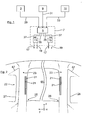
- Fig. 2 an interior of a driver's cab 22 of the truck 1 is shown.
- the driver's cab is bounded to the front by a front screen 65 and laterally by side windows 67. According to Fig.
- the two LED light bands 21 of the first signal output element 13 are fixed to an inner side 23 of a left A pillar 25 of the truck 1 at the level of a left outer mirror 27, while the two LED light bands 21 of the second signal output element 15 on an inner side 23 of a right A -Säule 26 of the truck 1 at the level of a right exterior mirror 28 set are.
- the LED strip lights 21 in a lane change for the driver of the truck 1 are clearly visible.
- the monitoring device 3 If one or more vehicles on a side lane are detected by the monitoring device 3, this is communicated to the control device 5 by means of a monitoring signal 29. Similarly, the control device 5, the operation of the direction indicator 11 is transmitted by means of a direction indicator signal 31. A detection of a lane change of the truck 1 on a side lane is notified to the control device 5 by the lane change detection device 9 with a lane change signal 33.
- the control device 5 transmits a first control signal 35 to the signal output element 13 or 15, which, from the driver's point of view seen, on the side of the truck 1, that is left or right, is arranged, in the direction of the lane change takes place.
- This signal output element 13 or 15 then outputs the first warning signal 17.
- the control device 5 does not transmit the first control signal 35 but a second control signal 37 to the signal output element 13 or 15. The signal output element 13 or 15 then outputs the second warning signal 19 off.
- FIG. 3a to 3c an overhull maneuver is shown in which the lorry 1 traveling on a lane 39 is overtaken by a vehicle 43 traveling on a side lane 41 adjoining the lane 39 of the lorry 1 laterally from behind.
- the driver of the truck 1 has the direction indicator 11 of the truck 1 is operated so that it announces a lane change on the side track 41.
- the vehicle 43 is behind a laterally adjacent to the truck 1, and hatched here shown truck side area 45.
- the monitoring device 3 of the truck 1 can not detect the vehicle 43 here, since it is designed so that it detects only vehicles, which are located in the truck side area 45 or enter within a defined period, here for example 3 seconds, in the truck side area 45.
- a second Matterhohlmanöver is shown in which the lorry driving on a lane 49 1 overtakes a on a laterally adjacent to the lane 49 side lane 51 trucks 53 from behind.
- the driver of the truck 1 has the direction indicator 11 is actuated so that it announces a lane change on the side lane 51.
- Fig. 4a is the truck 53 in the side region 45 of the truck 1, whereby the first visual warning signal 17 is output to the driver of the truck 1.
- Fig. 4b is the truck 53 outside the side area 45, so that the first warning signal 17 is no longer issued to the driver of the truck 1.
- the driver of the truck 1, as in Fig. 4c shown at not issued warning signals 17 and 19 safely complete the lane change from the lane 45 on the side lane 51.
- Fig. 5a to 5c a traffic situation in which the truck 1 is overtaken by a vehicle 55, which is not on a side adjacent to a lane 57 of the truck 1 side track 59, but on a, seen in the vehicle transverse direction y, outside of the side track 59 adjacent outer track 61.
- the driver of the truck 1 performs a lane change on the side track 59 during this overtaking.
- the monitoring device 3 always sets the side area 45 both in a lorry 1 driving the lane 57 and in a lane change of the lorry 1 in such a way that it starts from the truck 1 extends to an outer lane marking 63 of the side track 59.
- the monitoring device 3 thus does not detect the vehicle 55 traveling on the outside lane 61, so that in this safe traffic situation no warning signal 17 or 19 is output to the driver of the lorry 1.
Landscapes
- Engineering & Computer Science (AREA)
- Automation & Control Theory (AREA)
- Mechanical Engineering (AREA)
- Transportation (AREA)
- Human Computer Interaction (AREA)
- Traffic Control Systems (AREA)
Applications Claiming Priority (1)
| Application Number | Priority Date | Filing Date | Title |
|---|---|---|---|
| DE102014001115.1A DE102014001115A1 (de) | 2014-01-28 | 2014-01-28 | Verfahren und Fahrerassistenzsystem zur Unterstützung eines Fahrers eines Kraftfahrzeuges bei einem Fahrspurwechsel |
Publications (3)
| Publication Number | Publication Date |
|---|---|
| EP2899083A2 true EP2899083A2 (fr) | 2015-07-29 |
| EP2899083A3 EP2899083A3 (fr) | 2016-08-31 |
| EP2899083B1 EP2899083B1 (fr) | 2022-04-20 |
Family
ID=52013809
Family Applications (1)
| Application Number | Title | Priority Date | Filing Date |
|---|---|---|---|
| EP14003893.6A Active EP2899083B1 (fr) | 2014-01-28 | 2014-11-19 | Procédé et système d'assistance du conducteur pour l'assistance d'un conducteur de véhicule automobile lors d'un changement de voie de circulation |
Country Status (2)
| Country | Link |
|---|---|
| EP (1) | EP2899083B1 (fr) |
| DE (1) | DE102014001115A1 (fr) |
Cited By (7)
| Publication number | Priority date | Publication date | Assignee | Title |
|---|---|---|---|---|
| WO2017144382A1 (fr) * | 2016-02-24 | 2017-08-31 | Bayerische Motoren Werke Aktiengesellschaft | Dispositif et procédé d'assistance au guidage latéral pour un véhicule routier |
| EP3342671A1 (fr) * | 2016-12-30 | 2018-07-04 | Hyundai Motor Company | Appareil et procédé de mise en oeuvre d'un système d'aide de décision sur un changement de voie |
| EP3342672A1 (fr) * | 2016-12-30 | 2018-07-04 | Hyundai Motor Company | Appareil et procédé de mise en oeuvre d'un système d'aide de décision sur un changement de voie |
| EP3372449A1 (fr) * | 2017-03-08 | 2018-09-12 | MAN Truck & Bus AG | Technologie de surveillance d'une zone d'angle mort |
| CN108698612A (zh) * | 2016-02-24 | 2018-10-23 | 宝马股份公司 | 用于公路车辆的横向引导辅助的设备 |
| CN110462707A (zh) * | 2017-03-24 | 2019-11-15 | 奔迪士商业运输系统公司 | 用于在车道偏离告警系统中设置干预区的控制器和方法 |
| US11423783B2 (en) | 2016-08-30 | 2022-08-23 | Hyundai Motor Company | Apparatus and method for implementing LCDAS |
Families Citing this family (2)
| Publication number | Priority date | Publication date | Assignee | Title |
|---|---|---|---|---|
| JP6958001B2 (ja) * | 2017-06-09 | 2021-11-02 | トヨタ自動車株式会社 | 車線変更支援装置 |
| CN113920734B (zh) * | 2021-10-20 | 2023-02-28 | 长安大学 | 一种基于logistics模型的变道预警方法 |
Citations (1)
| Publication number | Priority date | Publication date | Assignee | Title |
|---|---|---|---|---|
| EP1312506B1 (fr) | 2001-11-07 | 2005-12-14 | C.R.F. Società Consortile per Azioni | Méthode et procédé d'assistance du conducteur d'un véhicule automobile dans les manoeuvres de changement de voie |
Family Cites Families (5)
| Publication number | Priority date | Publication date | Assignee | Title |
|---|---|---|---|---|
| WO2006092431A1 (fr) * | 2005-03-03 | 2006-09-08 | Continental Teves Ag & Co. Ohg | Procede et dispositif d'evitement d'une collision lors d'un changement de voie d'un vehicule |
| DE102005036714A1 (de) * | 2005-08-04 | 2007-02-08 | Daimlerchrysler Ag | Verfahren zur Unterstützung des Fahrers eines Fahrzeugs bei einem Spurwechsel und Fahrerassistenzsystem zur Durchführung des Verfahrens |
| DE102011016771A1 (de) * | 2011-04-12 | 2012-10-18 | Daimler Ag | Vorrichtung zur Bedienung einer Fahrspurwechselunterstützung in einem Fahrzeug |
| DE102011080928B4 (de) * | 2011-08-12 | 2025-09-18 | Robert Bosch Gmbh | Verfahren zur Unterstützung eines Fahrers eines Kraftfahrzeugs |
| DE102011116822B4 (de) * | 2011-10-25 | 2023-12-07 | Man Truck & Bus Se | Überwachungssystem zur Überwachung des Umfeldes von Fahrzeugen, insbesondere von Kraft- und/oder Nutzfahrzeugen |
-
2014
- 2014-01-28 DE DE102014001115.1A patent/DE102014001115A1/de not_active Withdrawn
- 2014-11-19 EP EP14003893.6A patent/EP2899083B1/fr active Active
Patent Citations (1)
| Publication number | Priority date | Publication date | Assignee | Title |
|---|---|---|---|---|
| EP1312506B1 (fr) | 2001-11-07 | 2005-12-14 | C.R.F. Società Consortile per Azioni | Méthode et procédé d'assistance du conducteur d'un véhicule automobile dans les manoeuvres de changement de voie |
Cited By (19)
| Publication number | Priority date | Publication date | Assignee | Title |
|---|---|---|---|---|
| US10885789B2 (en) | 2016-02-24 | 2021-01-05 | Bayerische Motoren Werke Aktiengesellschaft | Device and method for lateral guidance assistance for a road vehicle |
| US20180366002A1 (en) * | 2016-02-24 | 2018-12-20 | Bayerische Motoren Werke Aktiengesellschaft | Device and Method for Lateral Guidance Assistance for a Road Vehicle |
| CN108698601A (zh) * | 2016-02-24 | 2018-10-23 | 宝马股份公司 | 用于公路车辆的横向引导辅助的设备和方法 |
| CN108698612A (zh) * | 2016-02-24 | 2018-10-23 | 宝马股份公司 | 用于公路车辆的横向引导辅助的设备 |
| US11312376B2 (en) | 2016-02-24 | 2022-04-26 | Bayerische Motoren Werke Aktiengesellschaft | Device for lateral guidance assistance for a road vehicle |
| CN108698612B (zh) * | 2016-02-24 | 2022-01-14 | 宝马股份公司 | 机动车和控制单元以及用于横向引导辅助的设备和方法 |
| WO2017144382A1 (fr) * | 2016-02-24 | 2017-08-31 | Bayerische Motoren Werke Aktiengesellschaft | Dispositif et procédé d'assistance au guidage latéral pour un véhicule routier |
| US11423783B2 (en) | 2016-08-30 | 2022-08-23 | Hyundai Motor Company | Apparatus and method for implementing LCDAS |
| US11069244B2 (en) | 2016-12-30 | 2021-07-20 | Hyundai Motor Company | Apparatus and method for implementing LCDAS |
| EP3342672A1 (fr) * | 2016-12-30 | 2018-07-04 | Hyundai Motor Company | Appareil et procédé de mise en oeuvre d'un système d'aide de décision sur un changement de voie |
| CN108275155A (zh) * | 2016-12-30 | 2018-07-13 | 现代自动车株式会社 | 换道决策辅助系统设备和控制方法 |
| EP3342671A1 (fr) * | 2016-12-30 | 2018-07-04 | Hyundai Motor Company | Appareil et procédé de mise en oeuvre d'un système d'aide de décision sur un changement de voie |
| CN108263378A (zh) * | 2016-12-30 | 2018-07-10 | 现代自动车株式会社 | 用于实现换道决策辅助系统的设备和方法 |
| EP3372449A1 (fr) * | 2017-03-08 | 2018-09-12 | MAN Truck & Bus AG | Technologie de surveillance d'une zone d'angle mort |
| US10410525B2 (en) * | 2017-03-08 | 2019-09-10 | Man Truck & Bus Ag | Technique for monitoring a blind spot zone |
| CN108569283A (zh) * | 2017-03-08 | 2018-09-25 | 曼卡车和巴士股份公司 | 用于监视盲角区域的技术 |
| CN108569283B (zh) * | 2017-03-08 | 2023-03-14 | 曼卡车和巴士股份公司 | 用于监视盲角区域的技术 |
| CN110462707A (zh) * | 2017-03-24 | 2019-11-15 | 奔迪士商业运输系统公司 | 用于在车道偏离告警系统中设置干预区的控制器和方法 |
| CN110462707B (zh) * | 2017-03-24 | 2023-01-13 | 奔迪士商业运输系统公司 | 用于在车道偏离告警系统中设置干预区的控制器和方法 |
Also Published As
| Publication number | Publication date |
|---|---|
| DE102014001115A1 (de) | 2015-07-30 |
| EP2899083A3 (fr) | 2016-08-31 |
| EP2899083B1 (fr) | 2022-04-20 |
Similar Documents
| Publication | Publication Date | Title |
|---|---|---|
| EP2899083B1 (fr) | Procédé et système d'assistance du conducteur pour l'assistance d'un conducteur de véhicule automobile lors d'un changement de voie de circulation | |
| DE102010038180B4 (de) | Fahrunterstützungsvorrichtung für Fahrzeuge in einem Kreuzungsbereich | |
| DE102013213064B4 (de) | Verfahren und Vorrichtung zum autonomen Einparken eines Fahrzeugs mit externer Überwachung | |
| DE102011116822B4 (de) | Überwachungssystem zur Überwachung des Umfeldes von Fahrzeugen, insbesondere von Kraft- und/oder Nutzfahrzeugen | |
| EP2464992B1 (fr) | Collision surpervision pour véhicule | |
| DE102013222467A1 (de) | Verfahren und Vorrichtung zur Querführungsunterstützung eines Kraftfahrzeugs | |
| DE102012023630B4 (de) | Verfahren zur Information eines Fahrzeugführers hinsichtlich eines von einem auf Umgebungsdaten basierten Fahrerassistenzsystems eines Fahrzeugs ausgeführten automatischen Fahrmanövers | |
| EP2319732A2 (fr) | Dispositif et procédé de surveillance et de signalisation de situations de circulation et d'états de fonctionnement dans un véhicule et dans l'environnement du véhicule | |
| EP3592604B1 (fr) | Véhicule automobile comprenant un module d'éclairage servant à générer un symbole | |
| DE102012108563A1 (de) | Verfahren und Vorrichtungen zur Kollisionswarnung bei Fahrstreifenwechseln | |
| EP3242815B1 (fr) | Procédé et système d'aide à la conduite pour assister le conducteur d'un véhicule | |
| DE102014204316B4 (de) | Optische Signaleinrichtung für ein Kraftfahrzeug und Kraftfahrzeug | |
| DE102014008980A1 (de) | Verfahren zur Kollisionsvermeidung von Fahrzeugen in Überholsituationen mit Gegenverkehr und ein Fahrzeug | |
| EP1516301A1 (fr) | Procede et dispositif pour informer un conducteur ou intervenir sur un conducteur deviant de sa trajectoire sur une voie de circulation | |
| DE102009052590A1 (de) | Vorrichtung und Verfahren zur Überwachung und Signalisierung von Verkehrssituationen und Betriebszuständen in einem Fahrzeug und im Umfeld des Fahrzeugs | |
| DE102012201046A1 (de) | Verfahren und Vorrichtung zur Unterstützung eines Fahrers | |
| DE102013207581A1 (de) | Verfahren zum automatischen Betätigen eines Fahrtrichtungsanzeigers eines Kraftfahrzeuges | |
| DE102011106082A1 (de) | Verfahren zur wenigstens teilweise automatischen Einleitung eines kollisionsvermeidenden Fahrmanövers durch automatischen Bremseingriff | |
| DE102009033066A1 (de) | Fahrerassistenzeinrichtung für ein Fahrzeug, Fahrzeug mit einer derartigen Fahrerassistenzeinrichtung sowie Verfahren zum Unterstützen eines Fahrers eines Fahrzeugs | |
| EP3372449B1 (fr) | Technologie de surveillance d'une zone d'angle mort | |
| DE102016225969B4 (de) | Verfahren zum Betreiben einer Anzeigeeinrichtung eines pilotierten Kraftfahrzeugs | |
| DE102008011366A1 (de) | Kraftfahrzeug | |
| DE102014220324A1 (de) | Head-up-Display zur Überwachung eines Verkehrsraums | |
| DE102006002662A1 (de) | Sicherheitseinrichtung für ein Fahrzeug und Verfahren zum Betrieb einer Sicherheitseinrichtung | |
| DE102014222211B4 (de) | Kraftfahrzeug mit einem einen Rückspiegel aufweisenden Anzeigesystem und Verfahren zur Informationsdarstellung |
Legal Events
| Date | Code | Title | Description |
|---|---|---|---|
| PUAI | Public reference made under article 153(3) epc to a published international application that has entered the european phase |
Free format text: ORIGINAL CODE: 0009012 |
|
| 17P | Request for examination filed |
Effective date: 20141119 |
|
| AK | Designated contracting states |
Kind code of ref document: A2 Designated state(s): AL AT BE BG CH CY CZ DE DK EE ES FI FR GB GR HR HU IE IS IT LI LT LU LV MC MK MT NL NO PL PT RO RS SE SI SK SM TR |
|
| AX | Request for extension of the european patent |
Extension state: BA ME |
|
| PUAL | Search report despatched |
Free format text: ORIGINAL CODE: 0009013 |
|
| AK | Designated contracting states |
Kind code of ref document: A3 Designated state(s): AL AT BE BG CH CY CZ DE DK EE ES FI FR GB GR HR HU IE IS IT LI LT LU LV MC MK MT NL NO PL PT RO RS SE SI SK SM TR |
|
| AX | Request for extension of the european patent |
Extension state: BA ME |
|
| RIC1 | Information provided on ipc code assigned before grant |
Ipc: B60W 50/14 20120101ALI20160725BHEP Ipc: B60W 30/18 20120101AFI20160725BHEP |
|
| STAA | Information on the status of an ep patent application or granted ep patent |
Free format text: STATUS: REQUEST FOR EXAMINATION WAS MADE |
|
| 17P | Request for examination filed |
Effective date: 20170228 |
|
| RAP1 | Party data changed (applicant data changed or rights of an application transferred) |
Owner name: MAN TRUCK & BUS SE |
|
| STAA | Information on the status of an ep patent application or granted ep patent |
Free format text: STATUS: EXAMINATION IS IN PROGRESS |
|
| 17Q | First examination report despatched |
Effective date: 20210409 |
|
| GRAP | Despatch of communication of intention to grant a patent |
Free format text: ORIGINAL CODE: EPIDOSNIGR1 |
|
| STAA | Information on the status of an ep patent application or granted ep patent |
Free format text: STATUS: GRANT OF PATENT IS INTENDED |
|
| INTG | Intention to grant announced |
Effective date: 20211115 |
|
| GRAS | Grant fee paid |
Free format text: ORIGINAL CODE: EPIDOSNIGR3 |
|
| AK | Designated contracting states |
Kind code of ref document: B1 Designated state(s): AL AT BE BG CH CY CZ DE DK EE ES FI FR GB GR HR HU IE IS IT LI LT LU LV MC MK MT NL NO PL PT RO RS SE SI SK SM TR |
|
| GRAA | (expected) grant |
Free format text: ORIGINAL CODE: 0009210 |
|
| REG | Reference to a national code |
Ref country code: GB Ref legal event code: FG4D Free format text: NOT ENGLISH |
|
| STAA | Information on the status of an ep patent application or granted ep patent |
Free format text: STATUS: THE PATENT HAS BEEN GRANTED |
|
| REG | Reference to a national code |
Ref country code: CH Ref legal event code: EP |
|
| REG | Reference to a national code |
Ref country code: IE Ref legal event code: FG4D Free format text: LANGUAGE OF EP DOCUMENT: GERMAN |
|
| REG | Reference to a national code |
Ref country code: DE Ref legal event code: R096 Ref document number: 502014016201 Country of ref document: DE |
|
| REG | Reference to a national code |
Ref country code: AT Ref legal event code: REF Ref document number: 1484953 Country of ref document: AT Kind code of ref document: T Effective date: 20220515 |
|
| REG | Reference to a national code |
Ref country code: NL Ref legal event code: FP |
|
| REG | Reference to a national code |
Ref country code: SE Ref legal event code: TRGR |
|
| REG | Reference to a national code |
Ref country code: LT Ref legal event code: MG9D |
|
| PG25 | Lapsed in a contracting state [announced via postgrant information from national office to epo] |
Ref country code: PT Free format text: LAPSE BECAUSE OF FAILURE TO SUBMIT A TRANSLATION OF THE DESCRIPTION OR TO PAY THE FEE WITHIN THE PRESCRIBED TIME-LIMIT Effective date: 20220822 Ref country code: NO Free format text: LAPSE BECAUSE OF FAILURE TO SUBMIT A TRANSLATION OF THE DESCRIPTION OR TO PAY THE FEE WITHIN THE PRESCRIBED TIME-LIMIT Effective date: 20220720 Ref country code: LT Free format text: LAPSE BECAUSE OF FAILURE TO SUBMIT A TRANSLATION OF THE DESCRIPTION OR TO PAY THE FEE WITHIN THE PRESCRIBED TIME-LIMIT Effective date: 20220420 Ref country code: HR Free format text: LAPSE BECAUSE OF FAILURE TO SUBMIT A TRANSLATION OF THE DESCRIPTION OR TO PAY THE FEE WITHIN THE PRESCRIBED TIME-LIMIT Effective date: 20220420 Ref country code: GR Free format text: LAPSE BECAUSE OF FAILURE TO SUBMIT A TRANSLATION OF THE DESCRIPTION OR TO PAY THE FEE WITHIN THE PRESCRIBED TIME-LIMIT Effective date: 20220721 Ref country code: FI Free format text: LAPSE BECAUSE OF FAILURE TO SUBMIT A TRANSLATION OF THE DESCRIPTION OR TO PAY THE FEE WITHIN THE PRESCRIBED TIME-LIMIT Effective date: 20220420 Ref country code: ES Free format text: LAPSE BECAUSE OF FAILURE TO SUBMIT A TRANSLATION OF THE DESCRIPTION OR TO PAY THE FEE WITHIN THE PRESCRIBED TIME-LIMIT Effective date: 20220420 Ref country code: BG Free format text: LAPSE BECAUSE OF FAILURE TO SUBMIT A TRANSLATION OF THE DESCRIPTION OR TO PAY THE FEE WITHIN THE PRESCRIBED TIME-LIMIT Effective date: 20220720 |
|
| PG25 | Lapsed in a contracting state [announced via postgrant information from national office to epo] |
Ref country code: RS Free format text: LAPSE BECAUSE OF FAILURE TO SUBMIT A TRANSLATION OF THE DESCRIPTION OR TO PAY THE FEE WITHIN THE PRESCRIBED TIME-LIMIT Effective date: 20220420 Ref country code: PL Free format text: LAPSE BECAUSE OF FAILURE TO SUBMIT A TRANSLATION OF THE DESCRIPTION OR TO PAY THE FEE WITHIN THE PRESCRIBED TIME-LIMIT Effective date: 20220420 Ref country code: LV Free format text: LAPSE BECAUSE OF FAILURE TO SUBMIT A TRANSLATION OF THE DESCRIPTION OR TO PAY THE FEE WITHIN THE PRESCRIBED TIME-LIMIT Effective date: 20220420 Ref country code: IS Free format text: LAPSE BECAUSE OF FAILURE TO SUBMIT A TRANSLATION OF THE DESCRIPTION OR TO PAY THE FEE WITHIN THE PRESCRIBED TIME-LIMIT Effective date: 20220820 |
|
| REG | Reference to a national code |
Ref country code: DE Ref legal event code: R097 Ref document number: 502014016201 Country of ref document: DE |
|
| PG25 | Lapsed in a contracting state [announced via postgrant information from national office to epo] |
Ref country code: SM Free format text: LAPSE BECAUSE OF FAILURE TO SUBMIT A TRANSLATION OF THE DESCRIPTION OR TO PAY THE FEE WITHIN THE PRESCRIBED TIME-LIMIT Effective date: 20220420 Ref country code: SK Free format text: LAPSE BECAUSE OF FAILURE TO SUBMIT A TRANSLATION OF THE DESCRIPTION OR TO PAY THE FEE WITHIN THE PRESCRIBED TIME-LIMIT Effective date: 20220420 Ref country code: RO Free format text: LAPSE BECAUSE OF FAILURE TO SUBMIT A TRANSLATION OF THE DESCRIPTION OR TO PAY THE FEE WITHIN THE PRESCRIBED TIME-LIMIT Effective date: 20220420 Ref country code: EE Free format text: LAPSE BECAUSE OF FAILURE TO SUBMIT A TRANSLATION OF THE DESCRIPTION OR TO PAY THE FEE WITHIN THE PRESCRIBED TIME-LIMIT Effective date: 20220420 Ref country code: DK Free format text: LAPSE BECAUSE OF FAILURE TO SUBMIT A TRANSLATION OF THE DESCRIPTION OR TO PAY THE FEE WITHIN THE PRESCRIBED TIME-LIMIT Effective date: 20220420 Ref country code: CZ Free format text: LAPSE BECAUSE OF FAILURE TO SUBMIT A TRANSLATION OF THE DESCRIPTION OR TO PAY THE FEE WITHIN THE PRESCRIBED TIME-LIMIT Effective date: 20220420 |
|
| PLBE | No opposition filed within time limit |
Free format text: ORIGINAL CODE: 0009261 |
|
| STAA | Information on the status of an ep patent application or granted ep patent |
Free format text: STATUS: NO OPPOSITION FILED WITHIN TIME LIMIT |
|
| 26N | No opposition filed |
Effective date: 20230123 |
|
| PG25 | Lapsed in a contracting state [announced via postgrant information from national office to epo] |
Ref country code: AL Free format text: LAPSE BECAUSE OF FAILURE TO SUBMIT A TRANSLATION OF THE DESCRIPTION OR TO PAY THE FEE WITHIN THE PRESCRIBED TIME-LIMIT Effective date: 20220420 |
|
| PG25 | Lapsed in a contracting state [announced via postgrant information from national office to epo] |
Ref country code: SI Free format text: LAPSE BECAUSE OF FAILURE TO SUBMIT A TRANSLATION OF THE DESCRIPTION OR TO PAY THE FEE WITHIN THE PRESCRIBED TIME-LIMIT Effective date: 20220420 |
|
| PG25 | Lapsed in a contracting state [announced via postgrant information from national office to epo] |
Ref country code: MC Free format text: LAPSE BECAUSE OF FAILURE TO SUBMIT A TRANSLATION OF THE DESCRIPTION OR TO PAY THE FEE WITHIN THE PRESCRIBED TIME-LIMIT Effective date: 20220420 |
|
| REG | Reference to a national code |
Ref country code: CH Ref legal event code: PL |
|
| GBPC | Gb: european patent ceased through non-payment of renewal fee |
Effective date: 20221119 |
|
| REG | Reference to a national code |
Ref country code: BE Ref legal event code: MM Effective date: 20221130 |
|
| PG25 | Lapsed in a contracting state [announced via postgrant information from national office to epo] |
Ref country code: LI Free format text: LAPSE BECAUSE OF NON-PAYMENT OF DUE FEES Effective date: 20221130 Ref country code: CH Free format text: LAPSE BECAUSE OF NON-PAYMENT OF DUE FEES Effective date: 20221130 |
|
| PG25 | Lapsed in a contracting state [announced via postgrant information from national office to epo] |
Ref country code: LU Free format text: LAPSE BECAUSE OF NON-PAYMENT OF DUE FEES Effective date: 20221119 |
|
| PG25 | Lapsed in a contracting state [announced via postgrant information from national office to epo] |
Ref country code: IE Free format text: LAPSE BECAUSE OF NON-PAYMENT OF DUE FEES Effective date: 20221119 Ref country code: GB Free format text: LAPSE BECAUSE OF NON-PAYMENT OF DUE FEES Effective date: 20221119 |
|
| PG25 | Lapsed in a contracting state [announced via postgrant information from national office to epo] |
Ref country code: BE Free format text: LAPSE BECAUSE OF NON-PAYMENT OF DUE FEES Effective date: 20221130 |
|
| REG | Reference to a national code |
Ref country code: AT Ref legal event code: MM01 Ref document number: 1484953 Country of ref document: AT Kind code of ref document: T Effective date: 20221119 |
|
| PG25 | Lapsed in a contracting state [announced via postgrant information from national office to epo] |
Ref country code: AT Free format text: LAPSE BECAUSE OF NON-PAYMENT OF DUE FEES Effective date: 20221119 |
|
| PG25 | Lapsed in a contracting state [announced via postgrant information from national office to epo] |
Ref country code: HU Free format text: LAPSE BECAUSE OF FAILURE TO SUBMIT A TRANSLATION OF THE DESCRIPTION OR TO PAY THE FEE WITHIN THE PRESCRIBED TIME-LIMIT; INVALID AB INITIO Effective date: 20141119 |
|
| PG25 | Lapsed in a contracting state [announced via postgrant information from national office to epo] |
Ref country code: CY Free format text: LAPSE BECAUSE OF FAILURE TO SUBMIT A TRANSLATION OF THE DESCRIPTION OR TO PAY THE FEE WITHIN THE PRESCRIBED TIME-LIMIT Effective date: 20220420 |
|
| PG25 | Lapsed in a contracting state [announced via postgrant information from national office to epo] |
Ref country code: MK Free format text: LAPSE BECAUSE OF FAILURE TO SUBMIT A TRANSLATION OF THE DESCRIPTION OR TO PAY THE FEE WITHIN THE PRESCRIBED TIME-LIMIT Effective date: 20220420 |
|
| PG25 | Lapsed in a contracting state [announced via postgrant information from national office to epo] |
Ref country code: MT Free format text: LAPSE BECAUSE OF FAILURE TO SUBMIT A TRANSLATION OF THE DESCRIPTION OR TO PAY THE FEE WITHIN THE PRESCRIBED TIME-LIMIT Effective date: 20220420 |
|
| PG25 | Lapsed in a contracting state [announced via postgrant information from national office to epo] |
Ref country code: BG Free format text: LAPSE BECAUSE OF FAILURE TO SUBMIT A TRANSLATION OF THE DESCRIPTION OR TO PAY THE FEE WITHIN THE PRESCRIBED TIME-LIMIT Effective date: 20220420 |
|
| PG25 | Lapsed in a contracting state [announced via postgrant information from national office to epo] |
Ref country code: BG Free format text: LAPSE BECAUSE OF FAILURE TO SUBMIT A TRANSLATION OF THE DESCRIPTION OR TO PAY THE FEE WITHIN THE PRESCRIBED TIME-LIMIT Effective date: 20220420 |
|
| PG25 | Lapsed in a contracting state [announced via postgrant information from national office to epo] |
Ref country code: TR Free format text: LAPSE BECAUSE OF FAILURE TO SUBMIT A TRANSLATION OF THE DESCRIPTION OR TO PAY THE FEE WITHIN THE PRESCRIBED TIME-LIMIT Effective date: 20220420 |
|
| PGFP | Annual fee paid to national office [announced via postgrant information from national office to epo] |
Ref country code: NL Payment date: 20251124 Year of fee payment: 12 |
|
| PGFP | Annual fee paid to national office [announced via postgrant information from national office to epo] |
Ref country code: DE Payment date: 20251126 Year of fee payment: 12 |
|
| PGFP | Annual fee paid to national office [announced via postgrant information from national office to epo] |
Ref country code: IT Payment date: 20251121 Year of fee payment: 12 |
|
| PGFP | Annual fee paid to national office [announced via postgrant information from national office to epo] |
Ref country code: FR Payment date: 20251124 Year of fee payment: 12 |
|
| PGFP | Annual fee paid to national office [announced via postgrant information from national office to epo] |
Ref country code: SE Payment date: 20251124 Year of fee payment: 12 |