EP2899353B1 - Streifenförmiges Stütz- und Isolierelement zur Abstützung und Isolierung eines Fensterrahmens - Google Patents
Streifenförmiges Stütz- und Isolierelement zur Abstützung und Isolierung eines Fensterrahmens Download PDFInfo
- Publication number
- EP2899353B1 EP2899353B1 EP14152543.6A EP14152543A EP2899353B1 EP 2899353 B1 EP2899353 B1 EP 2899353B1 EP 14152543 A EP14152543 A EP 14152543A EP 2899353 B1 EP2899353 B1 EP 2899353B1
- Authority
- EP
- European Patent Office
- Prior art keywords
- supporting
- insulating
- limb
- element according
- insulating element
- Prior art date
- Legal status (The legal status is an assumption and is not a legal conclusion. Google has not performed a legal analysis and makes no representation as to the accuracy of the status listed.)
- Active
Links
Images


Classifications
-
- E—FIXED CONSTRUCTIONS
- E06—DOORS, WINDOWS, SHUTTERS, OR ROLLER BLINDS IN GENERAL; LADDERS
- E06B—FIXED OR MOVABLE CLOSURES FOR OPENINGS IN BUILDINGS, VEHICLES, FENCES OR LIKE ENCLOSURES IN GENERAL, e.g. DOORS, WINDOWS, BLINDS, GATES
- E06B1/00—Border constructions of openings in walls, floors, or ceilings; Frames to be rigidly mounted in such openings
- E06B1/56—Fastening frames to the border of openings or to similar contiguous frames
- E06B1/58—Fastening frames to the border of openings or to similar contiguous frames by filling up the joints, e.g. by cementing
-
- E—FIXED CONSTRUCTIONS
- E06—DOORS, WINDOWS, SHUTTERS, OR ROLLER BLINDS IN GENERAL; LADDERS
- E06B—FIXED OR MOVABLE CLOSURES FOR OPENINGS IN BUILDINGS, VEHICLES, FENCES OR LIKE ENCLOSURES IN GENERAL, e.g. DOORS, WINDOWS, BLINDS, GATES
- E06B1/00—Border constructions of openings in walls, floors, or ceilings; Frames to be rigidly mounted in such openings
- E06B1/003—Cavity wall closers; Fastening door or window frames in cavity walls
-
- E—FIXED CONSTRUCTIONS
- E06—DOORS, WINDOWS, SHUTTERS, OR ROLLER BLINDS IN GENERAL; LADDERS
- E06B—FIXED OR MOVABLE CLOSURES FOR OPENINGS IN BUILDINGS, VEHICLES, FENCES OR LIKE ENCLOSURES IN GENERAL, e.g. DOORS, WINDOWS, BLINDS, GATES
- E06B1/00—Border constructions of openings in walls, floors, or ceilings; Frames to be rigidly mounted in such openings
- E06B1/04—Frames for doors, windows, or the like to be fixed in openings
- E06B1/36—Frames uniquely adapted for windows
-
- E—FIXED CONSTRUCTIONS
- E06—DOORS, WINDOWS, SHUTTERS, OR ROLLER BLINDS IN GENERAL; LADDERS
- E06B—FIXED OR MOVABLE CLOSURES FOR OPENINGS IN BUILDINGS, VEHICLES, FENCES OR LIKE ENCLOSURES IN GENERAL, e.g. DOORS, WINDOWS, BLINDS, GATES
- E06B1/00—Border constructions of openings in walls, floors, or ceilings; Frames to be rigidly mounted in such openings
- E06B1/62—Tightening or covering joints between the border of openings and the frame or between contiguous frames
-
- E—FIXED CONSTRUCTIONS
- E06—DOORS, WINDOWS, SHUTTERS, OR ROLLER BLINDS IN GENERAL; LADDERS
- E06B—FIXED OR MOVABLE CLOSURES FOR OPENINGS IN BUILDINGS, VEHICLES, FENCES OR LIKE ENCLOSURES IN GENERAL, e.g. DOORS, WINDOWS, BLINDS, GATES
- E06B3/00—Window sashes, door leaves, or like elements for closing wall or like openings; Layout of fixed or moving closures, e.g. windows in wall or like openings; Features of rigidly-mounted outer frames relating to the mounting of wing frames
- E06B3/04—Wing frames not characterised by the manner of movement
- E06B3/263—Frames with special provision for insulation
- E06B3/2632—Frames with special provision for insulation with arrangements reducing the heat transmission, other than an interruption in a metal section
-
- E—FIXED CONSTRUCTIONS
- E06—DOORS, WINDOWS, SHUTTERS, OR ROLLER BLINDS IN GENERAL; LADDERS
- E06B—FIXED OR MOVABLE CLOSURES FOR OPENINGS IN BUILDINGS, VEHICLES, FENCES OR LIKE ENCLOSURES IN GENERAL, e.g. DOORS, WINDOWS, BLINDS, GATES
- E06B3/00—Window sashes, door leaves, or like elements for closing wall or like openings; Layout of fixed or moving closures, e.g. windows in wall or like openings; Features of rigidly-mounted outer frames relating to the mounting of wing frames
- E06B3/04—Wing frames not characterised by the manner of movement
- E06B3/263—Frames with special provision for insulation
- E06B3/273—Frames with special provision for insulation with prefabricated insulating elements held in position by deformation of portions of the metal frame members
-
- E—FIXED CONSTRUCTIONS
- E06—DOORS, WINDOWS, SHUTTERS, OR ROLLER BLINDS IN GENERAL; LADDERS
- E06B—FIXED OR MOVABLE CLOSURES FOR OPENINGS IN BUILDINGS, VEHICLES, FENCES OR LIKE ENCLOSURES IN GENERAL, e.g. DOORS, WINDOWS, BLINDS, GATES
- E06B1/00—Border constructions of openings in walls, floors, or ceilings; Frames to be rigidly mounted in such openings
- E06B1/56—Fastening frames to the border of openings or to similar contiguous frames
- E06B1/60—Fastening frames to the border of openings or to similar contiguous frames by mechanical means, e.g. anchoring means
-
- E—FIXED CONSTRUCTIONS
- E06—DOORS, WINDOWS, SHUTTERS, OR ROLLER BLINDS IN GENERAL; LADDERS
- E06B—FIXED OR MOVABLE CLOSURES FOR OPENINGS IN BUILDINGS, VEHICLES, FENCES OR LIKE ENCLOSURES IN GENERAL, e.g. DOORS, WINDOWS, BLINDS, GATES
- E06B1/00—Border constructions of openings in walls, floors, or ceilings; Frames to be rigidly mounted in such openings
- E06B1/62—Tightening or covering joints between the border of openings and the frame or between contiguous frames
- E06B2001/626—Tightening or covering joints between the border of openings and the frame or between contiguous frames comprising expanding foam strips
-
- E—FIXED CONSTRUCTIONS
- E06—DOORS, WINDOWS, SHUTTERS, OR ROLLER BLINDS IN GENERAL; LADDERS
- E06B—FIXED OR MOVABLE CLOSURES FOR OPENINGS IN BUILDINGS, VEHICLES, FENCES OR LIKE ENCLOSURES IN GENERAL, e.g. DOORS, WINDOWS, BLINDS, GATES
- E06B1/00—Border constructions of openings in walls, floors, or ceilings; Frames to be rigidly mounted in such openings
- E06B1/70—Sills; Thresholds
- E06B2001/707—Thresholds with special provision for insulation
-
- E—FIXED CONSTRUCTIONS
- E06—DOORS, WINDOWS, SHUTTERS, OR ROLLER BLINDS IN GENERAL; LADDERS
- E06B—FIXED OR MOVABLE CLOSURES FOR OPENINGS IN BUILDINGS, VEHICLES, FENCES OR LIKE ENCLOSURES IN GENERAL, e.g. DOORS, WINDOWS, BLINDS, GATES
- E06B3/00—Window sashes, door leaves, or like elements for closing wall or like openings; Layout of fixed or moving closures, e.g. windows in wall or like openings; Features of rigidly-mounted outer frames relating to the mounting of wing frames
- E06B3/04—Wing frames not characterised by the manner of movement
- E06B3/263—Frames with special provision for insulation
- E06B3/2632—Frames with special provision for insulation with arrangements reducing the heat transmission, other than an interruption in a metal section
- E06B2003/26321—Frames with special provision for insulation with arrangements reducing the heat transmission, other than an interruption in a metal section with additional prefab insulating materials in the hollow space
-
- E—FIXED CONSTRUCTIONS
- E06—DOORS, WINDOWS, SHUTTERS, OR ROLLER BLINDS IN GENERAL; LADDERS
- E06B—FIXED OR MOVABLE CLOSURES FOR OPENINGS IN BUILDINGS, VEHICLES, FENCES OR LIKE ENCLOSURES IN GENERAL, e.g. DOORS, WINDOWS, BLINDS, GATES
- E06B3/00—Window sashes, door leaves, or like elements for closing wall or like openings; Layout of fixed or moving closures, e.g. windows in wall or like openings; Features of rigidly-mounted outer frames relating to the mounting of wing frames
- E06B3/04—Wing frames not characterised by the manner of movement
- E06B3/263—Frames with special provision for insulation
- E06B2003/26349—Details of insulating strips
Definitions
- the invention relates to a strip-shaped supporting and insulating element for supporting and insulating a window frame.
- Such supporting and insulating elements have been used for some years in conjunction with thermal insulation composite systems to artificially extend a wall opening for a window to the outside.
- a support member made of load-bearing rigid foam is laterally screwed to the wall and serves, in particular at the bottom, the support of the window frame to be used.
- a pretext with the inner wall forms a gap in which the support member is arranged.
- the load bearing support member with more or less triangular cross-section is supplemented by an insulating part, which consists for example of hard flexible foam and together with the support member forms a two-part body with preferably cuboidal cross-section.
- the insulating part must be separately connected after screwing the support member to the inner wall with the support member.
- DE 10 2004 038 246 shows a support and insulating element according to the preamble of claim 1.
- the present invention has for its object to provide a support and insulating, which allows a particularly simple transport and installation.
- the strip-shaped supporting and insulating element for supporting and insulating a window frame comprises a support part having a first longitudinal side surface which abuts against a wall to which the support part is to be fastened and a second longitudinal side surface which in FIG Is substantially perpendicular to the first side surface and serves to support the window frame, wherein the support member is formed of a load-bearing material.
- the support and insulating member comprises an insulating member which is connected to the support member.
- the support member in this case has a first leg, which comprises the first side surface, and has a second leg, which is connected to the first leg and protrudes at an angle from the first leg.
- the insulating part is arranged in the region of an inner side surface of the first limb of the support part opposite the first side surface and with an outer edge region of the first or 10196 P 0275 EP
- the pivotal connection between the insulating part and the support member is formed by a flexible adhesive strip which is adhered to both the insulating part and the support member.
- a cost-effective and easy to handle structure is created, which allows pivoting any amount of the insulating part relative to the support member.
- At least one through-hole for receiving a fastener for securing the support member to the wall may already be provided extending from the inner side surface to the first side surface through the first leg of the support member. In this way, the craftsman is spared the step of creating the through-hole at the construction site.
- the support member is formed of a rigid foam material.
- This material has the advantage that it is very stable, on the other hand already provides a certain insulating effect.
- An example of such a material is a rigid foam based on polyurethane, such as Purenit.
- the insulating part is preferably made of foam, preferably of hard flexible foam.
- This foam should preferably be self-supporting.
- thermal insulation materials such as polystyrene, Styrodur, Styrofoam, Styrofoam or Neopur come into question.
- a particularly preferred geometry is given when the support member is formed in cross-section substantially L-shaped. This ensures that the pivoting of the insulating member is not hindered while avoiding inclined surfaces on the support member, which complicate the handling when creating through holes or when inserting fasteners in the through holes.
- the support member may be formed in cross-section substantially T-shaped. Then, the support and insulating member preferably has two insulating parts, which are arranged on both sides of the second leg.
- the second leg has the second side surface, and the first and second side surfaces also intersect at the same angle as the second leg protrudes from the first leg. This applies in particular to the design of the support member with L-shaped cross-section.
- first leg also has the second side surface, which is then arranged adjacent to the first side surface.
- This embodiment is inevitable in the support member with T-shaped cross-section, but may also be present in the support member with L-shaped cross-section.
- the sealing strip For better handling of the sealing strip is preferably held in such a case by a compression means in the compressed state, wherein the expansion of the sealing strip can be triggered by loosening or removing the compression means.
- the compression means can be dissolved or removed only in the installed state of the support and insulating, and the expansion of the sealing strip occurs only after completion of the installation work of the support and insulating member and does not hinder them.
- the compression means is a film envelope which at least partially surrounds the sealing strip. This can be easily solved or removed and can also serve in the installed state as a vapor barrier.
- the sealing strip can also be designed such that the expansion can be activated in a controlled manner, e.g. by heat, moisture or electrical impact.
- a building section equipped with supporting and insulating elements according to the invention usually comprises a wall, a front wall and an intermediate space arranged between the wall and the front wall.
- the supporting and insulating elements according to the invention are usually arranged in the space between the wall and the front wall and fastened by means of fastening elements on the wall.
- a window frame is disposed adjacent to the gap and abuts against the second side surfaces of the support member of the support and insulating members. It may also be present only a support and insulating element, which is arranged below the window frame and thus removes the weight load of the window.
- the pretext can also be provided on the wall-mounted thermal barrier coating having an opening for a window. The support and insulating then projects into this thermal barrier coating.
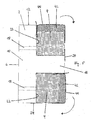
- a first embodiment of the support and insulating element according to the invention for supporting and insulating a window frame is shown.
- the support and insulating element comprises a cross-sectionally angular support member 2, with which a rectangular in cross-section insulating part 4 is connected. How best Fig. 3 it can be seen, extend both support member 2 and insulating part 4 primarily in a longitudinal direction.
- the length of a supporting and insulating element in the longitudinal direction can be chosen freely and is preferably between 10 and 150 cm.
- the support member 2 may be integrally formed or consist of two firmly interconnected sections.
- the support member 2 is configured in the illustrated embodiment in cross-section L-shaped.
- Wood or plastic can be used as the material of the support member 2, but is preferably a rigid foam material, for example based on polyurethane or polystyrene.
- the rigid foam material has a compressive stress according to DIN EN 826 in the range of 2 to 15 MPa, in particular in the range of 4 to 8 MPa.
- the bulk density of the rigid foam material should be in the range of 100 to 1200 kg / m 3 , preferably between 350 to 800 kg / m 3 .
- the thermal conductivity of the rigid foam material should be in the range of 0.05 to 0.2 W / mK, preferably in the range of 0.06 to 0.15 W / mK.
- the rigid foam material is dimensionally stable and compression-stable under the load of the window. An example of such a rigid foam material is sold under the name "Purenit®".
- the support member 2 has a first longitudinally extending side surface 6 which abuts against a wall 8 (FIG. Fig. 2 ) serves.
- the first side surface 6 is part of a first leg 10 of the support part 2.
- the support part 2 also has a second longitudinally extending side surface 12 which is substantially perpendicular to the first side surface 6 and for supporting a window frame 34 (FIG. Fig. 2 ) serves.
- the second side surface 12 is part of a second leg 16 of the support member 2, which is connected to the first leg 10 and protrudes at an angle from the first leg 10. In the example shown, the angle is 90 °.
- the first side surface 6 and the second side surface 12 abut one another along an edge and also intersect at the same angle as the two legs 10, 16, in this case at 90 °.
- each through hole 18 thus passes through the first leg 10 of the support member 2 from an inner side surface 22 opposite the first side surface 6 to the first side surface 6 Fig. 2 shows, each fastener 20 is used to attach the support member 2 and thus the support and insulating on the wall eighth
- the insulating part 4 is arranged in the region of the inner side surface 22 of the first leg 10 of the support part 2. It is preferably formed from foam, particularly preferably from hard flexible foam. As a rule, such foams are self-supporting, but can not remove any load. Examples of such materials are polystyrene, Styrodur, Styrofoam, Styrofoam or Neopur, with densities ⁇ 100 kg / m 3 , preferably ⁇ 50 kg / m 3 , which are considered as thermal insulation materials.
- the compressive strength of such heat insulation materials is preferably at most 50% of the compressive strength of the load-bearing rigid foam preferably used for the support part 2, as a rule less than 20%.
- the insulating part 4 is pivotally connected to an outer edge region of the first leg 10 of the support part 2. Likewise, it may be pivotally connected to an outer edge region of the second leg 16 of the support part 2.
- Fig. 1a an insulating position of the insulating part 4 is shown, in which the insulating part 4, the inner side surface 22 of the first leg 10 of the support member 2 at least largely covered, in the present case even completely.
- the insulating part 4 is preferably located on both the first leg 10 and the second leg 16 of the support member 2. It is particularly preferred if the support part 2 and the insulating part 4 complement each other to a rectangular cross-sectional shape.
- the supporting and insulating element is preferably also transported in this insulating position.
- Fig. 1b shows the pivoting located Isol Arthuril 4, which is on the way to a working position in which it exposes the inner side surface 22 of the first leg 10 of the support member 2 at least largely.
- the fasteners 20 can be freely inserted into the through holes 18. If no through holes 18 are present in the support member 2, the craftsman has in the working position of the insulating 4 also unobstructed access to the first leg 10 of the support member 2 and there can produce the through holes 18, before the fasteners 20 through the through holes 18 in the wall. 8 introduces.
- the swivel angle between the working position and the insulating position of the insulating part 4 is usually between 60 and 120 °, but is not subject to any restrictions.
- the pivotal connection between the insulating part 4 and support member 2 is preferably formed by a flexible adhesive strip 24 which is adhered to both the insulating part 4 and the support member 2.
- a flexible adhesive strip 24 which is adhered to both the insulating part 4 and the support member 2.
- the adhesive strip 24 in a straight overlap of a joint edge between the support member 2 and insulating part. 4 educated. However, there are many other arrangements of the adhesive strip 24 in question.
- insulating part 4 and support part 2 could be connected to one another via another elastic element, the insulating part 4 could also be laminated directly to the support part 2 over a small area, or another mechanical pivot connection between insulating part 4 and support part 2 could be realized.
- a second adhesive strip 26 is provided, which connects the edge region of the second leg 16 of the support part 2 with the insulating part 4.
- This adhesive strip 26 should be easily detachable at least from the support part 2, since it must be released from the support part 2 before the pivoting of the insulating part 4 into the working position ( Fig. 1 b) ,
- the adhesive strip 26 is reusable, so that it can be fixed to the support member 2 again after attachment of the support member 2 to the wall 8 and the successful pivoting back of the insulating member 4 in the insulating position.
- the detachable connection between insulating part 4 and second leg 16 of the support member 2 can be realized in other ways.
- the pivotal connection between insulating part 4 and support part 2 may also be the only connection of these two components.
- the insulating part 4 should then remain in the insulating position without external influence, for example by detachably wedging itself between the perpendicular to the inner side surface 22 extending inside of the support member 2 and the pivotal connection due to a suitable choice of the size and shape of the support member 2 and 4 Isolieriil.
- the insulating part 4 can also be configured such that the surface of the insulating part 4 arranged adjacent to the inner side surface 22 of the support element 2 provides sufficient clearance for the portions of the fastening elements 20 that possibly protrude from the inner side surface 22 (not shown in the drawing).
- the illustrated building section 28 comprises in addition to the wall 8, to which the support member 2 is fastened by means of the fastening elements 20, usually also a pretext 30, which is usually formed by a thermal insulation material.
- This pretext 30 is ventilated and in the space 32 between the wall 8 and pretext 30, the support and insulating element according to the invention is arranged.
- the pretext 30 is usually connected by means of webs, projections or pins with the wall 8.
- the window frame 34 ( Fig. 2 ) is usually disposed adjacent to the gap 32 and is supported on the second side surface 12 of the support part 2 of the at least one support and insulating element.
- sealing elements 36 for example, made of PU foam
- sealing elements 38 for example made of PU foam
- the strip-shaped supporting and insulating elements are usually arranged around the entire window opening (only three of four sides are shown).
- the orientation of the support and insulating elements in Fig. 1a, 1b . 2 . 4a, 4b and 5 always represents the installation situation below the window opening.
- the supporting and insulating element must be rotated accordingly.
- the one or more supporting and insulating elements at the bottom of the window opening are usually by means of screws or
- the adhesive connection may also be advantageous in addition to the attachment by means of the fastening elements 20.
- the adhesive may preferably also serve as a diffusion brake at the same time.
- the length of a supporting and insulating element corresponds exactly to the corresponding length or width of the window opening.
- the individual supporting and insulating elements are mitred and either lie flush against one another or are preferably fastened to one another, in particular adhesively bonded.
- the individual supporting and insulating elements do not abut each other, but leave spaces between them free, which are filled with other materials, such as insulating materials.
- the support member 2 may have additional projections 40 in the lower region of the window opening to which, for example, an outside window sill (not shown) can be screwed.
- additional projections 40 serve to improve the static load capacity of the support member 2.
- Fig. 4a and 4b another embodiment of the support and insulating element according to the invention is shown.
- the second side surface 12 of the support member 2 is also formed on the first leg 10.
- the second side surface 12 is in turn disposed adjacent to the first side surface 6, but does not extend over the entire width of the support member 2, but forms only an end face of the angular support part 2.
- the window frame 34 only a smaller support surface for available.
- a sealing strip 42 from a resilient after compression resilient foam, such as polyurethane may be arranged, which can expand against the window frame 34 and thus a seal against granted the window frame 34.
- a Compression means 44 here a film wrapping, be kept in the compressed state.
- Fig. 5 a further embodiment of the support and insulating element according to the invention is shown.
- the support member 2 is formed in cross-section substantially T-shaped and the support and insulating member has two insulating parts 4, which are arranged on both sides of the second leg 16 of the support member 2. If, as shown, the lower insulating part 4 is provided with a sealing strip 42, this will press after expansion in the installed state against the pretext 30 or against an alternative existing insulation and there provide a seal.
Landscapes
- Engineering & Computer Science (AREA)
- Civil Engineering (AREA)
- Structural Engineering (AREA)
- Physics & Mathematics (AREA)
- Thermal Sciences (AREA)
- Building Environments (AREA)
Description
- Die Erfindung betrifft ein streifenförmiges Stütz- und Isolierelement zur Abstützung und Isolierung eines Fensterrahmens.
- Derartige Stütz- und Isolierelemente werden seit einigen Jahren in Verbindung mit Wärmedämmverbundsystemen verwendet, um eine Wandöffnung für ein Fenster künstlich nach außen hin zu verlängern. Gemäß
EP 2 639 394 A2 wird ein Stützteil aus lasttragendem Hartschaumstoff seitlich an der Wand verschraubt und dient, insbesondere an der Unterseite, der Abstützung des einzusetzenden Fensterrahmens. In diesem Wärmedämmverbundsystem bildet z.B. eine Vorwand mit der inneren Wand einen Zwischenraum, in dem das Stützteil angeordnet ist. Das Last tragende Stützteil mit mehr oder weniger dreieckigem Querschnitt wird durch ein Isolierteil ergänzt, das beispielsweise aus hartem Weichschaum besteht und gemeinsam mit dem Stützteil einen zweiteiligen Körper mit vorzugsweise quaderförmigen Querschnitt bildet. Das Isolierteil muss nach der Verschraubung des Stützteils an der inneren Wand gesondert mit dem Stützteil verbunden werden. -
DE 10 2004 038 246 zeigt ein Stütz- und Isolierelement nach dem Oberbegriff des Anspruchs 1. - Der vorliegenden Erfindung liegt die Aufgabe zugrunde, ein Stütz- und Isolierelement zu schaffen, das einen besonders einfachen Transport und Einbau ermöglicht.
- Erfindungsgemäß umfasst das streifenförmige Stütz- und Isolierelement zur Abstützung und Isolierung eines Fensterrahmens ein Stützteil mit einer ersten in Längsrichtung verlaufenden Seitenfläche, die zur Anlage an einer Wand dient, an der das Stützteil befestigt werden soll, und einer zweiten in Längsrichtung verlaufenden Seitenfläche, die im Wesentlichen senkrecht zur ersten Seitenfläche verläuft und zur Abstützung des Fensterrahmens dient, wobei das Stützteil aus einem tragfähigen Material gebildet ist. Außerdem umfasst das Stütz- und Isolierelement ein Isolierteil, das mit dem Stützteil verbunden ist. Das Stützteil weist dabei einen ersten Schenkel auf, der die erste Seitenfläche umfasst, und weist einen zweiten Schenkel auf, der mit dem ersten Schenkel verbunden ist und unter einem Winkel vom ersten Schenkel abragt. Das Isolierteil ist im Bereich einer der ersten Seitenfläche gegenüberliegenden inneren Seitenfläche des ersten Schenkels des Stützteils angeordnet und mit einem äußeren Randbereich des ersten oder 10196 P 0275 EP
- des zweiten Schenkels schwenkbar verbunden, und zwar derart, dass es zwischen einer Arbeitsposition, in der es die innere Seitenfläche des ersten Schenkels des Stützteils zumindest weitgehend freilegt, und einer Isolierposition, in der es die innere Seitenfläche des ersten Schenkels des Stützteils zumindest weitgehend bedeckt, schwenkbar ist.
- Mit dieser Konstruktion wird ein zusammenhängendes Stütz- und Isolierelement geschaffen, das in kompakter Weise transportiert werden kann und einen besonders einfachen Einbau ermöglicht. Dies wird dadurch gewährleistet, dass das Stützteil und das Isolierteil einerseits miteinander verbunden sind, andererseits aber das Isolierteil vom Stützteil weggeschwenkt werden kann, so dass die innere Seitenfläche des ersten Schenkels des Stützteils zum Erzeugen von Durchgangsbohrungen für die Befestigungsmittel bzw. auch für das Einführen der Befestigungsmittel in die Durchgangsbohrungen zur Befestigung des Stütz- und Isolierelements an der Wand freigelegt wird. Anschließend kann das Isolierteil auf einfache Weise in die Isolierposition zurückgeschwenkt werden, in der es seine Isolierfunktion wahrnimmt.
- Vorzugsweise ist die schwenkbare Verbindung zwischen Isolierteil und Stützteil durch einen biegsamen Klebestreifen gebildet, der sowohl am Isolierteil als auch am Stützteil angeklebt ist. Auf diese Weise wird eine kostengünstige und leicht handhabbare Struktur geschaffen, die eine Schwenkung beliebigen Ausmaßes des Isolierteils gegenüber dem Stützteil erlaubt.
- Um die Einbauarbeiten vor Ort noch weiter zu erleichtern, kann mindestens eine Durchgangsbohrung zur Aufnahme eines Befestigungselements zur Befestigung des Stützteils an der Wand bereits durch den ersten Schenkel des Stützteils von der inneren Seitenfläche zur ersten Seitenfläche verlaufend vorgesehen sein. Auf diese Weise bleibt dem Handwerker der Schritt des Erzeugens der Durchgangsbohrung an der Baustelle erspart.
- In einer bevorzugten Ausgestaltung ist das Stützteil aus einem Hartschaummaterial gebildet. Dieses Material hat den Vorteil, dass es sehr tragfähig ist, andererseits bereits eine gewisse Isolierwirkung liefert. Ein Beispiel für ein entsprechendes Material ist ein Hartschaum auf Polyurethan-Basis, etwa Purenit.
- Hingegen ist das Isolierteil vorzugsweise aus Schaumstoff, bevorzugt aus hartem Weichschaumstoff gebildet. Dieser Schaumstoff soll vorzugsweise selbsttragend sein. Als Material kommen beispielsweise Wärmedämmstoffe wie Polystyrol, Styrodur, Styropor, Styrofoam oder Neopur in Frage.
- Zur besseren Befestigung des Isolierteils am Stützteil während des Transports und auch im Einbauzustand kann derjenige von erstem und zweitem Schenkel, mit dem das Isolierteil nicht schwenkbar verbunden ist, durch einen zumindest vom Stützteil abziehbaren Klebestreifen mit dem Isolierteil verbunden sein.
- Eine besonders bevorzugte Geometrie ist dann gegeben, wenn das Stützteil im Querschnitt im Wesentlichen L-förmig ausgebildet ist. Hierdurch wird sichergestellt, dass die Schwenkung des Isolierteils nicht behindert wird und gleichzeitig schräge Flächen am Stützteil vermieden werden, die die Handhabung beim Erstellen von Durchgangsbohrungen bzw. beim Einführen von Befestigungselementen in die Durchgangsbohrungen erschweren.
- In einer komplexeren Variante kann das Stützteil auch im Querschnitt im Wesentlichen T-förmig ausgebildet sein. Dann weist das Stütz- und Isolierelement vorzugsweise zwei Isolierteile auf, die zu beiden Seiten des zweiten Schenkels angeordnet sind.
- Üblicherweise weist der zweite Schenkel die zweite Seitenfläche auf, und die erste und die zweite Seitenfläche schneiden sich ebenfalls unter demselben Winkel, unter dem der zweite Schenkel vom ersten Schenkel abragt. Dies trifft insbesondere auf die Gestaltung des Stützteils mit L-förmigem Querschnitt zu.
- Ebenso ist es aber möglich, dass der erste Schenkel auch die zweite Seitenfläche aufweist, die dann angrenzend an die erste Seitenfläche angeordnet ist. Diese Ausgestaltung ist beim Stützteil mit T-förmigem Querschnitt zwangsläufig, kann aber auch beim Stützteil mit L-förmigem Querschnitt vorliegen.
- Besonders vorteilhaft ist die letztgenannte Gestaltung, wenn auf einer vom Stützteil abgewandten Seite des Isolierteils ein Dichtstreifen aus einem nach Kompression rückstellfähigen Weichschaumstoff angeordnet ist. Auf diese Weise wird die Dichtwirkung des Isolierteils weiter verstärkt, denn der Weichschaumstoff kann sich aufgrund seiner Expansionskraft an die Vorwand anlegen. Bei der Ausgestaltung des Stützteils mit T-förmigem Querschnitt ist es außerdem zusätzlich möglich, dass der Weichschaumstoff sich an den Fensterrahmen anschmiegt und diesen gegen Witterungseinflüsse abdichtet.
- Zur besseren Handhabung ist der Dichtstreifen in einem solchen Fall vorzugsweise durch ein Kompressionsmittel im komprimierten Zustand gehalten, wobei durch Lösen oder Entfernen des Kompressionsmittels die Expansion des Dichtstreifens auslösbar ist. Somit kann das Kompressionsmittel erst im eingebauten Zustand des Stütz- und Isolierelements gelöst oder entfernt werden, und die Expansion des Dichtstreifens tritt erst nach Beendigung der Einbauarbeiten des Stütz- und Isolierelements auf und behindert diese nicht.
- In einer bevorzugten Ausführungsform ist das Kompressionsmittel eine Folienumhüllung, die den Dichtstreifen zumindest teilweise umgibt. Diese kann auf einfache Weise gelöst oder entfernt werden und kann außerdem im Einbauzustand als Dampfbremse dienen. Alternativ kann der Dichtstreifen auch derart ausgebildet sein, dass die Expansion kontrolliert aktivierbar ist, z.B. durch Wärmeeinwirkung, Feuchtigkeitseinwirkung oder elektrische Einwirkung.
- Ein mit erfindungsgemäßen Stütz- und Isolierelementen ausgestatteter Bauwerksabschnitt umfasst üblicherweise eine Wand, eine Vorwand und einen zwischen Wand und Vorwand angeordneten Zwischenraum. Die erfindungsgemäßen Stütz- und Isolierelemente sind dabei in der Regel in dem Zwischenraum zwischen Wand und Vorwand angeordnet und mittels Befestigungselementen an der Wand befestigt. Ein Fensterrahmen ist angrenzend an den Zwischenraum angeordnet und liegt an den zweiten Seitenflächen des Stützteils der Stütz- und Isolierelemente an. Es kann auch nur ein Stütz- und Isolierelement vorliegen, das unterhalb des Fensterrahmens angeordnet ist und somit die Gewichtslast des Fensters abträgt. Alternativ zur Vorwand kann auch eine an der Wand befestigte Wärmedämmschicht vorgesehen sein, die eine Öffnung für ein Fenster aufweist. Das Stütz- und Isolierelement ragt dann in diese Wärmedämmschicht hinein.
- Weitere Vorteile und Eigenschaften des erfindungsgemäßen Stütz- und Isolierelements ergeben sich aus der nachfolgenden Beschreibung unter Bezugnahme auf die Zeichnungen.
- Fig. 1a und 1b
- sind Querschnittsansichten einer ersten Ausführungsform des erfindungsgemäßen Stütz- und Isolierelements, wobei
Fig. 1b das Isolierteil während des Verschwenkvorgangs darstellt; - Fig. 2
- ist eine schematische Querschnittsansicht eines Bauwerksabschnitts, der eine Einbausituation des Stütz- und Isolierelements aus
Fig. 1a zeigt; - Fig. 3
- ist eine schematische Perspektivansicht einer Fensteröffnung in einem Mauerwerk mit mehreren um die Fensteröffnung herum platzierten Stütz- und Isolierelementen gemäß der Erfindung;
- Fig. 4a und 4b
- sind Querschnittsansichten einer weiteren Ausführungsform des erfindungsgemäßen Stütz- und Isolierelements, wobei
Fig. 4b das Isolierteil während des Verschwenkvorgangs darstellt; und - Fig. 5
- ist eine Querschnittsansicht einer weiteren Ausführungsform des erfindungsgemäßen Stütz- und Isolierelements.
- In
Fig. 1a und 1b ist eine erste Ausführungsform des erfindungsgemäßen Stütz- und Isolierelements zur Abstützung und Isolierung eines Fensterrahmens dargestellt. Das Stütz- und Isolierelement umfasst ein im Querschnitt winkelförmiges Stützteil 2, mit dem ein im Querschnitt quaderförmiges Isolierteil 4 verbunden ist. Wie am besten ausFig. 3 ersichtlich ist, erstrecken sich sowohl Stützteil 2 als auch Isolierteil 4 in erster Linie in einer Längsrichtung. Die Länge eines Stütz- und Isolierelements in Längsrichtung kann dabei frei gewählt werden und liegt vorzugsweise zwischen 10 und 150 cm. Das Stützteil 2 kann einstückig ausgebildet sein oder aus zwei fest miteinander verbundenen Teilstücken bestehen. Das Stützteil 2 ist in der dargestellten Ausführungsform im Querschnitt L-förmig ausgestaltet. Es ist aus einem tragfähigen Material gebildet, das dazu geeignet ist, die Last des Fensterrahmens zu tragen, ohne sich dabei zu verformen. Holz oder Kunststoff kann als Material des Stützteils 2 verwendet werden, bevorzugt ist aber ein Hartschaummaterial, beispielsweise auf Polyurethan- oder Polystyrol-Basis. - Es ist bevorzugt, wenn das Hartschaummaterial eine Druckspannung nach DIN EN 826 im Bereich von 2 bis 15 MPa, insbesondere im Bereich von 4 bis 8 MPa aufweist. Die Rohdichte des Hartschaummaterials sollte im Bereich von 100 bis 1.200 kg/m3, bevorzugt zwischen 350 bis 800 kg/m3 liegen. Die Wärmeleitfähigkeit des Hartschaummaterials sollte im Bereich von 0,05 bis 0,2 W/mK, bevorzugt im Bereich von 0,06 bis 0,15 W/mK liegen. Das Hartschaummaterial ist formstabil und kompressionsstabil unter der Last des Fensters. Ein Beispiel eines solchen Hartschaummaterials wird unter der Bezeichnung "Purenit®" vertrieben.
- Das Stützteil 2 weist eine erste in Längsrichtung verlaufende Seitenfläche 6 auf, die zur Anlage an einer Wand 8 (
Fig. 2 ) dient. Die erste Seitenfläche 6 ist Teil eines ersten Schenkels 10 des Stützteils 2. Das Stützteil 2 weist außerdem eine zweite in Längsrichtung verlaufende Seitenfläche 12 auf, die im Wesentlichen senkrecht zur ersten Seitenfläche 6 verläuft und zur Abstützung eines Fensterrahmens 34 (Fig. 2 ) dient. Im dargestellten Ausführungsbeispiel ist die zweite Seitenfläche 12 Teil eines zweiten Schenkels 16 des Stützteils 2, der mit dem ersten Schenkel 10 verbunden ist und unter einem Winkel vom ersten Schenkel 10 abragt. Im dargestellten Beispielsfall ist der Winkel 90°. Die erste Seitenfläche 6 und die zweite Seitenfläche 12 stoßen entlang einer Kante aneinander und schneiden sich ebenfalls unter demselben Winkel wie die beiden Schenkel 10, 16, hier also unter 90°. - Im ersten Schenkel 10 können eine oder vorzugsweise mehrere Durchgangsbohrungen 18 vorgesehen sein, die zum Durchtritt eines oder mehrerer Befestigungselemente 20 (
Fig. 2 ), beispielsweise Schrauben, dienen. Jede Durchgangsbohrung 18 verläuft somit durch den ersten Schenkel 10 des Stützteils 2 von einer inneren Seitenfläche 22, die der ersten Seitenfläche 6 gegenüberliegt, zur ersten Seitenfläche 6. Wie ausFig. 2 hervorgeht, dient jedes Befestigungselement 20 zur Befestigung des Stützteils 2 und somit des Stütz- und Isolierelements an der Wand 8. - Ebenso ist es möglich, dass keine Durchgangsbohrung 18 im ersten Schenkel 10 des Stützteils 2 vorgesehen ist, sondern die Durchgangsbohrung erst vor Ort durch den Handwerker in das Stützteil 2 eingebracht wird.
- Das Isolierteil 4 ist im Bereich der inneren Seitenfläche 22 des ersten Schenkels 10 des Stützteils 2 angeordnet. Es ist vorzugsweise aus Schaumstoff, besonders bevorzugt aus hartem Weichschaumstoff gebildet. In der Regel sind derartige Schaumstoffe selbsttragend, können aber keine Last abtragen. Beispiele derartiger Materialien sind Polystyrol, Styrodur, Styropor, Styrofoam oder Neopur, mit Raumgewichten < 100 kg/m3, vorzugsweise < 50 kg/m3, die als Wärmedämmstoffe gelten. Die Druckfestigkeit solcher Wärmedämmstoffe liegt vorzugsweise bei höchstens 50% der Druckfestigkeit des bevorzugt für das Stützteil 2 verwendeten tragfähigen Hartschaumstoffs, in der Regel bei weniger als 20%.
- Das Isolierteil 4 ist mit einem äußeren Randbereich des ersten Schenkels 10 des Stützteils 2 schwenkbar verbunden. Ebenso kann es mit einem äußeren Randbereich des zweiten Schenkels 16 des Stützteils 2 schwenkbar verbunden sein. In
Fig. 1a ist eine Isolierposition des Isolierteils 4 dargestellt, in der das Isolierteil 4 die innere Seitenfläche 22 des ersten Schenkels 10 des Stützteils 2 zumindest weitgehend bedeckt, im vorliegenden Fall sogar vollständig. In dieser Position liegt das Isolierteil 4 vorzugsweise sowohl am ersten Schenkel 10 als auch am zweiten Schenkel 16 des Stützteils 2 an. Besonders bevorzugt ist es, wenn das Stützteil 2 und das Isolierteil 4 sich zu einer rechteckigen Querschnittsform ergänzen. Das Stütz- und Isolierelement wird vorzugsweise auch in dieser Isolierposition transportiert. -
Fig. 1b zeigt das im Schwenken befindliche Isolierteil 4, das auf dem Weg in eine Arbeitsposition ist, in der es die innere Seitenfläche 22 des ersten Schenkels 10 des Stützteils 2 zumindest weitgehend freilegt. In der Arbeitsposition des Isolierteils 4 können die Befestigungselemente 20 ungehindert in die Durchgangsbohrungen 18 eingeführt werden. Wenn keine Durchgangsbohrungen 18 im Stützteil 2 vorhanden sind, hat der Handwerker in der Arbeitsposition des Isolierteils 4 außerdem ungehinderten Zugang zum ersten Schenkel 10 des Stützteils 2 und kann dort die Durchgangsbohrungen 18 erzeugen, bevor er die Befestigungselemente 20 durch die Durchgangsbohrungen 18 in die Wand 8 einführt. Der Schwenkwinkel zwischen Arbeitsposition und Isolierposition des Isolierteils 4 beträgt in der Regel zwischen 60 und 120°, unterliegt aber keinen Einschränkungen. Die schwenkbare Verbindung zwischen Isolierteil 4 und Stützteil 2 ist vorzugsweise durch einen biegsamen Klebestreifen 24 gebildet, der sowohl am Isolierteil 4 als auch am Stützteil 2 angeklebt ist. In der inFig. 1a und 1b dargestellten Ausführungsform ist der Klebestreifen 24 in gerader Überdeckung einer Stoßkante zwischen Stützteil 2 und Isolierteil 4 ausgebildet. Es kommen jedoch auch viele andere Anordnungen des Klebestreifens 24 in Frage. - Neben dem Klebestreifen 24 sind auch viele weitere Möglichkeiten der Realisierung der Schwenkverbindung zwischen Isolierteil 4 und Stützteil 2 für den Fachmann denkbar. Beispielsweise könnten Isolierteil 4 und Stützteil 2 über ein anderes elastisches Element miteinander verbunden sein, das Isolierteil 4 könnte auch kleinflächig direkt an das Stützteil 2 laminiert sein, oder es könnte eine andere mechanische Schwenkverbindung zwischen Isolierteil 4 und Stützteil 2 realisiert sein.
- In der dargestellten Ausführungsform aus
Fig. 1a ist außerdem ein zweiter Klebestreifen 26 vorgesehen, der den Randbereich des zweiten Schenkels 16 des Stützteils 2 mit dem Isolierteil 4 verbindet. Dieser Klebestreifen 26 sollte zumindest vom Stützteil 2 leicht lösbar sein, da er vor dem Verschwenken des Isolierteils 4 in die Arbeitsposition vom Stützteil 2 gelöst werden muss (Fig. 1 b) . Vorzugsweise ist der Klebestreifen 26 wieder verwendbar, so dass er nach Befestigung des Stützteils 2 an der Wand 8 und dem erfolgten Zurückschwenken des Isolierteils 4 in die Isolierposition wieder am Stützteil 2 befestigt werden kann. Anstelle des zweiten Klebestreifens 26 kann die lösbare Verbindung zwischen Isolierteil 4 und zweitem Schenkel 16 des Stützteils 2 auch auf andere Weise realisiert werden. - Wenn die schwenkbare Verbindung zwischen zweitem Schenkel 16 des Stützteils 2 und Isolierteil 4 ausgebildet ist, so liegt die lösbare klebende Verbindung zwischen Isolierteil 4 und Stützteil 2 logischerweise zwischen Isolierteil 4 und erstem Schenkel 10 des Stützteils 2 vor.
- Grundsätzlich kann aber die schwenkbare Verbindung zwischen Isolierteil 4 und Stützteil 2 auch die einzige Verbindung dieser beiden Bauteile sein. Das Isolierteil 4 sollte dann ohne äußere Einwirkung in der Isolierposition verbleiben, beispielsweise indem es sich aufgrund geeigneter Wahl der Größe und Form von Stützteil 2 und Isolierteil 4 zwischen der senkrecht zur inneren Seitenfläche 22 verlaufenden Innenseite des Stützteils 2 und der Schwenkverbindung lösbar verkeilt.
- Das Isolierteil 4 kann außerdem so ausgestaltet sein, dass die angrenzend an die innere Seitenfläche 22 des Stützelements 2 angeordnete Fläche des Isolierteils 4 genügend Freiraum für die ggf. aus der inneren Seitenfläche 22 herausragenden Anteile der Befestigungselemente 20 vorsieht (nicht zeichnerisch dargestellt).
- In
Fig. 2 und3 ist die Einbausituation eines erfindungsgemäßen Stütz- und Isolierelements skizziert. Der dargestellte Bauwerksabschnitt 28 umfasst neben der Wand 8, an der das Stützteil 2 mittels der Befestigungselemente 20 befestigt ist, zumeist noch eine Vorwand 30, die in der Regel durch ein Wärmedämmmaterial gebildet ist. Diese Vorwand 30 ist hinterlüftet und in dem Zwischenraum 32 zwischen Wand 8 und Vorwand 30 ist das erfindungsgemäße Stütz- und Isolierelement angeordnet. Die Vorwand 30 ist in der Regel mittels Stegen, Vorsprüngen oder Stiften mit der Wand 8 verbunden. Der Fensterrahmen 34 (Fig. 2 ) ist üblicherweise angrenzend an den Zwischenraum 32 angeordnet und stützt sich an der zweiten Seitenfläche 12 des Stützteils 2 des mindestens einen Stütz- und Isolierelements ab. Hierbei können zwischen Fensterrahmen 34 und Stützteil 2 noch Dichtelemente 36, beispielsweise aus PU-Schaumstoff, eingefügt sein. Ebenso können Dichtelemente 38, beispielsweise aus PU-Schaumstoff, zwischen Fensterrahmen 34 und einem über die Höhe des Stützteils 2 hinausragenden Vorsprung der Vorwand 30 angeordnet sein. - Wie insbesondere aus
Fig. 3 hervorgeht, sind die streifenförmigen Stütz- und Isolierelemente in der Regel um die gesamte Fensteröffnung herum angeordnet (nur drei von vier Seiten sind dargestellt). In diesem Zusammenhang sei darauf hingewiesen, dass die Ausrichtung der Stütz- und Isolierelemente inFig. 1a, 1b ,2 ,4a, 4b und5 jeweils immer die Einbausituation unterhalb der Fensteröffnung darstellt. An den anderen drei Seiten der Fensteröffnung muss das Stütz- und Isolierelement entsprechend gedreht werden. - Es können aber auch nur unterhalb der Fensteröffnung ein oder mehrere Stütz- oder Isolierelemente angebracht sein, da dort die hauptsächliche Gewichtslast des Fensters aufliegt.
- Wenn der Fensterrahmen 34 an allen Seiten von erfindungsgemäßen Stütz- und Isolierelementen umgeben ist, so werden das eine oder die mehreren Stütz- und Isolierelemente an der Unterseite der Fensteröffnung meist mittels Schrauben oder
- Ähnlichem mit der Wand 8 verbunden sein. An dieser Stelle, vor allem aber auch an den übrigen Seiten der Fensteröffnung kann unter Umständen auch eine Klebeverbindung zwischen Stützteil 2 und Wand 8 ausreichen. Die Klebeverbindung kann auch zusätzlich zur Befestigung mittels der Befestigungselemente 20 vorteilhaft sein. Der Kleber kann vorzugsweise auch gleichzeitig als Diffusionsbremse dienen.
- In
Fig. 3 entspricht die Länge eines Stütz- und Isolierelements exakt der entsprechenden Länge bzw. Breite der Fensteröffnung. Allerdings können pro Seite der Fensteröffnung auch mehrere Stütz- und Isolierelemente aneinandergereiht werden. In der Regel werden die einzelnen Stütz- und Isolierelemente auf Gehrung zugeschnitten und liegen entweder stumpf aneinander oder sind vorzugsweise aneinander befestigt, insbesondere verklebt. Es ist aber auch denkbar, dass die einzelnen Stütz- und Isolierelemente nicht aneinanderstoßen, sondern Zwischenräume zwischen ihnen freibleiben, die mit anderen Materialien, z.B. Isoliermaterialien, aufgefüllt werden. - Wie in
Fig. 3 dargestellt, kann das Stützteil 2 im unteren Bereich der Fensteröffnung zusätzliche Vorsprünge 40 aufweisen, an denen beispielsweise eine Außenfensterbank (nicht dargestellt) verschraubt werden kann. Außerdem können solche Vorsprünge 40 zur Verbesserung der statischen Tragfähigkeit des Stützteils 2 dienen. - In
Fig. 4a und 4b ist eine andere Ausgestaltung des erfindungsgemäßen Stütz- und Isolierelements dargestellt. Hierbei ist die zweite Seitenfläche 12 des Stützteils 2 auch am ersten Schenkel 10 ausgebildet. Die zweite Seitenfläche 12 ist wiederum angrenzend an die ersten Seitenfläche 6 angeordnet, erstreckt sich aber nicht über die gesamte Breite des Stützteils 2, sondern bildet lediglich eine Stirnfläche des winkelförmigen Stützteils 2. Insofern steht in dieser Ausgestaltung für den Fensterrahmen 34 nur eine kleinere Auflagefläche zur Verfügung. - Vorteilhaft ist bei dieser Ausgestaltung aber, dass auf einer in Richtung Fensterrahmen 34 gewandten Seite des Isolierteils 4 ein Dichtstreifen 42 aus einem nach Kompression rückstellfähigem Weichschaumstoff, beispielsweise aus Polyurethan, angeordnet sein kann, der sich gegen den Fensterrahmen 34 ausdehnen kann und somit eine Abdichtung gegen den Fensterrahmen 34 gewährt. Auf diese Weise könnte eine zusätzliche Abdichtung wie in
Fig. 2 dargestellt entfallen. Der Dichtstreifen 42 kann zusätzlich durch ein Kompressionsmittel 44, hier eine Folienumhüllung, im komprimierten Zustand gehalten sein. Durch Lösen oder Entfernen des Kompressionsmittels 44 ist die Expansion des Dichtstreifens 42 an der Baustelle auslösbar. - Die einzelnen Elemente der Ausführungsformen aus
Fig. 1a undFig. 4a können auch jederzeit zu neuen Ausgestaltungen kombiniert werden. - In
Fig. 5 ist eine weitere Ausgestaltung des erfindungsgemäßen Stütz- und Isolierelements dargestellt. Hierbei ist das Stützteil 2 im Querschnitt im Wesentlichen T-förmig ausgebildet und das Stütz- und Isolierelement weist zwei Isolierteile 4 auf, die zu beiden Seiten des zweiten Schenkels 16 des Stützteils 2 angeordnet sind. Wenn, wie dargestellt, das untere Isolierteil 4 mit einem Dichtstreifen 42 ausgestattet ist, wird sich dieser nach Expansion im eingebauten Zustand gegen die Vorwand 30 oder gegen eine alternative vorhandene Wärmedämmung drücken und dort für eine Abdichtung sorgen. - Für den Fachmann sind weitere Modifikationen, insbesondere der geometrischen Anordnung von Stützteil 2 und Isolierteil 4, im Rahmen der Erfindung, wie bei den Ansprüchen definiert, denkbar.
Claims (15)
- Streifenförmiges Stütz- und Isolierelement zur Abstützung und Isolierung eines Fensterrahmens (34) mit:einem Stützteil (2) mit einer ersten in Längsrichtung verlaufenden Seitenfläche (6),die zur Anlage an einer Wand (8) dient, und einer zweiten in Längsrichtung verlaufenden Seitenfläche (12), die im Wesentlichen senkrecht zur ersten Seitenfläche (6) verläuft und zur Abstützung des Fensterrahmens (34) dient, wobei das Stützteil (2) aus einem tragfähigen Material gebildet ist, undeinem Isolierteil (4), das mit dem Stützteil (2) verbunden ist,wobeidas Stützteil (2) einen ersten Schenkel (10) aufweist, der die erste Seitenfläche (6) umfasst, und einen zweiten Schenkel (16) aufweist, der mit dem ersten Schenkel (10) verbunden ist und unter einem Winkel vom ersten Schenkel (10) abragt, undwobei das Isolierteil (4) im Bereich einer der ersten Seitenfläche (6) gegenüberliegenden inneren Seitenfläche (22) des ersten Schenkels (10) des Stützteils (2) angeordnet ist , dadurch gekennzeichnet, dass das Isolierteil mit einem äußeren Randbereich des ersten Schenkels (10) oder des zweiten Schenkels (16) schwenkbar verbunden ist, und zwar derart, dass es zwischen einer Arbeitsposition, in der es die innere Seitenfläche (22) des ersten Schenkels (10) des Stützteils (2) zumindest weitgehend freilegt, und einer Isolierposition, in der es die innere Seitenfläche (22) des ersten Schenkels (10) des Stützteils (2) zumindest weitgehend bedeckt, schwenkbar ist.
- Stütz- und Isolierelement nach Anspruch 1, dadurch gekennzeichnet, dass die schwenkbare Verbindung zwischen Isolierteil (4) und Stützteil (2) durch einen biegsamen Klebestreifen (24) gebildet ist, der sowohl am Isolierteil (4) als auch am Stützteil (2) angeklebt ist.
- Stütz- und Isolierelement nach Anspruch 1 oder 2, dadurch gekennzeichnet, dass mindestens eine Durchgangsbohrung (18) zur Aufnahme eines Befestigungselements (20) zur Befestigung des Stützteils (2) an der Wand (8) durch den ersten Schenkel (10) des Stützteils (2) von der inneren Seitenfläche (22) zur ersten Seitenfläche (6) verläuft.
- Stütz- und Isolierelement nach einem der vorangehenden Ansprüche, dadurch gekennzeichnet, dass das Stützteil (2) aus einem Hartschaummaterial gebildet ist.
- Stütz- und Isolierelement nach einem der vorangehenden Ansprüche, dadurch gekennzeichnet, dass das Isolierteil (4) aus Schaumstoff, vorzugsweise aus hartem Weichschaumstoff gebildet ist.
- Stütz- und Isolierelement nach einem der vorangehenden Ansprüche, dadurch gekennzeichnet, dass derjenige von erstem Schenkel (10) und zweitem Schenkel (16), mit dem das Isolierteil (4) nicht schwenkbar verbunden ist, durch einen abziehbaren Klebestreifen (26) mit dem Isolierteil (4) verbunden ist.
- Stütz- und Isolierelement nach einem der vorangehenden Ansprüche, dadurch gekennzeichnet, dass das Stützteil (2) im Querschnitt im Wesentlichen L-förmig ausgebildet ist.
- Stütz- und Isolierelement nach einem der vorangehenden Ansprüche, dadurch gekennzeichnet, dass das Stützteil (2) im Querschnitt im Wesentlichen T-förmig ausgebildet ist und das Stütz- und Isolierelement zwei Isolierteile (4) aufweist, die zu beiden Seiten des zweiten Schenkels (16) des Stützteils (2) angeordnet sind.
- Stütz- und Isolierelement nach einem der Ansprüche 1 bis 7, dadurch gekennzeichnet, dass der zweite Schenkel (16) des Stützteils (2) die zweite Seitenfläche (12) aufweist und sich die erste Seitenfläche (6) und die zweite Seitenfläche (12) ebenfalls unter dem Winkel schneiden.
- Stütz- und Isolierelement nach einem der Ansprüche 1 bis 8, dadurch gekennzeichnet, dass der erste Schenkel (10) des Stützteils (2) auch die zweite Seitenfläche (12) aufweist, die angrenzend an die erste Seitenfläche (6) angeordnet ist.
- Stütz- und Isolierelement nach einem der vorangehenden Ansprüche, dadurch gekennzeichnet, dass auf einer vom Stützteil (2) abgewandten Seite des Isolierteils (4) ein Dichtstreifen (42) aus einem nach Kompression rückstellfähigen Weichschaumstoff angeordnet ist.
- Stütz- und Isolierelement nach Anspruch 11, dadurch gekennzeichnet, dass der Dichtstreifen (42) durch ein Kompressionsmittel (44) im komprimierten Zustand gehalten ist, wobei durch Lösen oder Entfernen des Kompressionsmittels (44) eine Expansion des Dichtstreifens (42) auslösbar ist.
- Stütz- und Isolierelement nach Anspruch 11, dadurch gekennzeichnet, dass das Kompressionsmittel (44) eine Folienumhüllung ist, die den Dichtstreifen (42) zumindest teilweise umgibt.
- Stütz- und Isolierelement nach einem der vorangehenden Ansprüche, dadurch gekennzeichnet, dass das Isolierteil (4) einen im Wesentlichen rechteckigen Querschnitt aufweist.
- Bauwerksabschnitt (28) mit
einer Wand (8),
mindestens einem seitlich von der Wand (8) angeordneten Stütz- und Isolierelement nach einem der vorangehenden Ansprüche, das mittels mindestens einem Befestigungselement (20) an der Wand (8) befestigt ist, sodass die erste Seitenfläche (6) des Stützteils (2) an der Wand (8) anliegt, und
einem Fensterrahmen (34), der zumindest teilweise an der zweiten Seitenfläche (12) des Stützteils (2) des mindestens einen Stütz- und Isolierelements abgestützt ist.
Priority Applications (4)
| Application Number | Priority Date | Filing Date | Title |
|---|---|---|---|
| DK14152543.6T DK2899353T3 (da) | 2014-01-24 | 2014-01-24 | Strimmelformet støtte- og isoleringselement til understøtning og isolering af en vinduesramme |
| EP14152543.6A EP2899353B1 (de) | 2014-01-24 | 2014-01-24 | Streifenförmiges Stütz- und Isolierelement zur Abstützung und Isolierung eines Fensterrahmens |
| PL14152543T PL2899353T3 (pl) | 2014-01-24 | 2014-01-24 | Element oporowo-izolacyjny w postaci taśmy do podpierania i izolowania ramy okiennej |
| US14/602,223 US9487991B2 (en) | 2014-01-24 | 2015-01-21 | Strip-shaped support and insulating element for supporting and insulating a window frame |
Applications Claiming Priority (1)
| Application Number | Priority Date | Filing Date | Title |
|---|---|---|---|
| EP14152543.6A EP2899353B1 (de) | 2014-01-24 | 2014-01-24 | Streifenförmiges Stütz- und Isolierelement zur Abstützung und Isolierung eines Fensterrahmens |
Publications (2)
| Publication Number | Publication Date |
|---|---|
| EP2899353A1 EP2899353A1 (de) | 2015-07-29 |
| EP2899353B1 true EP2899353B1 (de) | 2016-11-09 |
Family
ID=50072877
Family Applications (1)
| Application Number | Title | Priority Date | Filing Date |
|---|---|---|---|
| EP14152543.6A Active EP2899353B1 (de) | 2014-01-24 | 2014-01-24 | Streifenförmiges Stütz- und Isolierelement zur Abstützung und Isolierung eines Fensterrahmens |
Country Status (4)
| Country | Link |
|---|---|
| US (1) | US9487991B2 (de) |
| EP (1) | EP2899353B1 (de) |
| DK (1) | DK2899353T3 (de) |
| PL (1) | PL2899353T3 (de) |
Families Citing this family (7)
| Publication number | Priority date | Publication date | Assignee | Title |
|---|---|---|---|---|
| US9739084B2 (en) * | 2014-05-23 | 2017-08-22 | John F. Brooks, III | Window/door installation product and method of use |
| DK3095944T3 (da) * | 2015-05-18 | 2021-03-01 | Iso Chemie Gmbh | Bygningsafsnit med en vinduesramme |
| EP3269914B1 (de) | 2016-07-11 | 2018-12-26 | ISO-Chemie GmbH | Stützelement für einen fenster- oder türrahmen |
| DE102017129444A1 (de) | 2017-12-11 | 2019-06-13 | Iso-Chemie Gmbh | Verfahren zum Bereitstellen und Montieren einer Vorwandmontageeinheit |
| PL3674506T3 (pl) | 2018-12-31 | 2024-07-01 | Iso-Chemie Gmbh | Element wsporczy do podparcia ościeżnicy okiennej |
| CN114102817A (zh) * | 2021-12-09 | 2022-03-01 | 中国十七冶集团有限公司 | 一种混凝土预制构件外窗安装施工方法 |
| US20260043254A1 (en) * | 2024-08-08 | 2026-02-12 | Louisiana-Pacific Corporation | Insulated trim for windows and doors |
Family Cites Families (10)
| Publication number | Priority date | Publication date | Assignee | Title |
|---|---|---|---|---|
| DK0584058T3 (da) * | 1991-04-02 | 1999-04-19 | Tremco Ltd | Sammensat pakning |
| DE4123647B4 (de) * | 1991-06-01 | 2004-03-18 | Irbit Research + Consulting Ag | Dichtband |
| DE19701582A1 (de) * | 1996-04-03 | 1998-01-15 | Gangolf Niessen | Verfahren zur Gestaltung von Fassaden |
| CA2365140C (en) * | 2001-12-10 | 2005-07-26 | Graham Cowie | Thermal insulation pad |
| GB2389124B (en) * | 2002-05-29 | 2005-08-31 | Knaufalcopor Ltd | Insulated cavity closer |
| DE102004038246B4 (de) * | 2004-08-05 | 2011-08-18 | Westermann, Josef, 49439 | Vorrichtung zur Montage eines Fensterelementes o. dgl. Baugruppen |
| US8302353B2 (en) * | 2004-10-15 | 2012-11-06 | Thomas Bren | Water intrusion prevention method and apparatus |
| DE102005058732A1 (de) * | 2005-12-08 | 2007-06-14 | Tremco Illbruck Produktion Gmbh | Verfahren zur Abdichtung eines Spaltes zwischen einem Fensterrahmen und einer Laibung sowie Abdichtungselement zur Anbringung in einem Spalt |
| DE102006043050A1 (de) * | 2006-01-19 | 2007-07-26 | Tremco Illbruck Produktion Gmbh | Zur Abdichtung eines Fensterrahmens geeigneter Schaumstoff-Dichtstreifen sowie zum Einbau vorbereiteter Fensterrahmen |
| DE202012002491U1 (de) | 2012-03-13 | 2013-06-17 | Tremco Illbruck Produktion Gmbh | Mauerrandstreifen, Fensterumrandung und Wandaufbau mit Mauerrandstreifen |
-
2014
- 2014-01-24 EP EP14152543.6A patent/EP2899353B1/de active Active
- 2014-01-24 PL PL14152543T patent/PL2899353T3/pl unknown
- 2014-01-24 DK DK14152543.6T patent/DK2899353T3/da active
-
2015
- 2015-01-21 US US14/602,223 patent/US9487991B2/en active Active
Also Published As
| Publication number | Publication date |
|---|---|
| US20150211285A1 (en) | 2015-07-30 |
| PL2899353T3 (pl) | 2017-05-31 |
| DK2899353T3 (da) | 2017-02-20 |
| US9487991B2 (en) | 2016-11-08 |
| EP2899353A1 (de) | 2015-07-29 |
Similar Documents
| Publication | Publication Date | Title |
|---|---|---|
| EP2899353A1 (de) | Streifenförmiges Stütz- und Isolierelement zur Abstützung und Isolierung eines Fensterrahmens | |
| EP3095943B1 (de) | Stütz- und isolierelement zur abstützung und isolierung eines fensterrahmens | |
| EP2653625B1 (de) | Thermisch isolierendes Bauelement | |
| CH699782A2 (de) | Rahmenanschlussteil zur Befestigung an einem Rahmen. | |
| DE202012002491U1 (de) | Mauerrandstreifen, Fensterumrandung und Wandaufbau mit Mauerrandstreifen | |
| WO2022043224A1 (de) | Dichtvorrichtung für doppelte randfuge sowie trockenbauwand | |
| WO2010112188A2 (de) | Dämmittel zur herstellung eines wärmedämmsystems, wärmedämmsystem sowie gebäudehülle mit einem wärmedämmsystem | |
| EP2643534A1 (de) | Gebäudeumhüllungselement mit thermischem isolierelement | |
| EP3012395B1 (de) | Streifenförmiges stütz- und isolierelement zur abstützung und isolierung eines fensterrahmens | |
| EP3009577B1 (de) | Dichtband | |
| EP2444562B1 (de) | Sicherheitsraum | |
| WO2008092699A1 (de) | Revisionsvorrichtung, insbesondere revisionsabdeckung | |
| EP2732851A1 (de) | Einbauelement für eine Brandschutzklappe sowie Brandschutzklappe mit einem Einbauelement | |
| DE202017001580U1 (de) | Vorwandmontagesystem für einen Fensterrahmen | |
| DE102015110129A1 (de) | Sichtbeton-Schalung | |
| EP2149737A2 (de) | Anordnung mit zumindest einem ersten Bauteil | |
| EP3553241A1 (de) | Fugendichtungselement und dichtanordnung zur abdichtung einer fuge | |
| DE202007006736U1 (de) | Aufnahmevorrichtung zur Aufnahme einer Bedeckungseinrichtung | |
| DE202010002768U1 (de) | Dämmelement für ein Untersparrendämmsystem | |
| EP3269914B1 (de) | Stützelement für einen fenster- oder türrahmen | |
| DE102005058732A1 (de) | Verfahren zur Abdichtung eines Spaltes zwischen einem Fensterrahmen und einer Laibung sowie Abdichtungselement zur Anbringung in einem Spalt | |
| DE202018106073U1 (de) | Tragelement in Isolationsverbundsystemen | |
| DE102018126446A1 (de) | Tragelement in Isolationsverbundsystemen | |
| DE102017120254A1 (de) | Winkelelement und Laibungsverkleidung mit einem Winkelelement | |
| EP3587701B1 (de) | Anputzleisten-anordnung zum abdichten einer fuge |
Legal Events
| Date | Code | Title | Description |
|---|---|---|---|
| PUAI | Public reference made under article 153(3) epc to a published international application that has entered the european phase |
Free format text: ORIGINAL CODE: 0009012 |
|
| 17P | Request for examination filed |
Effective date: 20140124 |
|
| AK | Designated contracting states |
Kind code of ref document: A1 Designated state(s): AL AT BE BG CH CY CZ DE DK EE ES FI FR GB GR HR HU IE IS IT LI LT LU LV MC MK MT NL NO PL PT RO RS SE SI SK SM TR |
|
| AX | Request for extension of the european patent |
Extension state: BA ME |
|
| 17P | Request for examination filed |
Effective date: 20150803 |
|
| RBV | Designated contracting states (corrected) |
Designated state(s): AL AT BE BG CH CY CZ DE DK EE ES FI FR GB GR HR HU IE IS IT LI LT LU LV MC MK MT NL NO PL PT RO RS SE SI SK SM TR |
|
| REG | Reference to a national code |
Ref country code: DE Ref legal event code: R079 Ref document number: 502014001880 Country of ref document: DE Free format text: PREVIOUS MAIN CLASS: E06B0001000000 Ipc: E06B0001600000 |
|
| GRAP | Despatch of communication of intention to grant a patent |
Free format text: ORIGINAL CODE: EPIDOSNIGR1 |
|
| RIC1 | Information provided on ipc code assigned before grant |
Ipc: E06B 1/62 20060101ALI20160510BHEP Ipc: E06B 1/60 20060101AFI20160510BHEP |
|
| INTG | Intention to grant announced |
Effective date: 20160531 |
|
| GRAS | Grant fee paid |
Free format text: ORIGINAL CODE: EPIDOSNIGR3 |
|
| GRAA | (expected) grant |
Free format text: ORIGINAL CODE: 0009210 |
|
| AK | Designated contracting states |
Kind code of ref document: B1 Designated state(s): AL AT BE BG CH CY CZ DE DK EE ES FI FR GB GR HR HU IE IS IT LI LT LU LV MC MK MT NL NO PL PT RO RS SE SI SK SM TR |
|
| REG | Reference to a national code |
Ref country code: GB Ref legal event code: FG4D Free format text: NOT ENGLISH |
|
| REG | Reference to a national code |
Ref country code: AT Ref legal event code: REF Ref document number: 844090 Country of ref document: AT Kind code of ref document: T Effective date: 20161115 Ref country code: CH Ref legal event code: EP |
|
| REG | Reference to a national code |
Ref country code: IE Ref legal event code: FG4D Free format text: LANGUAGE OF EP DOCUMENT: GERMAN |
|
| REG | Reference to a national code |
Ref country code: DE Ref legal event code: R096 Ref document number: 502014001880 Country of ref document: DE |
|
| REG | Reference to a national code |
Ref country code: FR Ref legal event code: PLFP Year of fee payment: 4 |
|
| REG | Reference to a national code |
Ref country code: NL Ref legal event code: FP |
|
| REG | Reference to a national code |
Ref country code: DK Ref legal event code: T3 Effective date: 20170214 |
|
| PG25 | Lapsed in a contracting state [announced via postgrant information from national office to epo] |
Ref country code: LV Free format text: LAPSE BECAUSE OF FAILURE TO SUBMIT A TRANSLATION OF THE DESCRIPTION OR TO PAY THE FEE WITHIN THE PRESCRIBED TIME-LIMIT Effective date: 20161109 |
|
| REG | Reference to a national code |
Ref country code: LT Ref legal event code: MG4D |
|
| PG25 | Lapsed in a contracting state [announced via postgrant information from national office to epo] |
Ref country code: SE Free format text: LAPSE BECAUSE OF FAILURE TO SUBMIT A TRANSLATION OF THE DESCRIPTION OR TO PAY THE FEE WITHIN THE PRESCRIBED TIME-LIMIT Effective date: 20161109 Ref country code: NO Free format text: LAPSE BECAUSE OF FAILURE TO SUBMIT A TRANSLATION OF THE DESCRIPTION OR TO PAY THE FEE WITHIN THE PRESCRIBED TIME-LIMIT Effective date: 20170209 Ref country code: LT Free format text: LAPSE BECAUSE OF FAILURE TO SUBMIT A TRANSLATION OF THE DESCRIPTION OR TO PAY THE FEE WITHIN THE PRESCRIBED TIME-LIMIT Effective date: 20161109 |
|
| PG25 | Lapsed in a contracting state [announced via postgrant information from national office to epo] |
Ref country code: ES Free format text: LAPSE BECAUSE OF FAILURE TO SUBMIT A TRANSLATION OF THE DESCRIPTION OR TO PAY THE FEE WITHIN THE PRESCRIBED TIME-LIMIT Effective date: 20161109 Ref country code: FI Free format text: LAPSE BECAUSE OF FAILURE TO SUBMIT A TRANSLATION OF THE DESCRIPTION OR TO PAY THE FEE WITHIN THE PRESCRIBED TIME-LIMIT Effective date: 20161109 Ref country code: PT Free format text: LAPSE BECAUSE OF FAILURE TO SUBMIT A TRANSLATION OF THE DESCRIPTION OR TO PAY THE FEE WITHIN THE PRESCRIBED TIME-LIMIT Effective date: 20170309 Ref country code: RS Free format text: LAPSE BECAUSE OF FAILURE TO SUBMIT A TRANSLATION OF THE DESCRIPTION OR TO PAY THE FEE WITHIN THE PRESCRIBED TIME-LIMIT Effective date: 20161109 Ref country code: IS Free format text: LAPSE BECAUSE OF FAILURE TO SUBMIT A TRANSLATION OF THE DESCRIPTION OR TO PAY THE FEE WITHIN THE PRESCRIBED TIME-LIMIT Effective date: 20170309 Ref country code: HR Free format text: LAPSE BECAUSE OF FAILURE TO SUBMIT A TRANSLATION OF THE DESCRIPTION OR TO PAY THE FEE WITHIN THE PRESCRIBED TIME-LIMIT Effective date: 20161109 |
|
| PG25 | Lapsed in a contracting state [announced via postgrant information from national office to epo] |
Ref country code: SK Free format text: LAPSE BECAUSE OF FAILURE TO SUBMIT A TRANSLATION OF THE DESCRIPTION OR TO PAY THE FEE WITHIN THE PRESCRIBED TIME-LIMIT Effective date: 20161109 Ref country code: RO Free format text: LAPSE BECAUSE OF FAILURE TO SUBMIT A TRANSLATION OF THE DESCRIPTION OR TO PAY THE FEE WITHIN THE PRESCRIBED TIME-LIMIT Effective date: 20161109 Ref country code: EE Free format text: LAPSE BECAUSE OF FAILURE TO SUBMIT A TRANSLATION OF THE DESCRIPTION OR TO PAY THE FEE WITHIN THE PRESCRIBED TIME-LIMIT Effective date: 20161109 |
|
| REG | Reference to a national code |
Ref country code: DE Ref legal event code: R097 Ref document number: 502014001880 Country of ref document: DE |
|
| PG25 | Lapsed in a contracting state [announced via postgrant information from national office to epo] |
Ref country code: BG Free format text: LAPSE BECAUSE OF FAILURE TO SUBMIT A TRANSLATION OF THE DESCRIPTION OR TO PAY THE FEE WITHIN THE PRESCRIBED TIME-LIMIT Effective date: 20170209 Ref country code: SM Free format text: LAPSE BECAUSE OF FAILURE TO SUBMIT A TRANSLATION OF THE DESCRIPTION OR TO PAY THE FEE WITHIN THE PRESCRIBED TIME-LIMIT Effective date: 20161109 |
|
| PLBE | No opposition filed within time limit |
Free format text: ORIGINAL CODE: 0009261 |
|
| STAA | Information on the status of an ep patent application or granted ep patent |
Free format text: STATUS: NO OPPOSITION FILED WITHIN TIME LIMIT |
|
| PG25 | Lapsed in a contracting state [announced via postgrant information from national office to epo] |
Ref country code: MC Free format text: LAPSE BECAUSE OF FAILURE TO SUBMIT A TRANSLATION OF THE DESCRIPTION OR TO PAY THE FEE WITHIN THE PRESCRIBED TIME-LIMIT Effective date: 20161109 |
|
| 26N | No opposition filed |
Effective date: 20170810 |
|
| REG | Reference to a national code |
Ref country code: IE Ref legal event code: MM4A |
|
| PG25 | Lapsed in a contracting state [announced via postgrant information from national office to epo] |
Ref country code: SI Free format text: LAPSE BECAUSE OF FAILURE TO SUBMIT A TRANSLATION OF THE DESCRIPTION OR TO PAY THE FEE WITHIN THE PRESCRIBED TIME-LIMIT Effective date: 20161109 Ref country code: LU Free format text: LAPSE BECAUSE OF NON-PAYMENT OF DUE FEES Effective date: 20170124 |
|
| REG | Reference to a national code |
Ref country code: FR Ref legal event code: PLFP Year of fee payment: 5 |
|
| PG25 | Lapsed in a contracting state [announced via postgrant information from national office to epo] |
Ref country code: IE Free format text: LAPSE BECAUSE OF NON-PAYMENT OF DUE FEES Effective date: 20170124 |
|
| PG25 | Lapsed in a contracting state [announced via postgrant information from national office to epo] |
Ref country code: MT Free format text: LAPSE BECAUSE OF FAILURE TO SUBMIT A TRANSLATION OF THE DESCRIPTION OR TO PAY THE FEE WITHIN THE PRESCRIBED TIME-LIMIT Effective date: 20161109 |
|
| PG25 | Lapsed in a contracting state [announced via postgrant information from national office to epo] |
Ref country code: HU Free format text: LAPSE BECAUSE OF FAILURE TO SUBMIT A TRANSLATION OF THE DESCRIPTION OR TO PAY THE FEE WITHIN THE PRESCRIBED TIME-LIMIT; INVALID AB INITIO Effective date: 20140124 |
|
| PG25 | Lapsed in a contracting state [announced via postgrant information from national office to epo] |
Ref country code: CY Free format text: LAPSE BECAUSE OF FAILURE TO SUBMIT A TRANSLATION OF THE DESCRIPTION OR TO PAY THE FEE WITHIN THE PRESCRIBED TIME-LIMIT Effective date: 20161109 |
|
| PG25 | Lapsed in a contracting state [announced via postgrant information from national office to epo] |
Ref country code: MK Free format text: LAPSE BECAUSE OF FAILURE TO SUBMIT A TRANSLATION OF THE DESCRIPTION OR TO PAY THE FEE WITHIN THE PRESCRIBED TIME-LIMIT Effective date: 20161109 |
|
| PG25 | Lapsed in a contracting state [announced via postgrant information from national office to epo] |
Ref country code: TR Free format text: LAPSE BECAUSE OF FAILURE TO SUBMIT A TRANSLATION OF THE DESCRIPTION OR TO PAY THE FEE WITHIN THE PRESCRIBED TIME-LIMIT Effective date: 20161109 |
|
| PG25 | Lapsed in a contracting state [announced via postgrant information from national office to epo] |
Ref country code: GR Free format text: LAPSE BECAUSE OF FAILURE TO SUBMIT A TRANSLATION OF THE DESCRIPTION OR TO PAY THE FEE WITHIN THE PRESCRIBED TIME-LIMIT Effective date: 20161109 |
|
| PG25 | Lapsed in a contracting state [announced via postgrant information from national office to epo] |
Ref country code: AL Free format text: LAPSE BECAUSE OF FAILURE TO SUBMIT A TRANSLATION OF THE DESCRIPTION OR TO PAY THE FEE WITHIN THE PRESCRIBED TIME-LIMIT Effective date: 20161109 |
|
| PGFP | Annual fee paid to national office [announced via postgrant information from national office to epo] |
Ref country code: CZ Payment date: 20251218 Year of fee payment: 13 |
|
| PGFP | Annual fee paid to national office [announced via postgrant information from national office to epo] |
Ref country code: PL Payment date: 20251219 Year of fee payment: 13 |
|
| REG | Reference to a national code |
Ref country code: CH Ref legal event code: U11 Free format text: ST27 STATUS EVENT CODE: U-0-0-U10-U11 (AS PROVIDED BY THE NATIONAL OFFICE) Effective date: 20260201 |
|
| PGFP | Annual fee paid to national office [announced via postgrant information from national office to epo] |
Ref country code: NL Payment date: 20260123 Year of fee payment: 13 |
|
| PGFP | Annual fee paid to national office [announced via postgrant information from national office to epo] |
Ref country code: GB Payment date: 20260121 Year of fee payment: 13 |
|
| PGFP | Annual fee paid to national office [announced via postgrant information from national office to epo] |
Ref country code: DK Payment date: 20260121 Year of fee payment: 13 Ref country code: DE Payment date: 20260128 Year of fee payment: 13 |
|
| PGFP | Annual fee paid to national office [announced via postgrant information from national office to epo] |
Ref country code: AT Payment date: 20260115 Year of fee payment: 13 |
|
| PGFP | Annual fee paid to national office [announced via postgrant information from national office to epo] |
Ref country code: IT Payment date: 20260128 Year of fee payment: 13 Ref country code: BE Payment date: 20260121 Year of fee payment: 13 |
|
| PGFP | Annual fee paid to national office [announced via postgrant information from national office to epo] |
Ref country code: FR Payment date: 20260125 Year of fee payment: 13 |
|
| PGFP | Annual fee paid to national office [announced via postgrant information from national office to epo] |
Ref country code: CH Payment date: 20260201 Year of fee payment: 13 |