EP2899378A1 - Moteur à combustion interne - Google Patents
Moteur à combustion interne Download PDFInfo
- Publication number
- EP2899378A1 EP2899378A1 EP15151895.8A EP15151895A EP2899378A1 EP 2899378 A1 EP2899378 A1 EP 2899378A1 EP 15151895 A EP15151895 A EP 15151895A EP 2899378 A1 EP2899378 A1 EP 2899378A1
- Authority
- EP
- European Patent Office
- Prior art keywords
- outlet pipe
- gas
- blow
- head cover
- main body
- Prior art date
- Legal status (The legal status is an assumption and is not a legal conclusion. Google has not performed a legal analysis and makes no representation as to the accuracy of the status listed.)
- Withdrawn
Links
- 238000002485 combustion reaction Methods 0.000 title claims abstract description 20
- 239000007788 liquid Substances 0.000 claims abstract description 10
- 238000000926 separation method Methods 0.000 claims abstract description 10
- 239000011347 resin Substances 0.000 claims description 7
- 229920005989 resin Polymers 0.000 claims description 7
- 238000004891 communication Methods 0.000 claims description 6
- 238000007789 sealing Methods 0.000 description 43
- 230000005540 biological transmission Effects 0.000 description 8
- 230000015572 biosynthetic process Effects 0.000 description 5
- 238000010276 construction Methods 0.000 description 3
- 230000003247 decreasing effect Effects 0.000 description 2
- 230000000694 effects Effects 0.000 description 2
- 239000000446 fuel Substances 0.000 description 1
- 238000002347 injection Methods 0.000 description 1
- 239000007924 injection Substances 0.000 description 1
- 238000012986 modification Methods 0.000 description 1
- 230000004048 modification Effects 0.000 description 1
- 238000011144 upstream manufacturing Methods 0.000 description 1
Images







Classifications
-
- F—MECHANICAL ENGINEERING; LIGHTING; HEATING; WEAPONS; BLASTING
- F16—ENGINEERING ELEMENTS AND UNITS; GENERAL MEASURES FOR PRODUCING AND MAINTAINING EFFECTIVE FUNCTIONING OF MACHINES OR INSTALLATIONS; THERMAL INSULATION IN GENERAL
- F16N—LUBRICATING
- F16N21/00—Conduits; Junctions; Fittings for lubrication apertures
-
- F—MECHANICAL ENGINEERING; LIGHTING; HEATING; WEAPONS; BLASTING
- F01—MACHINES OR ENGINES IN GENERAL; ENGINE PLANTS IN GENERAL; STEAM ENGINES
- F01M—LUBRICATING OF MACHINES OR ENGINES IN GENERAL; LUBRICATING INTERNAL COMBUSTION ENGINES; CRANKCASE VENTILATING
- F01M13/00—Crankcase ventilating or breathing
- F01M13/02—Crankcase ventilating or breathing by means of additional source of positive or negative pressure
-
- F—MECHANICAL ENGINEERING; LIGHTING; HEATING; WEAPONS; BLASTING
- F02—COMBUSTION ENGINES; HOT-GAS OR COMBUSTION-PRODUCT ENGINE PLANTS
- F02M—SUPPLYING COMBUSTION ENGINES IN GENERAL WITH COMBUSTIBLE MIXTURES OR CONSTITUENTS THEREOF
- F02M35/00—Combustion-air cleaners, air intakes, intake silencers, or induction systems specially adapted for, or arranged on, internal-combustion engines
- F02M35/10—Air intakes; Induction systems
- F02M35/10209—Fluid connections to the air intake system; their arrangement of pipes, valves or the like
- F02M35/10222—Exhaust gas recirculation [EGR]; Positive crankcase ventilation [PCV]; Additional air admission, lubricant or fuel vapour admission
-
- F—MECHANICAL ENGINEERING; LIGHTING; HEATING; WEAPONS; BLASTING
- F02—COMBUSTION ENGINES; HOT-GAS OR COMBUSTION-PRODUCT ENGINE PLANTS
- F02M—SUPPLYING COMBUSTION ENGINES IN GENERAL WITH COMBUSTIBLE MIXTURES OR CONSTITUENTS THEREOF
- F02M35/00—Combustion-air cleaners, air intakes, intake silencers, or induction systems specially adapted for, or arranged on, internal-combustion engines
- F02M35/10—Air intakes; Induction systems
- F02M35/10209—Fluid connections to the air intake system; their arrangement of pipes, valves or the like
- F02M35/10236—Overpressure or vacuum relief means; Burst protection
-
- F—MECHANICAL ENGINEERING; LIGHTING; HEATING; WEAPONS; BLASTING
- F16—ENGINEERING ELEMENTS AND UNITS; GENERAL MEASURES FOR PRODUCING AND MAINTAINING EFFECTIVE FUNCTIONING OF MACHINES OR INSTALLATIONS; THERMAL INSULATION IN GENERAL
- F16L—PIPES; JOINTS OR FITTINGS FOR PIPES; SUPPORTS FOR PIPES, CABLES OR PROTECTIVE TUBING; MEANS FOR THERMAL INSULATION IN GENERAL
- F16L33/00—Arrangements for connecting hoses to rigid members; Rigid hose-connectors, i.e. single members engaging both hoses
- F16L33/02—Hose-clips
Definitions
- the present invention relates to an internal combustion engine in which a part of an engine main body comprises a cylinder block, a cylinder head connected to the cylinder block, and a head cover connected to the cylinder head on the opposite side from the cylinder block in such a way as to hold a gasket between itself and the cylinder head, and in which a breather chamber for performing gas liquid separation of blow-by gas produced within the engine main body is formed in the inside of the head cover, an outlet pipe for leading out the blow-by gas from the breather chamber is provided in the head cover, and a hose for leading the blow-by gas to an air cleaner has an end portion connected to the outlet pipe.
- the present invention has been made in consideration of such circumstances, and has an objective of providing an internal combustion engine that can suppress the influence upon the surrounding environment at a lower level by releasing a pressure from a predetermined part on purpose, even if an internal pressure within an engine main body is increased by blow-by gas.
- an internal combustion engine comprising a part of an engine main body including a cylinder block, a cylinder head connected to the cylinder block, and a head cover connected to the cylinder head on the opposite side from the cylinder block in such a way as to hold a gasket between itself and the cylinder head, wherein a breather chamber for performing gas liquid separation of blow-by gas produced within the engine main body is formed inside the head cover, an outlet pipe for leading out the blow-by gas from the breather chamber is provided in the head cover, and a hose for leading the blow-by gas to an air cleaner side has an end portion joined to the outlet pipe, and wherein a release device is provided in the outlet pipe in order for releasing the blow-by gas outwardly by separating the hose from the outlet pipe when a pressure of the blow-by gas within the engine main body is not less than a predetermined pressure.
- the engine main body is mounted on a vehicle in a condition where a cylinder axis of the engine main body is forwardly inclined, and the outlet pipe is provided in the head cover above the cylinder axis.
- the predetermined pressure is set up at a lower level than the pressure of the blow-by gas within the engine main body at the time the gasket loses its function.
- the release device comprises a groove which is formed in a part of an outer circumference of the outlet pipe covered with an end portion of the hose so as to communicate with the breather chamber.
- the outlet pipe is integrally provided with a cylinder section a basal end portion of which is connected to an outer surface of the head cover and an annular expanded section which is expanded radially outwardly from a distal end portion of the cylinder section, and the groove is formed on an outer circumference of the annular expanded section.
- the groove is recessed from an outer circumference of the cylinder section.
- the release device comprises a cutout or a through bore which is provided in a part of an outer circumference of the outlet pipe covered with an end portion of the hose, so as to provide communication between an inner side and an outer side of the outlet pipe.
- a clip is attached on an overlapping portion between the outlet pipe and an end portion of the hose which is connected to the outlet pipe in such way as to cover a part of the outlet pipe, wherein the clip is arranged on a closer side to the head cover than the release device.
- the head cover is made of resin.
- the outlet pipe is formed integrally and continuously with the head cover.
- the hose when the pressure of the blow-by gas within the engine main body is not less than the predetermined pressure, the hose is separated from the outlet pipe by the release device provided in the outlet pipe to thereby have the blow-by gas to be released outwardly. Therefore, even if, due to the clogging of the hose or other reason, the smooth discharge of the blow-by gas is difficult so that the internal pressure of the engine main body is increased above the predetermined pressure, the blow-by gas can be forcibly released from the outlet pipe to the outside on purpose, whereby the pressure within the engine main body can be reduced.
- the outlet pipe is provided above the forwardly inclined cylinder axis and located in the highest position of the engine main body, the effective gas liquid separation can be performed. Even in the case where the blow-by gas is forcibly discharged from the outlet pipe to the outside by the release device, the outward leakage of oil or the like can be prevented effectively and it is possible to suppress the influence upon the surrounding environment at a lower level
- the release device is configured to release the blow-by gas to the outside by separating the hose from the outlet pipe, before the gasket between the cylinder head and the head cover loses its function due to the increase in pressure within the engine main body. Therefore, it is possible to prevent the blow-by gas from coming out of the unexpected part which is poor in the sealing characteristic.
- the release device can be easily formed, and the hose can be expanded so as to be separated from the outlet pipe by allowing the pressure of the blow-by gas introduced into the groove to effectively act on an inner circumference of the hose.
- the outlet pipe is integrally provided with the cylinder section and the annular expanded section which is expanded radially outwardly from the distal end portion of the cylinder section, and the groove is formed on the outer circumference of the annular expanded section. Therefore, the interference of the connecting portion of the hose is ensured by the annular expanded section, so that it is possible to restrain decrease in rigidity of the outlet pipe by formation of the groove.
- the groove is recessed from the outer circumference of the cylinder section, the blow-by gas can be easily introduced between the hose and the outlet pipe.
- the release device can be easily formed, and the hose can be expanded so as to be separated from the outlet pipe by allowing the pressure of the blow-by gas introduced into the groove to effectively act on an inner circumference of the hose.
- the clip is attached on the overlapping portion between the outlet pipe and the end portion of the hose on the closer side to the head pipe than the release device. Therefore, when the end of the hose is fixed on the outlet pipe by the clip, the function of the release device can be ensured in a condition where the clip does not interfere with the release device.
- the head cover is made of resin, the head cover and the engine main body can be lightened.
- the outlet pipe is formed integrally and continuously with the head cover, the formation of the release device can be facilitated.
- a vehicle body frame F of the motorcycle of a straddle type vehicle includes a front fork 15 pivotally supporting a front wheel WF, a head pipe 16 supporting the front fork 15 in steerable fashion, a pair of left and right main frames 17 extending rearwardly downward from the head pipe 16, and a pair of left and right rear frames 18 connected to rear end portions of these main frames 17 and extending rearwardly in an upward direction.
- a bracket 19 is provided in lower portions of rear ends of the main frames 17.
- a front part of a power unit P which produces motive power for driving a rear wheel WR is supported through a link device 20 on the bracket 19 in an upwardly and downwardly swingable fashion.
- the power unit P includes an internal combustion engine E and a transmission device (not shown) provided between the internal combustion engine E and the rear wheel WR.
- the transmission device is accommodated in a transmission case 22 which is connected to an engine main body 21 of the internal combustion engine E and extends to a left lateral side of the rear wheel WR.
- the rear wheel WR is pivotally supported on a rear end portion of the transmission case 22.
- the engine main body 21 includes a crank case 23, a cylinder block 24 connected to a front portion of the crank case 23, a cylinder head 25 connected to a front portion of the crank case 23, a cylinder head 25 connected to a front end of the cylinder block 24, and a head cover 26 connected to the cylinder head 25 on the opposite side from the cylinder block 24.
- the transmission case 22 is connected to the crank case 23.
- This engine main body 21, as shown in Fig. 1 is mounted on the motorcycle, with a cylinder axis C forwardly inclined so as to extend substantially horizontally.
- a cross member 27 which forms a part of the vehicle body frame F and which is curved in such a way as to veer forwardly is provided between the pair of left and right rear frames 18 in a state of covering a front part of the engine main body 21 from the forward and obliquely upward direction.
- An intake system 28 is connected to an upper lateral surface of the cylinder head 25.
- This intake system 28 includes an air cleaner 29 which is supported by the transmission case 22 and arranged above the transmission case 22, a connecting tube 30 an upstream end portion of which is joined to the air cleaner 19, a throttle body 31 which is joined to a downstream end portion of the connecting tube 30, and an intake pipe 32 which is provided between the cylinder head 25 and the throttle body 31.
- a fuel injection valve 33 is attached to the intake pipe 32.
- an exhaust system 34 is connected to a lower lateral surface of the cylinder head 25.
- This exhaust system 34 includes an exhaust pipe 35 which extends from the lower lateral surface of the cylinder head 25 to a right side of the rear wheel WR while passing through the lower side of the transmission case 22, and an exhaust muffler 36 which is joined to a downstream end portion of the exhaust pipe 35 and located on the right side of the rear wheel WR.
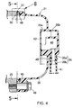
- a breather chamber 40 for performing gas liquid separation of the blow-by gas produced within the engine main body 21 is formed on the inside of the head cover 26.
- an outlet pipe 39 for leading out the blow-by gas form the breather chamber 40 An end of a hose 41 for introducing the blow-by gas to the air cleaner 29 side is joined to the outlet pipe 39.
- the head cover 26 is made of resin and the outlet pipe 39 is made also of resin.
- the breather chamber 40 is formed between the head cover 26 and a resin cover plate 42 welded to the head cover 26.
- Projecting integrally from an inner surface of the head cover 26 are a contour wall portion 26a which is configured to form an outer contour of the breather chamber 40, and labyrinth wall portions 26b which are arranged in multiple locations of a part surrounded by the contour wall portion 26a in such a way as to form a labyrinth passage in the breather chamber 40.
- the cover plate 42 is welded to the contour wall portion 26a and the labyrinth wall portions 26b.
- the blow-by gas is introduced into the breather chamber 40 as indicated by arrows in Fig. 5 .
- the blow-by gas after the gas liquid separation has been performed while passing through the labyrinth passage within the breather chamber 40 is led out of the outlet pipe 39.
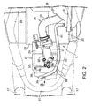
- the outlet pipe 39 is integrally formed with the head cover 26 in such a way as to be arranged above the cylinder axis C in communication with the breather chamber 40.
- the outlet pipe 39 is integrally formed with the head cover 26 such that it faces to one of the vehicle width direction (to the right in this embodiment) in a condition where the engine main body 21 is loaded on the motorcycle.
- the release device 43 which is configured to release the blow-by gas outwardly by separating the hose 41 from the outlet pipe 39 when the pressure of the blow-by gas within the engine main body 21 is not less than a predetermined pressure.
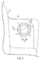
- the release device 43 includes a groove 44 which is formed in a part of an outer circumference of the outlet pipe 39 covered with an end portion of the hose 41 in such a way as to communicate with the breather chamber 40.
- the groove 44 is formed in an outer circumference of the outlet pipe 39, for example, in four places at regular intervals in the circumferential direction.
- the outlet pipe 39 is integrally provided with a cylinder section 39 a basal end portion of which is connected to an outer surface of the head cover 26 and an annular expanded section 39b which is expanded radially outwardly from a distal end portion of the cylinder section 39a.
- the groove 44 is formed on an outer circumference of the annular expanded section 39b. In addition, the groove 44 is recessed inwardly from an outer circumference of the cylinder section 39a.
- a clip 45 which is arranged on a closer side to the head cover 26 than the release device 43 is attached on an overlapping portion between the outlet pipe 39 and an end portion of the hose 41 which is connected to the outlet pipe 39 in a state of covering a part of the outlet pipe 39.
- the clip 45 is attached on the overlapping portion between the outlet pipe 39 and the end portion of the hose 41 in a part corresponding to the cylinder section 39a of the outlet pipe 39.
- the head cover 26 is connected to the cylinder head 25 by multiple bolts, for example, four bolts 4.
- a gasket 48 is held between the cylinder head 25 and the head cover 26 as clearly shown in Fig. 3 , the predetermined pressure at which the release device 43 releases the blow-by gas outwardly by separating the hose 41 from the outlet pipe 39 is set up at a lower level than the pressure of the blow-by gas within the engine main body 21 at the time the gasket 48 loses its function.
- a seal keeping critical pressure of the gasket 48 is 240kPa for example, whereas the predetermined pressure is 170kPa for example.
- the gasket 48 is located between a first connecting surface 50 which is formed in the head cover 26 in opposition to the cylinder head 25 and a second connecting surface 51 which is formed in the cylinder head 25 in opposition to the first connecting surface 50.
- the gasket 48 is held between the cylinder head 25 and the head cover 26 in such a manner that it is fitted in a fitting groove 49 formed in the first connecting surface 50 serving as one of the first and second connecting surfaces 50, 51 and makes sealing contact with the second connecting surface 51 serving as the other of the first and second connecting surfaces 50, 51.
- the fitting groove 49 is formed continuously in endless fashion around a full circumference of the head cover 26.
- Fig. 8 shows a condition where the gasket 48 is not compressed in the direction to be squeezed by the cylinder head 25 and the head cover 26, in order to make a shape of the gasket 48 clear.
- the gasket 48 is integrally provided with a fitting section 52 to be fitted in the fitting groove 49 in such a manner that an end portion of the fitting section 52 comes in contact with a closed end wall 49a of the fitting groove 49, and a flange section 53 which is continuous with the other end portion of the fitting section 52 and makes sealing contact with the second connecting surface 51.
- the fitting section 52 is formed in an annular shape so as to be fitted in the fitting groove 49. On inner and outer circumferences of the fitting section 52 there are integrally formed buckling preventing projections 54, 55 in projecting fashion.
- the flange section 53 is composed of an inner flange portion 53a which passes through a center in the width direction of the fitting section 52 and which extends from a phantom line VL which extends in parallel with the squeezing direction of the gasket 48, to inward sides of the cylinder head 25 and the head cover 26, and an outer flange portion 53b which extends from the phantom line VL to outward sides of the cylinder head 25 and the head cover 26.
- An extension length L1 of the inner flange portion 53a from the phantom line VL is set up larger than an extension length L2 of the outer flange portion 53b from the phantom line VL.
- a first inner sealing projection 56 projecting toward the second connecting surface 51.
- an outer sealing projection 57 projecting toward the second connecting surface 51.
- a distance L3 between the phantom line VL and the first inner sealing projection 56 is set up substantially equal to a distance L4 between the phantom line VL and the outer sealing projection 57.
- a distance from the first sealing projection 56 to a distal end of the inner flange portion 53a is set up larger than a distance from the outer sealing projection 57 to a distal end of the outer flange portion 53b.
- a second sealing projection 58 which projects toward the second connecting surface 51.
- a concave portion 59 which is recessed in the direction separated apart from the second connecting surface 51.
- the concave portion 59 is configured such that it is separated from the second connecting surface 51 even if the gasket 48 is compressed in the squeezing direction by tightening the bolts 46.
- the concave portion 59 is recessed deeper than a central concave portion 60 which is formed in the flange section 53 between the first inner sealing projection 56 and the outer sealing projection 57.
- the distal end portion of the inner flange portion 53a is located outwardly of the inner wall surfaces of the cylinder head 25 and the head cover 26 in a condition where the gasket 48 is held between the cylinder head 25 and the head cover 26 (including a condition of Fig. 8 and a condition where the gasket 48 is compressed in the squeezing direction by tightening the bolts 46).
- the breather chamber 40 for performing the gas liquid separation of the blow-by gas produced within the engine main body 21 is formed on the inside of the head cover 26.
- the outlet pipe 39 is provided in the head cover 26 so as to lead out the blow-by gas from the breather chamber 40.
- One end portion of the hose 41 which leads the blow-by gas to the air cleaner 29 side is connected to the outlet pipe 39.
- the release device 43 is provided in the outlet pipe 39 in order for releasing the blow-by gas to the outside by separating the hose 41 from the outlet pipe 39 when the pressure of the blow-by gas within the engine main body 21 is not less than the predetermined pressure.
- the blow-by gas can be forcibly released from the outlet pipe 39 to the outside on purpose.
- the blow-by gas after the gas liquid separation has been performed while passing through the breather chamber 40 is led out of the outlet pipe 39, the outward leakage of oil or the like can be prevented effectively and the influence upon the surrounding environment can be suppressed at a lower level.
- the engine main body 21 is mounted on the vehicle in a condition where the cylinder axis C of the engine main body 21 is forwardly inclined.
- the outlet pipe 39 is provided above the cylinder axis C in the head cover 26. Therefore, the gas liquid separation can be performed effectively. Even in the case where the blow-by gas is forcibly discharged from the outlet pipe 39 to the outside by the release device, the outward leakage of oil or the like can be prevented effectively and the influence upon the surrounding environment can be suppressed at a lower level.
- the predetermined pressure at which the release device 43 works in such a way as to forcibly release the blow-by gas from the outlet pipe 39 to the outside on purpose is set up at a lower level than the pressure of the blow-by gas within the engine main body 21 at the time the gasket 48 is held between the cylinder head 25 and the head cover 26 loses its function. Therefore, the release device 43 release the blow-by gas to the outside by separating the hose 41 from the outlet pipe 39, before the gasket 48 loses its function due to the increase in pressure within the engine main body 21, whereby it is possible to prevent the blow-by gas from coming out of the unexpected part which is poor in the sealing characteristic.
- the release device 43 includes the groove 44 which is in communication with the inside of the breather chamber 40 and which is formed in a part of the outer circumference of the outlet pipe 39 covered with the end portion of the hose 41. Therefore, the release device 43 can be easily formed, and the hose 41 can be expanded so as to be separated from the outlet pipe 39 by allowing the pressure of the blow-by gas introduced into the groove 44 to effectively act on the inner circumference of the hose 41.
- the outlet pipe 39 is integrally provided with the cylinder section 39a the basal end portion of which is connected to the outer surface of the head cover 26 and the annular expanded section 39b which is expanded radially outwardly from the distal end portion of the cylinder section 39a, and the groove 44 is formed on the outer circumference of the annular expanded section 39b. Therefore, the interference of the connecting portion of the hose 41 is ensured by the annular expanded section 39b, so that it is possible to restrain the decrease in the rigidity of the outlet pipe 39 by formation of the groove 44. In addition, since the groove 44 is recessed from the outer circumference of the cylinder section 39a, the blow-be gas can be easily introduced between the hose 41 and the outlet pipe 39.
- the clip 45 which is arranged on the closer side to the head cover 26 than the release device 43 is attached on the overlapping portion between the outlet pipe 39 and the end portion of the hose 41 which is connected to the outlet pipe 39 in a state of covering a part of the outlet pipe 39. Therefore, in the case where the end of the hose 41 is fixed on the outlet pipe 39 by the clip 45, the function of the release device 43 can be ensured in a condition where the clip 45 does not interfere with the release device 43.
- the head cover has the first connecting surface 50
- the cylinder head 25 has the second connecting surface 51.
- the gasket 48 is fitted in the fitting groove 49 formed in the first connecting surface 50 and held between the cylinder head 25 and the head cover 26.
- This gasket 48 is integrally comprised of the fitting section 52 to be fitted in the fitting groove 49 in such a manner that one end portion of the fitting section 52 comes in contact with the closed end wall 49a of the fitting groove 49, and the flange section 53 which has the inner flange portion 53a and the outer flange portion 53b and which is connected continuously with the other end portion of the fitting section 52 and makes sealing contact with the second connecting surface 51.
- the inner flange portion 53a passes through the center in the width direction of the fitting section 52 and extends from the phantom line VL which extends in parallel with the squeezing direction of the gasket 48, to the inward sides of the cylinder head 25 and the head cover 26, and the outer flange portion 53b extends from the phantom line VL to the outward sides of the cylinder head 25 and the head cover 26.
- the extension length L1 of the inner flange portion 53a from the phantom line VL is set up larger than the extension length L2 of the outer flange portion 53b from the phantom line VL.
- first inner sealing projection 56 projecting toward the second connecting surface 51 is provided in the inner flange portion 53a.
- the outer sealing projection 57 projecting toward the second connecting surface 51 is provided in the outer flange portion 53b.
- the distances L3, L4 between the phantom line VL and each of the first inner sealing projection 56 and the outer sealing section are set up substantially equally in a condition where the distance from the first sealing projection 56 to the distal end of the inner flange portion 53a is larger than the distance from the outer sealing projection 57 to the distal end of the outer flange portion 53b.
- the inner flange portion 53a is able to be bent flexibly due to the formation of the concave portion 59, so that the second inner sealing projection 58 can be easy to make sealing contact with the second connecting surface 51.
- a contact area of the inner flange portion 53a relative to the second connecting surface 51 is decreased so as to heighten the surface pressure whereby the sealing characteristic can be maintained in good condition.
- the concave portion 59 is recessed deeper than the central concave portion 60 which is formed in the flange section 53 between the first inner sealing projection 56 and the outer sealing projection 57. Therefore, the distal end part of the inner flange portion 53a is able to be bent more flexibly, so that the second inner sealing projection 58 easily makes closer contact with the second connecting surface 51.
- the space is easily formed between the first and second sealing projections 56, 58 in a condition where the gasket 48 is deformed outwardly, so that the contact area of the inner flange portion 53a relative to the second connecting surface 51 is decreased so as to heighten the surface pressure whereby the sealing characteristic can be maintained in good condition.
- the distal end portion of the inner flange portion 53a is located on the outside of the inner wall surfaces of the cylinder head 25 and the head cover 26 in a condition where the gasket 48 is held between the cylinder head 25 and the head cover 26. Therefore, the gasket 48 is not allowed to interfere with a valve gear system or the like within the engine main body 21, and there is no influence on the oil flow flowing along the inner wall surfaces of the head cover 25 and the cylinder head 26.
- the head cover 26 is made of resin, the head cover 26 and the engine main body 21can be lightened, and the sealing characteristic of the gasket 48 can be maintained effectively against the influence of deformation or the like of the resonated head cover 26.
- the outlet pipe 39 is formed integrally and continuously with the head cover 26, the formation of the release device 43 can be facilitated.
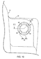
- the release device 61 While in the outlet pipe 39 which is formed integrally and continuously with the head cover 26 forming a part of the engine main body 21 there is provided a release device 61 which is configured to release the blow-by gas to the outside by separating the hose 41 from the outlet pipe 39 when the pressure of the blow-by gas within the engine main body 21 is not less than the predetermined pressure, the release device 61 in this embodiment includes a cutout 62 which is provided in a part of the outlet pipe 39 covered with one end portion of the hose 41 so as to provide communication between the inner side and the outer side of the outlet pipe 39.
- the cutout 62 is formed in the outlet pipe 39, for example, in four places at regular intervals in the circumferential direction.
- the release device 63 which is configured to release the blow-by gas to the outside by separating the hose 41 from the outlet pipe 39 when the pressure of the blow-by gas within the engine main body 21 is not less than the predetermined pressure.
- the release device 63 includes a through bore 64 which is provided in a part of the outlet pipe 39 covered with one end portion of the hose 41 so as to provide communication between the inner side and the outer side of the outlet pipe 39.
- the through bore 64 is formed in the outlet pipe 39, for example, in four places at regular intervals in the circumferential direction.
Landscapes
- Engineering & Computer Science (AREA)
- General Engineering & Computer Science (AREA)
- Mechanical Engineering (AREA)
- Chemical & Material Sciences (AREA)
- Combustion & Propulsion (AREA)
- Lubrication Details And Ventilation Of Internal Combustion Engines (AREA)
- Cylinder Crankcases Of Internal Combustion Engines (AREA)
Applications Claiming Priority (1)
| Application Number | Priority Date | Filing Date | Title |
|---|---|---|---|
| JP2014012226A JP6253145B2 (ja) | 2014-01-27 | 2014-01-27 | 内燃機関 |
Publications (1)
| Publication Number | Publication Date |
|---|---|
| EP2899378A1 true EP2899378A1 (fr) | 2015-07-29 |
Family
ID=52394936
Family Applications (1)
| Application Number | Title | Priority Date | Filing Date |
|---|---|---|---|
| EP15151895.8A Withdrawn EP2899378A1 (fr) | 2014-01-27 | 2015-01-21 | Moteur à combustion interne |
Country Status (3)
| Country | Link |
|---|---|
| EP (1) | EP2899378A1 (fr) |
| JP (1) | JP6253145B2 (fr) |
| IN (1) | IN2015DE00138A (fr) |
Cited By (1)
| Publication number | Priority date | Publication date | Assignee | Title |
|---|---|---|---|---|
| US20150096272A1 (en) * | 2013-10-09 | 2015-04-09 | Toyota Boshoku Kabushiki Kaisha | Oil separator for separating oil from blow-by gas of internal combustion engine |
Citations (6)
| Publication number | Priority date | Publication date | Assignee | Title |
|---|---|---|---|---|
| JPS60180707U (ja) * | 1984-05-10 | 1985-11-30 | ヤンマーディーゼル株式会社 | 汎用小形内燃機関のブリ−ザ装置 |
| JPH0237209U (fr) * | 1988-09-03 | 1990-03-12 | ||
| US6273074B1 (en) * | 1999-09-05 | 2001-08-14 | Honda Giken Kogyo Kabushiki Kaisha | Crankcase emission control system |
| JP3646066B2 (ja) | 2001-01-09 | 2005-05-11 | 本田技研工業株式会社 | エンジンの排気浄化用2次空気供給装置 |
| JP2005273562A (ja) * | 2004-03-25 | 2005-10-06 | Mazda Motor Corp | エンジンのブローバイガス還元装置 |
| EP2543834A1 (fr) * | 2011-07-03 | 2013-01-09 | Honda Motor Co., Ltd. | Structure de circuit de blow-by de moteur de motocyclette |
Family Cites Families (3)
| Publication number | Priority date | Publication date | Assignee | Title |
|---|---|---|---|---|
| JPS62145915U (fr) * | 1986-03-07 | 1987-09-14 | ||
| JPS6328815U (fr) * | 1986-08-08 | 1988-02-25 | ||
| JP2003232600A (ja) * | 2002-02-07 | 2003-08-22 | Denso Corp | 熱交換器のパイプ構造 |
-
2014
- 2014-01-27 JP JP2014012226A patent/JP6253145B2/ja not_active Expired - Fee Related
-
2015
- 2015-01-15 IN IN138DE2015 patent/IN2015DE00138A/en unknown
- 2015-01-21 EP EP15151895.8A patent/EP2899378A1/fr not_active Withdrawn
Patent Citations (6)
| Publication number | Priority date | Publication date | Assignee | Title |
|---|---|---|---|---|
| JPS60180707U (ja) * | 1984-05-10 | 1985-11-30 | ヤンマーディーゼル株式会社 | 汎用小形内燃機関のブリ−ザ装置 |
| JPH0237209U (fr) * | 1988-09-03 | 1990-03-12 | ||
| US6273074B1 (en) * | 1999-09-05 | 2001-08-14 | Honda Giken Kogyo Kabushiki Kaisha | Crankcase emission control system |
| JP3646066B2 (ja) | 2001-01-09 | 2005-05-11 | 本田技研工業株式会社 | エンジンの排気浄化用2次空気供給装置 |
| JP2005273562A (ja) * | 2004-03-25 | 2005-10-06 | Mazda Motor Corp | エンジンのブローバイガス還元装置 |
| EP2543834A1 (fr) * | 2011-07-03 | 2013-01-09 | Honda Motor Co., Ltd. | Structure de circuit de blow-by de moteur de motocyclette |
Cited By (2)
| Publication number | Priority date | Publication date | Assignee | Title |
|---|---|---|---|---|
| US20150096272A1 (en) * | 2013-10-09 | 2015-04-09 | Toyota Boshoku Kabushiki Kaisha | Oil separator for separating oil from blow-by gas of internal combustion engine |
| US9394856B2 (en) * | 2013-10-09 | 2016-07-19 | Toyota Boshoku Kabushiki Kaisha | Oil separator for separating oil from blow-by gas of internal combustion engine |
Also Published As
| Publication number | Publication date |
|---|---|
| JP2015140663A (ja) | 2015-08-03 |
| IN2015DE00138A (fr) | 2015-07-31 |
| JP6253145B2 (ja) | 2017-12-27 |
Similar Documents
| Publication | Publication Date | Title |
|---|---|---|
| US10294877B2 (en) | Straddle-type vehicle | |
| EP2463187B1 (fr) | Véhicule de type à enfourcher | |
| US10443459B2 (en) | Oil filter attaching structure for vehicle-mounted internal combustion engine | |
| EP2899434B1 (fr) | Structure de joint d'étanchéité d'un moteur à combustion interne | |
| JPWO2014097774A1 (ja) | エンジンの過給システム | |
| US9453441B2 (en) | Breather apparatus for internal combustion engine for vehicle | |
| EP3059407B1 (fr) | Silencieux d'échappement | |
| JP4341905B2 (ja) | スクータ型自動二輸車の吸気装置 | |
| US20150101558A1 (en) | Air intake system of saddle-ride type vehicle | |
| US20190316552A1 (en) | Injector arrangement structure | |
| JP2018162760A (ja) | 吸気通路構造 | |
| JP2014181678A (ja) | 鞍乗型車両の内燃機関 | |
| EP3069972A1 (fr) | Vehicule a monture de selle | |
| US8776924B2 (en) | Intake system for saddle-ride type vehicle | |
| JP2017180244A (ja) | 鞍乗り型車両 | |
| JP6253145B2 (ja) | 内燃機関 | |
| US11408313B2 (en) | Exhaust device for internal combustion engine of saddled vehicle | |
| JP6524135B2 (ja) | 鞍乗り型車両用内燃機関における排気ガスセンサー配設構造 | |
| US20120247409A1 (en) | Structure for discharging water from cooling water pump in vehicle engine | |
| JP2010084640A (ja) | 内燃機関のインテークマニホールド | |
| US9631527B2 (en) | Exhaust system | |
| US8348013B2 (en) | Exhaust device of internal combustion engine | |
| US9206763B2 (en) | Engine and straddle-type vehicle | |
| JP6319012B2 (ja) | エンジンのブリーザ室レイアウト構造 | |
| JP6446206B2 (ja) | 乗物のカバー構造 |
Legal Events
| Date | Code | Title | Description |
|---|---|---|---|
| PUAI | Public reference made under article 153(3) epc to a published international application that has entered the european phase |
Free format text: ORIGINAL CODE: 0009012 |
|
| 17P | Request for examination filed |
Effective date: 20150121 |
|
| AK | Designated contracting states |
Kind code of ref document: A1 Designated state(s): AL AT BE BG CH CY CZ DE DK EE ES FI FR GB GR HR HU IE IS IT LI LT LU LV MC MK MT NL NO PL PT RO RS SE SI SK SM TR |
|
| AX | Request for extension of the european patent |
Extension state: BA ME |
|
| 17P | Request for examination filed |
Effective date: 20160128 |
|
| RBV | Designated contracting states (corrected) |
Designated state(s): AL AT BE BG CH CY CZ DE DK EE ES FI FR GB GR HR HU IE IS IT LI LT LU LV MC MK MT NL NO PL PT RO RS SE SI SK SM TR |
|
| 17Q | First examination report despatched |
Effective date: 20190301 |
|
| GRAP | Despatch of communication of intention to grant a patent |
Free format text: ORIGINAL CODE: EPIDOSNIGR1 |
|
| RIC1 | Information provided on ipc code assigned before grant |
Ipc: F01M 13/02 20060101AFI20191128BHEP Ipc: F16N 21/00 20060101ALI20191128BHEP Ipc: F02M 35/10 20060101ALN20191128BHEP Ipc: F16L 33/02 20060101ALI20191128BHEP |
|
| INTG | Intention to grant announced |
Effective date: 20191216 |
|
| STAA | Information on the status of an ep patent application or granted ep patent |
Free format text: STATUS: THE APPLICATION IS DEEMED TO BE WITHDRAWN |
|
| 18D | Application deemed to be withdrawn |
Effective date: 20200603 |