EP2899450B1 - Appareil d'éclairage à DEL - Google Patents
Appareil d'éclairage à DEL Download PDFInfo
- Publication number
- EP2899450B1 EP2899450B1 EP14200181.7A EP14200181A EP2899450B1 EP 2899450 B1 EP2899450 B1 EP 2899450B1 EP 14200181 A EP14200181 A EP 14200181A EP 2899450 B1 EP2899450 B1 EP 2899450B1
- Authority
- EP
- European Patent Office
- Prior art keywords
- heat
- dissipating
- lighting apparatus
- core
- led lighting
- Prior art date
- Legal status (The legal status is an assumption and is not a legal conclusion. Google has not performed a legal analysis and makes no representation as to the accuracy of the status listed.)
- Active
Links
Images



Classifications
-
- F—MECHANICAL ENGINEERING; LIGHTING; HEATING; WEAPONS; BLASTING
- F21—LIGHTING
- F21V—FUNCTIONAL FEATURES OR DETAILS OF LIGHTING DEVICES OR SYSTEMS THEREOF; STRUCTURAL COMBINATIONS OF LIGHTING DEVICES WITH OTHER ARTICLES, NOT OTHERWISE PROVIDED FOR
- F21V29/00—Protecting lighting devices from thermal damage; Cooling or heating arrangements specially adapted for lighting devices or systems
- F21V29/50—Cooling arrangements
- F21V29/70—Cooling arrangements characterised by passive heat-dissipating elements, e.g. heat-sinks
-
- F—MECHANICAL ENGINEERING; LIGHTING; HEATING; WEAPONS; BLASTING
- F21—LIGHTING
- F21K—NON-ELECTRIC LIGHT SOURCES USING LUMINESCENCE; LIGHT SOURCES USING ELECTROCHEMILUMINESCENCE; LIGHT SOURCES USING CHARGES OF COMBUSTIBLE MATERIAL; LIGHT SOURCES USING SEMICONDUCTOR DEVICES AS LIGHT-GENERATING ELEMENTS; LIGHT SOURCES NOT OTHERWISE PROVIDED FOR
- F21K9/00—Light sources using semiconductor devices as light-generating elements, e.g. using light-emitting diodes [LED] or lasers
- F21K9/20—Light sources comprising attachment means
- F21K9/23—Retrofit light sources for lighting devices with a single fitting for each light source, e.g. for substitution of incandescent lamps with bayonet or threaded fittings
- F21K9/233—Retrofit light sources for lighting devices with a single fitting for each light source, e.g. for substitution of incandescent lamps with bayonet or threaded fittings specially adapted for generating a spot light distribution, e.g. for substitution of reflector lamps
-
- F—MECHANICAL ENGINEERING; LIGHTING; HEATING; WEAPONS; BLASTING
- F21—LIGHTING
- F21V—FUNCTIONAL FEATURES OR DETAILS OF LIGHTING DEVICES OR SYSTEMS THEREOF; STRUCTURAL COMBINATIONS OF LIGHTING DEVICES WITH OTHER ARTICLES, NOT OTHERWISE PROVIDED FOR
- F21V29/00—Protecting lighting devices from thermal damage; Cooling or heating arrangements specially adapted for lighting devices or systems
- F21V29/50—Cooling arrangements
- F21V29/70—Cooling arrangements characterised by passive heat-dissipating elements, e.g. heat-sinks
- F21V29/74—Cooling arrangements characterised by passive heat-dissipating elements, e.g. heat-sinks with fins or blades
- F21V29/77—Cooling arrangements characterised by passive heat-dissipating elements, e.g. heat-sinks with fins or blades with essentially identical diverging planar fins or blades, e.g. with fan-like or star-like cross-section
- F21V29/773—Cooling arrangements characterised by passive heat-dissipating elements, e.g. heat-sinks with fins or blades with essentially identical diverging planar fins or blades, e.g. with fan-like or star-like cross-section the planes containing the fins or blades having the direction of the light emitting axis
-
- F—MECHANICAL ENGINEERING; LIGHTING; HEATING; WEAPONS; BLASTING
- F21—LIGHTING
- F21V—FUNCTIONAL FEATURES OR DETAILS OF LIGHTING DEVICES OR SYSTEMS THEREOF; STRUCTURAL COMBINATIONS OF LIGHTING DEVICES WITH OTHER ARTICLES, NOT OTHERWISE PROVIDED FOR
- F21V29/00—Protecting lighting devices from thermal damage; Cooling or heating arrangements specially adapted for lighting devices or systems
- F21V29/50—Cooling arrangements
- F21V29/70—Cooling arrangements characterised by passive heat-dissipating elements, e.g. heat-sinks
- F21V29/83—Cooling arrangements characterised by passive heat-dissipating elements, e.g. heat-sinks the elements having apertures, ducts or channels, e.g. heat radiation holes
-
- F—MECHANICAL ENGINEERING; LIGHTING; HEATING; WEAPONS; BLASTING
- F21—LIGHTING
- F21Y—INDEXING SCHEME ASSOCIATED WITH SUBCLASSES F21K, F21L, F21S and F21V, RELATING TO THE FORM OR THE KIND OF THE LIGHT SOURCES OR OF THE COLOUR OF THE LIGHT EMITTED
- F21Y2115/00—Light-generating elements of semiconductor light sources
- F21Y2115/10—Light-emitting diodes [LED]
Definitions
- One or more embodiments of the disclosure relate to a light emitting diode (LED) lighting apparatus including a heat-dissipating member, and more particularly, to an LED lighting apparatus including a heat-dissipating member accommodated in an exterior member.
- LED light emitting diode
- LEDs are semiconductor devices capable of emitting light by the electroluminescence phenomenon when a forward voltage is applied thereto.
- the emission wavelength of LEDs may be determined by semiconductor crystal materials and concentrations thereof.
- LEDs may generate ultraviolet rays, visible rays, or infrared rays.
- LED lighting apparatuses consume low power and have fast responses, as compared with other lighting apparatuses such as fluorescent lamps, halogen lamps, and incandescent lamps. In addition, LEDs are eco-friendly and efficient. Therefore, much research has been conducted to commercialize LED lighting apparatuses.
- heat-dissipating members are exposed to the outside of lighting apparatuses to dissipate heat through direct contact with ambient air.
- surfaces of the heat-dissipating members may be covered with contaminants such as dust, and thus, the heat-dissipating ability of the heat-dissipating members may be lowered due to the contaminants.
- outdoor LED lighting apparatuses may have a short lifespan and low brightness in spite of the semi-permanent characteristics of LEDs.
- exposed heat-dissipating members may decrease the degree of design freedom of LED lighting apparatuses and may make it difficult to provide effective waterproofing.
- US2007/132092 discloses an LED assembly which includes a packaged LED module and a heat dissipation device.
- EP2175196 discloses a heat dissipation member having variable heat dissipation paths and an LED lighting flood lamp using the heat dissipation member.
- One or more embodiments of the disclosure include a light-emitting diode (LED) lighting apparatus having increased degrees of design freedom.
- LED light-emitting diode
- One or more embodiments of the disclosure include a waterproof and dustproof LED lighting apparatus.
- an LED lighting apparatus includes an LED board on which an LED module is disposed, a heat-dissipating member, an exterior member, and a cover unit.
- the heat-dissipating member includes a mount on which the LED board is disposed, a core connected to the mount, and a heat-dissipating part.
- the heat-dissipating part includes a plurality of concave and convex portions repeatedly arranged around the core in radial directions of the core and extending in a length direction of the core.
- the exterior member includes an, optionally cylindrical, main body inserted in the core and an outer part extending from an upper edge of the main body to accommodate the concave and convex portions therein, a side of the outer part having an opening.
- the cover unit is coupled to the side of the outer part of the exterior member to seal the opening.
- the outer part may include a first surface facing the concave and convex portions of the heat-dissipating part, and a second surface facing an outer side, wherein concave and convex portions may be repeatedly formed on the first surface of the outer part.
- the outer part may include a first surface facing the concave and convex portions, and a second surface facing an outer side, wherein bosses may be repeatedly formed on the first surface of the outer part.
- the concave and convex portions of the heat-dissipating part may include a first peripheral portion, a second peripheral portion, and a connection portion connecting the first and second peripheral portions, and the first and second peripheral portions may extend in a circumferential direction of the core, wherein concave and convex portions may be repeatedly formed on at least one surface of the first and second peripheral portions.
- the LED lighting apparatus further includes, in accordance with the invention, a medium having a greater conductivity than that of air which is disposed between the heat-dissipating member and the exterior member member, wherein the LED lighting apparatus is airtight so as to prevent ambient air from permeating into the LED lighting apparatus.
- the heat-dissipating member and the exterior member may be formed of aluminum, copper, and/or tungsten.
- an LED lighting apparatus includes an LED board on which an LED module is disposed, a heat-dissipating member, an exterior member, and a cover unit.
- the heat-dissipating member includes a mount on which the LED board is disposed, a core connected to the mount, and a plurality of heat-dissipating fins extending from the core, the heat dissipating fins being spaced from one another.
- the plurality of heat-dissipating fins may be ring-shaped heat-dissipating fins extending in a circumferential direction of the core, the heat-dissipating fins being spaced apart from each other in a length direction of the core.
- the plurality of heat-dissipating fins may extend in a lengthwise direction of the core, the heat-dissipating fins being spaced apart from each other in a circumferential direction of the core.
- the exterior member includes an, optionally cylindrical, main body inserted in the core and an outer part extending from an upper edge of the main body to accommodate the heat-dissipating fins therein, a side of the outer part being opened.
- the cover unit is coupled to the side of the outer part of the exterior member to seal the opening.
- the outer part may include a first surface facing the heat-dissipating fins, and a second surface facing an outer side, wherein concave and convex portions may be repeatedly formed on the first surface of the outer part.
- the outer part may include a first surface facing the heat-dissipating fins, and a second surface facing an outer side, wherein bosses may be repeatedly formed on the first surface of the outer part.
- Each of the heat-dissipating fins includes a first surface and a second surface opposite to the first surface, wherein concave and convex portions are repeatedly formed on at least one of the first and second surfaces.
- a medium is disposed in a sealed space provided between the heat-dissipating member and the exterior member, the medium having a greater conductivity than that of air,wherein the LED lighting apparatus is airtight so as to prevent ambient air from permeating into the LED lighting apparatus.
- the heat-dissipating fins may have a rectangular plate shape.
- the LED lighting apparatus since the LED lighting apparatus includes the heat-dissipating member and the exterior member, the LED lighting apparatus may have improved heat dissipation efficiency. In addition, since the heat-dissipating member is not exposed to the outside, the LED lighting apparatus may have an increased degree of design freedom and may be dustproof and waterproof.
- FIG. 1 is a perspective view illustrating a light-emitting diode (LED) lighting apparatus 10 according to an embodiment of the disclosure
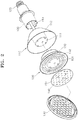
- FIG. 2 is an exploded perspective view illustrating the LED lighting apparatus 10 according to an embodiment of the disclosure.
- LED light-emitting diode
- the LED lighting apparatus 10 may include a housing 100, an exterior member 110, a heat-dissipating member 130, LED modules 150, a socket 120, a cover unit 190, and a cover portion 197.
- the housing 100 may have a cylindrical shape with a first end and a second end, which are both opened.
- the socket 120 may be coupled to an end of the housing 100.
- the first end of the housing 100 may correspond to the end closest to the socket 120, while the second end of the housing 100 may correspond to the end furthest from the socket 120.
- the second end of the housing 100 may be adjacent to, and connected to, exterior member 110.
- the housing 100 may be disposed in a main body 111 of the exterior member 110, and a connection member 160 may be disposed in the housing 100.
- the main body 111 may have a cylindrical shape, however the disclosure is not limited to this shape and the main body may be shaped in a rectangular, square, or other geometric manner.
- the exterior member 110 may include the main body 111 having the cylindrical shape and an outer part 112 configured to cover the heat-dissipating member 130.
- the housing 100 and the connection member 160 which is configured to connect a printed circuit board to the socket 120, may be disposed in the main body 111.
- the heat-dissipating member 130 may be disposed in the outer part 112 of the exterior member 110. That is, the heat-dissipating member 130 may be shaped such that a core 132 fits over main body 111, and the heat-dissipating member 130 resides or is disposed within the surrounding recess or interior space of the exterior member 110 about the main body 111.
- the main body 111 may have a cylindrical shape having a first end which is closed and an opposite second end which is opened. The closed first end may be inserted into an opened end of the core 132. Therefore, the heat-dissipating member 130 may not be seen from the outside and may be protected from dust and moisture.
- the LED lighting apparatus 10 since the LED lighting apparatus 10 includes the exterior member 110, the degree of design freedom of the LED lighting apparatus 10 may be increased by freely selecting the outer surface shape of the outer part 112.
- the outer surface shape of the outer part 112 as shown in FIG. 2 is shaped in a conical fashion, resembling a lampshade, or more particularly, a truncated cone or the frustum of a cone.
- the disclosure is not limited to this example surface shape of the outer part 112, which may take other shapes.
- the surface shape of the outer part 112 may be spherical, rectangular, triangular, or shaped in other polygonal or geometric shapes, which may or may not be symmetric, irregular, or truncated.
- the outer part 112 may have any other shape capable of accommodating the heat-dissipating part 133.
- the LED modules 150 may be coupled to an LED board 151, on which the printed circuit board is mounted, and in this state, the LED modules 150 may be disposed on an end of the exterior member 110.
- the LED modules 150 may be manufactured by mounting LEDs on a package substrate and packaging the LEDs.
- the LED board 151, on which the LED modules 150 are mounted, may be mounted on a mount 131 of the heat-dissipating member 130 by using additional fastening members.
- the LED modules 150 may be arranged on the LED board 151 in any number of ways or patterns. Generally, the LED modules 150 may be arranged on the LED board 151 according to a desired output or performance of the LED modules 150.
- the socket 120 may be coupled to an end of the housing 100 and may be electrically connected to the printed circuit board (not shown) mounted on the LED board 151 through the connection member 160 disposed in the housing 100.
- the socket 120 may have an Edison type structure or a swan type structure.
- the cover unit 190 may be coupled to the exterior member 110 to cover the LED modules 150.
- a cover portion 197 of the cover unit 190 protects the LED modules 150 and transmits light emitted from the LED modules 150.
- the cover portion 197 may have a semispherical (e.g., lens) shape or a plate (e.g., planar) shape having a predetermined thickness.
- the disclosure is not limited to these example shapes of the cover portion 197.
- the cover portion 197 is shaped in a similar manner as the cover unit 190, which may also take various forms or shapes. That is, a shape of the cover unit 190 may correspond to the surface shape of outer part 112 of the exterior member 110.
- the cover unit 190 may be coupled to the exterior member 110 using various fastening devices or locking or sealing mechanisms (e.g., screws, clips, via an O-ring, etc.).
- the heat-dissipating member 130 may include the mount 131 coupled to the LED board 151, a core 132 having a barrel shape such as a cylindrical shape having an opened end and an opposite closed end, and a heat-dissipating part 133 connected to the core 132.
- the core 132 may have an opened end which is adjacent to an end of main body 111, and a closed end which is adjacent to mount 131 and LED board 151. Heat generated while the LED modules 150 are powered may be sequentially transferred to the LED board 151, the mount 131, the core 132, and the heat-dissipating part 133.
- a medium 200 (refer to FIG.
- the rate of heat transfer from the heat-dissipating part 133 to the exterior member 110 may be increased. That is, since the rate of heat conduction between media increases as the contact area between the media increases, the efficiency of heat dissipation may be increased by increasing the contact area between the medium 200 and the heat-dissipating part 133 and/or the exterior member 110.
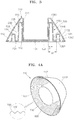
- FIG. 3 is a cross-sectional view illustrating the heat-dissipating member 130 and the exterior member 110 according to an embodiment of the disclosure.
- the heat-dissipating member 130 may be formed of a material having a high thermal conductivity such as aluminum. As shown in FIGS. 3 and 4C , the heat-dissipating member 130 may include the mount 131, the core 132, and the heat-dissipating part 133. The mount 131 may have a plate shape and be formed on a lower side of the heat-dissipating member 130 for coupling with the LED board 151.
- the mount 131 may have a plate shape and be formed on a lower side of the heat-dissipating member 130 for coupling with the LED board 151.
- the "lower side” may refer to a side of the heat-dissipating member 130 which is closer to the LED board 151, while the “upper side” may refer to a side of the heat-dissipating member 130 which is closer to the housing 100 or socket 120.
- the core 132 may have a cylindrical shape with a first end which is closed, and a second end which is open, or alternatively the core 132 may have a first end and a second end, which are both opened.
- an end of the core 132 e.g., a first end
- an end of the core 132 may be connected to the mount 131.
- an end of the core 132 e.g., a second end
- the heat-dissipating part 133 may include a plurality of peripheral portions 135 having a first end and a second end which are both opened, and ring-shaped connection portions 136 connecting upper or lower edges of the peripheral portions 135.
- the peripheral portions 135 may be arranged at preset intervals away from the core 132.
- the peripheral portions 135 may include a first peripheral portion 1351 closest to the core 132 and spaced a first distance di from the core 132, and a second peripheral portion 1352 that is second (or next) closest to the core 132 and spaced a second distance d2 from the core 132.
- the peripheral portions 135 may further include a third peripheral portion 1353 which is furthest from the core 132 compared to the first peripheral portion 1351 and the second peripheral portion 1352.
- the third peripheral portion 1353 may be spaced apart from the core by a third distance.
- connection portions 136 may include a first connection portion 1361 disposed between upper edges of the core 132 and the first peripheral portion 1351 to connect the core 132 and the first peripheral portion 1351, and a second connection portion 1362 disposed between lower edges of the first and second peripheral portions 1351 and 1352 to connect the first and second peripheral portions 1351 and 1352.
- the connection portions 136 may further include a third connection portion which is disposed between upper edges of the second peripheral portion 1352 and third peripheral portion 1353 to connect the second and third peripheral portions 1352 and 1353. Therefore, as shown in FIG. 3 , concave portions 231 and convex portions 230 may be formed on the cross-section of the heat-dissipating part 133.
- the concave portions 231 and the convex portions 230 may be repeatedly arranged in radial directions of the core 132 and may extend in the length direction of the core 132 by repeatedly arranging the peripheral portions 135 and connecting neighboring pairs of the peripheral portions 135 using the connection portions 136. Since the concave portions 231 and the convex portions 230 are formed on the heat-dissipating part 133, the heat-dissipating part 133 may have a large surface area.
- the contact area between the heat-dissipating part 133 and the medium 200 filled between the heat-dissipating member 130 and the exterior member 110 may be increased, and thus, heat may be efficiently transferred from the heat-dissipating member 130 to the medium 200.
- the medium 200 may correspond to an intermediate material for transferring heat from the heat-dissipating member 130 to the exterior member 110.
- a gaseous material may be used as the medium 200.
- the LED lighting apparatus 10 shown in FIGS. 1 to 6B according to embodiments of the disclosure is, in accordance with the invention, airtight, and thus ambient air cannot permeate into the LED lighting apparatus 10.
- a gas having a higher thermal conductivity than that of air may be filled between the heat-dissipating member 130 and the exterior member 110 to effectively transfer heat.
- the exterior member 110 may correspond to a shield which protects the heat-dissipating member 130 from surrounding environments. Owing to the exterior member 110, the heat-dissipating member 130 may not be seen from the outside of the LED lighting apparatus 10 and may be protected from dust and moisture.
- the exterior member 110 may include the main body 111 and the outer part 112.
- the main body 111 may have a cylindrical shape having a first end which is closed and an opposite second end which is opened.
- the main body 111 may be insertable into the core 132.
- the outer part 112 may be used to cover the heat-dissipating member 130.
- the outer part 112 may have a truncated cone shape with both end edges thereof being connected to an upper edge of the main body 111 and the circumference (i.e., circumferential outer portion) of the cover unit 190.
- An accommodation space may be formed in the outer part 112 to accommodate the heat-dissipating part 133.
- the shape of the outer part 112 is not limited to the truncated cone shape. That is, the outer part 112 may have any other shape capable of accommodating the heat-dissipating part 133.
- the exterior member 110 may have a first surface 1121 which makes contact with the medium 200 and a second surface 1122 making contact with ambient air, and thus, heat may be transferred to the outside of the exterior member 110.
- the first surface 1121 may correspond to an internal or interior surface of the outer part 112, while the second surface 1122 may correspond to an external or exterior surface of the outer part 112.
- the exterior member 110 may be formed of a material having a high thermal conductivity such as aluminum, copper, and tungsten.
- the cover unit 190 may be coupled to a lower side of the outer part 112 of the exterior member 110 with an O-ring (not shown) being disposed along the edge of an opened end of the outer part 112 of the exterior member 110, so as to close the inner space of the exterior member 110. In this way, the inner side of the exterior member 110 may be protected from dust and moisture.
- the cover unit 190 may be coupled to the outer part 112 of the exterior member 110 by other methods (e.g., a fastener such as a screw or clip), and the disclosure is not limited to coupling the cover unit 190 to the outer part 112 of the exterior member 110 via an O-ring.
- a fastener such as a screw or clip
- FIGS. 4A and 4B are perspective views illustrating modification examples of the exterior member 110.
- FIG. 4C is a perspective view illustrating a modification example of the heat-dissipating member 130.
- Heat may be transferred from the heat-dissipating member 130 to the outside by conduction, and thus, the effect of heat dissipation may be increased as the contact areas among the medium 200, the heat-dissipating part 133, and the exterior member 110 are increased.
- methods of increasing the surface areas of the heat-dissipating part 133 and the exterior member 110 making contact with the medium 200 will be explained with reference to FIGS. 4A to 4C .
- the outer part 112 of the exterior member 110 has a first surface 1121 making contact with the medium 200 and a second surface 1122 making contact with ambient air.
- a user may see the second surface 1122 of the outer part 112 from the outside of the exterior member 110.
- the second surface 1122 may be formed, for example, as an aesthetically-pleasing, dustproof, and waterproof surface.
- the second surface 1122 may be sleekly formed to improve the aesthetic appearance of the LED lighting apparatus 10 and prevent contaminants such as dust from accumulating thereon. Thus, a progressive decrease in the efficiency of heat dissipation caused by contaminants may be reduced.
- Concave portions 800 and convex portions 700 may be formed in the circumferential direction of the first surface 1121 to increase the rate of heat conduction. If the first surface 1121 of FIG. 4A , on which the concave portions 800 and the convex portions 700 are formed, is compared with the first surface 1121 shown in FIG. 3 , the first surface 1121 shown in FIG. 4A may have a larger surface area than the first surface 1121 shown in FIG. 3 owing to the concave portions 800 and the convex portions 700. That is, the first surface 1121 of FIG. 4A may have a larger specific surface area than the first surface 1121 of FIG. 3 . Thus, the contact area between the medium 200 and the first surface 1121 may be increased to increase the rate of heat conduction from the medium 200 to the exterior member 110.
- bosses 600 are repeatedly formed on the first surface 1121 of the outer part 112. If the first surface 1121 of FIG. 4B , on which the bosses 600 are formed, as shown in FIG. 4B , is compared with the first surface 1121 of FIG. 3 , on which no bosses are formed, the first surface 1121 shown in FIG. 4B may have a larger surface area than the first surface 1121 shown in FIG. 3 . Thus, the contact area between the medium 200 and the first surface 1121 may be increased to increase the rate of heat conduction.
- concave portions 1331 and convex portions 1332 are repeatedly formed on the first to third peripheral portions 1351, 1352, and 1353 of the peripheral portions 135 of the heat-dissipating part 133 in the circumferential directions thereof. If the peripheral portions 135 of FIG. 4C , on which the concave portions 1331 and the convex portions 1332 are formed, are compared with the peripheral portions 135 of FIG. 3 , on which the concave portions 1331 and the convex portions 1332 are not formed, the peripheral portions 135 shown in FIG.
- the peripheral portions 135 shown in FIG. 4C may have a larger surface area than the peripheral portions 135 shown in FIG. 3 owing to the concave portions 1331 and the convex portions 1332. That is, the peripheral portions 135 shown in FIG. 4C may have a larger specific surface area than the peripheral portions 135 shown in FIG. 3 .
- the contact area between the medium 200 and the peripheral portions 135 may be increased, and thus, the rate of heat conduction from the heat-dissipating part 133 to the medium 200 may be increased. In this way, the rate of heat conduction from the heat-dissipating part 133 to the medium 200 and the rate of heat conduction from the medium 200 to the exterior member 110 may be increased to increase the efficiency of heat dissipation of the LED lighting apparatus 10.
- FIG. 5A is a perspective view illustrating a heat-dissipating member 130 according to another embodiment of the disclosure.
- a heat-dissipating part 133 may include a plurality of heat-dissipating fins 140.
- first, second, and third heat-dissipating fins 1401, 1402, and 1403 may be arranged in the length direction of a core 132 and may be connected to the core 132.
- the first, second, and third heat-dissipating fins 1401, 1402, and 1403 may be formed to have a ring or disc shape, with the same or varying diameters.
- the first, second, and third heat-dissipating fins 1401, 1402, and 1403 may be arranged at regular or irregular intervals along the length direction of the core 132.
- the first, second, and third heat-dissipating fins 1401, 1402, and 1403 may extend the full length of the core 132, or only partially.
- the first, second, and third heat-dissipating fins 1401, 1402, and 1403 of the heat-dissipating part 133 may be arranged in parallel with each other and connected to the core 132. Then, both first and second surfaces 140a and 140b of the first, second, and third heat-dissipating fins 1401, 1402, and 1403 may be opened.
- the heat-dissipating fins 140 of the heat-dissipating part 133 may make contact with the medium 200 through both surfaces 140a and 140b of the heat-dissipating fins 140, and thus, the contact area therebetween may be increased to increase the rate of heat conduction by the heat-dissipating member 130.
- the disclosure is not limited to the example heat-dissipating part 133 shown in FIG. 5A .
- the heat-dissipating part 133 may include a plurality of heat-dissipating fins 140 (for example, two heat-dissipating fins, three heat-dissipating fins, or more than three heat-dissipating fins).
- FIG. 6A is a perspective view illustrating a heat-dissipating member 130 according to another embodiment of the disclosure.
- a heat-dissipating part 133 may include a plurality of heat-dissipating fins 170 having a rectangular plate shape and extending in the length direction of a core 132.
- the shape of the heat-dissipating fins 170 is not limited to a rectangular shape. That is, the heat-dissipating fins 170 may have any other shape as long as the heat-dissipating fins 170 may be disposed in the exterior member 110 and extend in the length direction of the core 132.
- the heat-dissipating fins 170 may be arranged at regular or irregular intervals along the circumferential direction of the core 132.
- the heat-dissipating fins 170 may extend the full length of the core 132, or only partially. For example, both first and second surfaces 170a and 170b of the heat-dissipating fins 170 may be opened and thus may make contact with the medium 200. Therefore, the contact area between the heat-dissipating part 133 and the medium 200 may be increased, and thus, the rate of heat conduction by the heat-dissipating member 130 may be increased.
- FIGS. 5B and 6B illustrate modified examples of the heat-dissipating member 130 of the LED lighting apparatus 10 of the embodiments shown in FIGS. 5A and 6A .
- heat may be transferred from the heat-dissipating member 130 to the outside by conduction, and thus, the effect of heat dissipation may be increased as the contact areas among the medium 200, the heat-dissipating part 133, and the exterior member 110 are increased.
- methods of increasing the surface area of the heat-dissipating part 133 making contact with the medium 200 will be explained with reference to FIGS. 5A to 6B .
- concave portions 1331 and convex portions 1332 are formed on the heat-dissipating fins 140 and 170. If the heat-dissipating fins 140 and 170 of FIGS. 5B and 6B , on which the concave portions 1331 and the convex portions 1332 are formed, are compared with the heat-dissipating fins 140 and 170 of FIGS. 5A and 6A , on which the concave portions 1331 and the convex portions 1332 are not formed, the heat-dissipating fins 140 and 170 shown in FIGS. 5B and 6B may have larger specific surface areas.
- the contact area with the medium 200 may be increased, and thus, the rate of heat conduction from the heat-dissipating part 133 to the medium 200 may be increased.
- the rate of heat conduction from the heat-dissipating part 133 to the medium 200, and the rate of heat conduction from the medium 200 to the outer part 112 of the exterior member 110 may be increased to increase the efficiency of heat dissipation of the LED lighting apparatus 10.
- FIGS. 7A and 7B are views illustrating an alternative, non-inventive LED lighting apparatus 10 allowing ambient air to pass therethrough to dissipate heat, according to embodiments of the disclosure.
- FIG. 7C is a cross-sectional view illustrating a heat-dissipating member and an exterior member having a modified surface structure according to another non-inventive illustrative example of the disclosure.
- a plurality of first penetration holes 191 may be formed along the circumference (e.g., the outer circumference) of a cover unit 190, and a plurality of second penetration holes 192 may be formed along an outermost connection portion 136 of a heat-dissipating part 133.
- a plurality of third penetration holes 193 may be formed along an upper circumference of an exterior member 110.
- the cover unit 190 may be coupled to a heat-dissipating member 130 so that the first penetration holes 191 may communicate with the second penetration holes 192, and thus ambient air 400 introduced into the LED lighting apparatus 10 through the first penetration holes 191 may flow through the second penetration holes 192.
- the ambient air 400 flows in a space formed between the heat-dissipating part 133 and a first surface 1121 of the exterior member 110, and then the ambient air 400 flows to the outside of the LED lighting apparatus 10 through the third penetration holes 193 formed in an upper side of the exterior member 110. That is, even after the LED lighting apparatus 10 is assembled, ambient air 400 may flow into the LED lighting apparatus 10 and may dissipate heat while flowing rapidly in a space formed between the heat-dissipating member 130 and the exterior member 110.
- the plurality of first penetration holes 191 may be formed along the circumference (e.g., the outer circumference) of the cover unit 190 at regular or irregular intervals, and may be any shape (for example, rectangular, square, circular, triangular, or any polygonal or geometric shape).
- the plurality of first penetration holes 191 may all be the same shape or have different shapes.
- the plurality of second penetration holes 192 may be formed along an outermost connection portion 136 of the heat-dissipating part 133 at positions which correspond to or align with the positions of the plurality of first penetration holes 191.
- the plurality of second penetration holes 192 may be the same shape or different shape of the corresponding first penetration holes 191.
- the plurality of second penetration holes 192 may all have the same shape as one another or have different shapes.
- the plurality of third penetration holes 193 may be formed along an upper circumference of an exterior member 110 and may be the same, less, or greater in number than the number of first penetration holes 191 and/or second penetration holes 192.
- the plurality of third penetration holes 193 may be the same shape or different shape of the first penetration holes 191 and/or second penetration holes 192.
- the plurality of third penetration holes 193 may all have the same shape as one another or have different shapes.
- heat may be transferred from the heat-dissipating member 130 to ambient air 400 by thermal conduction. Therefore, as the surface area of the heat-dissipating member 130 is increased, the effect of heat dissipation may be increased.
- a method of increasing the surface area of the heat-dissipating part 130 making contact with ambient air 400 will be explained with reference to FIG. 7C .
- concave portions 1331 and convex portions 1332 are repeatedly formed on an outermost peripheral portion 1355 of the heat-dissipating part 133, and concave portions 800 and convex portions 700 are repeatedly formed on the first surface 1121 of the exterior member 110.
- the outermost peripheral portion 1355 may have a large specific surface area, and thus, the contact area between the outermost peripheral portion 1355 and ambient air 400 may be increased. Therefore, the rate of heat conduction from the heat-dissipating part 133 to ambient air 400 may be increased, and thus, the efficiency of heat dissipation of the LED lighting apparatus 10 may, in this non-inventive example, be increased.
- an LED lighting apparatus may include a heat-dissipating member which is disposed entirely within an exterior member, such that the LED lighting apparatus has an improved heat dissipation efficiency while not exposing the heat-dissipating member to the outside. Therefore, the LED lighting apparatus may have an increased degree of design freedom and may be dustproof and waterproof. By modifying one or more surfaces of an outer part of the exterior member, an improved heat dissipation efficiency may be obtained. Additionally, or alternatively, by modifying one or more surfaces of the heat-dissipating member, an improved heat dissipation efficiency may be obtained.
Landscapes
- Engineering & Computer Science (AREA)
- General Engineering & Computer Science (AREA)
- Physics & Mathematics (AREA)
- Microelectronics & Electronic Packaging (AREA)
- Optics & Photonics (AREA)
- Non-Portable Lighting Devices Or Systems Thereof (AREA)
- Arrangement Of Elements, Cooling, Sealing, Or The Like Of Lighting Devices (AREA)
Claims (9)
- Appareil d'éclairage à diode électroluminescente (LED) (100), comprenant :une carte à LED (151) sur laquelle est disposé un module LED (150) ;un élément de dissipation de chaleur (130) comprenant une monture (131) sur laquelle est disposée la carte à LED, un noyau (132) connecté à la monture (131), et une partie de dissipation de chaleur (133), la partie de dissipation de chaleur (133) comprenant une pluralité de parties concaves (231) et convexes (230) agencées de façon répétée autour du noyau (132) dans une direction radiale du noyau (132) et s'étendant dans une direction longitudinale du noyau (132) ;un élément extérieur (110) comprenant un corps principal (111) inséré dans le noyau (132) et une partie externe (112) s'étendant depuis un bord supérieur du corps principal (111) pour y recevoir les parties concaves (231) et convexes (230), un côté de la partie externe (112) ayant une ouverture ; etune unité formant couvercle (190) accouplée au côté de la partie externe de l'élément extérieur (110) pour fermer l'ouverture,l'appareil d'éclairage à LED étant caractérisé en ce qu'il comprend en outre :un milieu (200) disposé dans un espace fermé situé entre l'élément de dissipation de chaleur et l'élément extérieur, le milieu ayant une conductivité supérieure à celle de l'air,l'appareil d'éclairage à LED étant étanche à l'air pour empêcher l'air ambiant de perméater dans l'appareil d'éclairage à LED.
- Appareil d'éclairage à LED (100) selon la revendication 1, dans lequel la partie externe (112) comprend :une première surface (1121) en regard des parties concaves (231) et convexes (230) de la partie de dissipation de chaleur (133) ; etune seconde surface (1122) en regard d'un côté externe,des parties concaves (800) et convexes (700) étant formées de façon répétée sur la première surface (1121) de la partie externe (112).
- Appareil d'éclairage à LED (100) selon la revendication 1 ou 2, dans lequel la partie externe (112) comprend :une première surface (1121) en regard des parties concaves (231) et convexes (230) de la partie de dissipation de chaleur (133) ; etune seconde surface (1122) en regard d'un côté externe,des bossages (600) étant formés de façon répétée sur la première surface (1121) de la partie externe (112).
- Appareil d'éclairage à LED (100) selon l'une quelconque des revendications 1 à 3, dans lequel les parties concaves (231) et convexes (230) de la partie de dissipation de chaleur (133) comprennent une première partie périphérique (1351), une seconde partie périphérique (1352) et une partie de connexion (1362) qui connecte les première (1351) et seconde (1352) parties périphériques, et les première (1351) et seconde (1352) parties périphériques s'étendent dans une direction circonférentielle du noyau (132),
des parties concaves et convexes étant formées de façon répétée sur au moins une surface des première (1351) et seconde (1352) parties périphériques. - Appareil d'éclairage à LED (100), comprenant :une carte à LED (151) sur laquelle est disposé un module LED (150) ;un élément de dissipation de chaleur (130) comprenant une monture (131) sur laquelle est disposée la carte à LED (151), un noyau (132) connecté à la monture (131), et une pluralité d'ailettes de dissipation de chaleur (1401-1403, 170) s'étendant depuis le noyau (132), les ailettes de dissipation de chaleur (1401-1403, 170) étant espacées les unes des autres ;un élément extérieur (110) comprenant un corps principal (111) inséré dans le noyau (132) et une partie externe (112) s'étendant depuis un bord supérieur du corps principal (111) pour y recevoir les ailettes de dissipation de chaleur (1401-1403, 170), un côté de la partie externe (112) ayant une ouverture ; etune unité formant couvercle (190) accouplée au côté de la partie externe (112) de l'élément extérieur (110) pour fermer l'ouverture, etchacune des ailettes de dissipation de chaleur (1401-1403, 170) comprenant une première surface (140a, 170a) et une seconde surface (140b, 170b) opposée à la première surface (140a, 170a), etdes parties concaves (1331) et convexes (1332) étant formées de façon répétée sur au moins une des premières (140a, 170a) et secondes (140b, 170b) surfaces,l'appareil d'éclairage à LED étant caractérisé en ce qu'il comprend en outre :un milieu (200) disposé dans un espace fermé situé entre l'élément de dissipation de chaleur et l'élément extérieur, le milieu ayant une conductivité supérieure à celle de l'air,l'appareil d'éclairage à LED étant étanche à l'air pour empêcher l'air ambiant de perméater dans l'appareil d'éclairage à LED.
- Appareil d'éclairage à LED (100) selon la revendication 5, dans lequel la partie externe (112) comprend :une première surface (1121) en regard des ailettes de dissipation de chaleur (1401-1403, 170) ; etune seconde surface (1122) en regard d'un côté externe,des parties concaves (800) et convexes (700) étant formées de façon répétée sur la première surface (1121) de la partie externe (112).
- Appareil d'éclairage à LED (100) selon la revendication 5 ou 6, dans lequel la partie externe (112) comprend :une première surface (1121) en regard des ailettes de dissipation de chaleur (1401-1403, 170) ; etune seconde surface (1122) en regard d'un côté externe, des bossages (600) étant formés de façon répétée sur la première surface (1121) de la partie externe (112).
- Appareil d'éclairage à LED (100) selon l'une quelconque des revendications 5 à 7, dans lequel la pluralité d'ailettes de dissipation de chaleur (1401-1403) sont en forme d'anneau, s'étendent dans une direction circonférentielle depuis le noyau (132) et sont espacées les unes des autres dans une direction longitudinale du noyau (132).
- Appareil d'éclairage à LED (100) selon l'une quelconque des revendications 5 à 7, dans lequel la pluralité d'ailettes de dissipation de chaleur (170) s'étendent dans une direction longitudinale depuis le noyau (132) et sont espacées les unes des autres dans une direction circonférentielle du noyau (170).
Applications Claiming Priority (1)
| Application Number | Priority Date | Filing Date | Title |
|---|---|---|---|
| KR1020140007938A KR102186460B1 (ko) | 2014-01-22 | 2014-01-22 | Led 조명 장치 |
Publications (2)
| Publication Number | Publication Date |
|---|---|
| EP2899450A1 EP2899450A1 (fr) | 2015-07-29 |
| EP2899450B1 true EP2899450B1 (fr) | 2021-05-19 |
Family
ID=52282533
Family Applications (1)
| Application Number | Title | Priority Date | Filing Date |
|---|---|---|---|
| EP14200181.7A Active EP2899450B1 (fr) | 2014-01-22 | 2014-12-23 | Appareil d'éclairage à DEL |
Country Status (3)
| Country | Link |
|---|---|
| US (1) | US9631803B2 (fr) |
| EP (1) | EP2899450B1 (fr) |
| KR (1) | KR102186460B1 (fr) |
Families Citing this family (4)
| Publication number | Priority date | Publication date | Assignee | Title |
|---|---|---|---|---|
| US10267465B2 (en) * | 2016-04-26 | 2019-04-23 | Lighting Science Group Corporation | Downlight apparatus and associated methods of assembly |
| CN106641976A (zh) * | 2016-12-26 | 2017-05-10 | 台龙电子(昆山)有限公司 | 一种设有led灯的发光装置 |
| JP2020017476A (ja) * | 2018-07-27 | 2020-01-30 | 株式会社島津製作所 | 光源装置 |
| WO2025103797A1 (fr) * | 2023-11-13 | 2025-05-22 | Signify Holding B.V. | Système de dissipateur thermique modulaire pour dispositif d'éclairage |
Citations (1)
| Publication number | Priority date | Publication date | Assignee | Title |
|---|---|---|---|---|
| US20120025687A1 (en) * | 2010-07-29 | 2012-02-02 | Gem-Sun Technologies Co., Lt | Led lamp with flow guide function |
Family Cites Families (17)
| Publication number | Priority date | Publication date | Assignee | Title |
|---|---|---|---|---|
| JP3431004B2 (ja) * | 2000-01-14 | 2003-07-28 | 松下電器産業株式会社 | ヒートシンクおよびそれを用いた冷却装置 |
| TWI267337B (en) * | 2003-05-14 | 2006-11-21 | Inventor Prec Co Ltd | Heat sink |
| CN100454595C (zh) | 2005-12-09 | 2009-01-21 | 富准精密工业(深圳)有限公司 | 发光二极管模组 |
| CN101680613B (zh) * | 2007-05-23 | 2013-10-16 | 夏普株式会社 | 照明装置 |
| JP5101578B2 (ja) * | 2008-08-13 | 2012-12-19 | 太一節能系統股▲分▼有限公司 | 発光ダイオード照明装置 |
| KR100993059B1 (ko) * | 2008-09-29 | 2010-11-08 | 엘지이노텍 주식회사 | 발광 장치 |
| KR100901180B1 (ko) | 2008-10-13 | 2009-06-04 | 현대통신 주식회사 | 가변형의 방열통로가 구비된 방열부재 및 이를 이용한 led 발광 조명등 |
| JP4651702B2 (ja) * | 2008-10-17 | 2011-03-16 | 三洋電機株式会社 | 照明装置 |
| US20100187963A1 (en) * | 2009-01-28 | 2010-07-29 | Guy Vaccaro | Heat Sink for Passive Cooling of a Lamp |
| US20100277067A1 (en) * | 2009-04-30 | 2010-11-04 | Lighting Science Group Corporation | Dimmable led luminaire |
| KR101034449B1 (ko) * | 2009-08-17 | 2011-05-17 | 엔 하이테크 주식회사 | Led 조명용 방열체 |
| KR101117304B1 (ko) * | 2010-05-04 | 2012-04-05 | (주)넥스원홀딩스 | 방열 구조를 갖는 엘이디 등기구 |
| EP2527719A4 (fr) * | 2010-05-24 | 2013-07-17 | Panasonic Corp | Lampe et appareil d'éclairage |
| JP5569372B2 (ja) | 2010-12-03 | 2014-08-13 | 岩崎電気株式会社 | ランプ及びランプ装置 |
| US20120106174A1 (en) | 2010-10-29 | 2012-05-03 | Ecolighting, Inc Corp. | Lamp with double water resistance structure |
| TWM421457U (en) * | 2011-07-06 | 2012-01-21 | Ceramate Technical Co Ltd | Non-disposable LED lamp with laminated heat dissipation |
| KR101304733B1 (ko) * | 2011-12-26 | 2013-09-05 | 주식회사 포스코 | 방열구조를 가지는 인쇄회로기판 및 이를 포함하는 led 조명장치 |
-
2014
- 2014-01-22 KR KR1020140007938A patent/KR102186460B1/ko active Active
- 2014-09-18 US US14/490,015 patent/US9631803B2/en active Active
- 2014-12-23 EP EP14200181.7A patent/EP2899450B1/fr active Active
Patent Citations (1)
| Publication number | Priority date | Publication date | Assignee | Title |
|---|---|---|---|---|
| US20120025687A1 (en) * | 2010-07-29 | 2012-02-02 | Gem-Sun Technologies Co., Lt | Led lamp with flow guide function |
Also Published As
| Publication number | Publication date |
|---|---|
| KR102186460B1 (ko) | 2020-12-03 |
| EP2899450A1 (fr) | 2015-07-29 |
| KR20150087704A (ko) | 2015-07-30 |
| US20150204532A1 (en) | 2015-07-23 |
| US9631803B2 (en) | 2017-04-25 |
Similar Documents
| Publication | Publication Date | Title |
|---|---|---|
| US20100253226A1 (en) | Energy-saving lighting fixture | |
| US8421320B2 (en) | LED light bulb equipped with light transparent shell fastening structure | |
| RU2635406C2 (ru) | Плоское осветительное устройство | |
| EP2444724B1 (fr) | Ampoule à DEL | |
| US9518724B2 (en) | Light emitting device module array | |
| EP2206951A1 (fr) | Dispositif de dissipation de chaleur et luminaire le comprenant | |
| US9377175B2 (en) | LED street light | |
| KR101215381B1 (ko) | 조명 장치 | |
| JP2014241305A (ja) | 光半導体照明装置 | |
| US9631803B2 (en) | LED lighting apparatus with heat dissipating member | |
| KR101077137B1 (ko) | Led 조명장치 | |
| JP6277014B2 (ja) | 電球型照明装置 | |
| TW201307731A (zh) | 發光二極體燈泡 | |
| CN104075137A (zh) | 灯具 | |
| CN203231131U (zh) | 灯具 | |
| US9423099B2 (en) | LED lamp having reflector with high heat dissipation rate | |
| KR101191740B1 (ko) | Led조명등 고정용 구조체 | |
| KR20100036463A (ko) | 엘이디 조명기기 | |
| KR20170063393A (ko) | 볼트리스 타입의 조명장치 | |
| WO2016028529A1 (fr) | Ensemble de collimation de lumière à deux cônes | |
| CN204611393U (zh) | 灯装置及照明装置 | |
| JP5624391B2 (ja) | 照明器具の放熱構造 | |
| KR20120119366A (ko) | 엘이디 조명장치 | |
| KR20120002867A (ko) | Led 등기구용 방열판 | |
| KR101211407B1 (ko) | 조립식 전구형 엘이디 램프 |
Legal Events
| Date | Code | Title | Description |
|---|---|---|---|
| PUAI | Public reference made under article 153(3) epc to a published international application that has entered the european phase |
Free format text: ORIGINAL CODE: 0009012 |
|
| 17P | Request for examination filed |
Effective date: 20141223 |
|
| AK | Designated contracting states |
Kind code of ref document: A1 Designated state(s): AL AT BE BG CH CY CZ DE DK EE ES FI FR GB GR HR HU IE IS IT LI LT LU LV MC MK MT NL NO PL PT RO RS SE SI SK SM TR |
|
| AX | Request for extension of the european patent |
Extension state: BA ME |
|
| STAA | Information on the status of an ep patent application or granted ep patent |
Free format text: STATUS: EXAMINATION IS IN PROGRESS |
|
| 17Q | First examination report despatched |
Effective date: 20200326 |
|
| GRAP | Despatch of communication of intention to grant a patent |
Free format text: ORIGINAL CODE: EPIDOSNIGR1 |
|
| STAA | Information on the status of an ep patent application or granted ep patent |
Free format text: STATUS: GRANT OF PATENT IS INTENDED |
|
| RIC1 | Information provided on ipc code assigned before grant |
Ipc: F21V 29/76 20150101ALN20201116BHEP Ipc: F21V 31/00 20060101ALI20201116BHEP Ipc: F21V 29/83 20150101ALN20201116BHEP Ipc: F21V 29/77 20150101ALN20201116BHEP Ipc: F21V 29/503 20150101ALI20201116BHEP Ipc: F21K 9/233 20160101ALN20201116BHEP Ipc: F21V 29/70 20150101ALI20201116BHEP Ipc: F21Y 115/10 20160101ALI20201116BHEP Ipc: F21K 99/00 20160101AFI20201116BHEP |
|
| INTG | Intention to grant announced |
Effective date: 20201202 |
|
| GRAS | Grant fee paid |
Free format text: ORIGINAL CODE: EPIDOSNIGR3 |
|
| GRAA | (expected) grant |
Free format text: ORIGINAL CODE: 0009210 |
|
| STAA | Information on the status of an ep patent application or granted ep patent |
Free format text: STATUS: THE PATENT HAS BEEN GRANTED |
|
| AK | Designated contracting states |
Kind code of ref document: B1 Designated state(s): AL AT BE BG CH CY CZ DE DK EE ES FI FR GB GR HR HU IE IS IT LI LT LU LV MC MK MT NL NO PL PT RO RS SE SI SK SM TR |
|
| REG | Reference to a national code |
Ref country code: GB Ref legal event code: FG4D |
|
| REG | Reference to a national code |
Ref country code: CH Ref legal event code: EP |
|
| REG | Reference to a national code |
Ref country code: DE Ref legal event code: R096 Ref document number: 602014077498 Country of ref document: DE |
|
| REG | Reference to a national code |
Ref country code: AT Ref legal event code: REF Ref document number: 1394302 Country of ref document: AT Kind code of ref document: T Effective date: 20210615 |
|
| REG | Reference to a national code |
Ref country code: IE Ref legal event code: FG4D |
|
| REG | Reference to a national code |
Ref country code: LT Ref legal event code: MG9D |
|
| REG | Reference to a national code |
Ref country code: AT Ref legal event code: MK05 Ref document number: 1394302 Country of ref document: AT Kind code of ref document: T Effective date: 20210519 |
|
| REG | Reference to a national code |
Ref country code: NL Ref legal event code: MP Effective date: 20210519 |
|
| PG25 | Lapsed in a contracting state [announced via postgrant information from national office to epo] |
Ref country code: BG Free format text: LAPSE BECAUSE OF FAILURE TO SUBMIT A TRANSLATION OF THE DESCRIPTION OR TO PAY THE FEE WITHIN THE PRESCRIBED TIME-LIMIT Effective date: 20210819 Ref country code: AT Free format text: LAPSE BECAUSE OF FAILURE TO SUBMIT A TRANSLATION OF THE DESCRIPTION OR TO PAY THE FEE WITHIN THE PRESCRIBED TIME-LIMIT Effective date: 20210519 Ref country code: FI Free format text: LAPSE BECAUSE OF FAILURE TO SUBMIT A TRANSLATION OF THE DESCRIPTION OR TO PAY THE FEE WITHIN THE PRESCRIBED TIME-LIMIT Effective date: 20210519 Ref country code: LT Free format text: LAPSE BECAUSE OF FAILURE TO SUBMIT A TRANSLATION OF THE DESCRIPTION OR TO PAY THE FEE WITHIN THE PRESCRIBED TIME-LIMIT Effective date: 20210519 Ref country code: HR Free format text: LAPSE BECAUSE OF FAILURE TO SUBMIT A TRANSLATION OF THE DESCRIPTION OR TO PAY THE FEE WITHIN THE PRESCRIBED TIME-LIMIT Effective date: 20210519 |
|
| PG25 | Lapsed in a contracting state [announced via postgrant information from national office to epo] |
Ref country code: RS Free format text: LAPSE BECAUSE OF FAILURE TO SUBMIT A TRANSLATION OF THE DESCRIPTION OR TO PAY THE FEE WITHIN THE PRESCRIBED TIME-LIMIT Effective date: 20210519 Ref country code: SE Free format text: LAPSE BECAUSE OF FAILURE TO SUBMIT A TRANSLATION OF THE DESCRIPTION OR TO PAY THE FEE WITHIN THE PRESCRIBED TIME-LIMIT Effective date: 20210519 Ref country code: NO Free format text: LAPSE BECAUSE OF FAILURE TO SUBMIT A TRANSLATION OF THE DESCRIPTION OR TO PAY THE FEE WITHIN THE PRESCRIBED TIME-LIMIT Effective date: 20210819 Ref country code: PL Free format text: LAPSE BECAUSE OF FAILURE TO SUBMIT A TRANSLATION OF THE DESCRIPTION OR TO PAY THE FEE WITHIN THE PRESCRIBED TIME-LIMIT Effective date: 20210519 Ref country code: PT Free format text: LAPSE BECAUSE OF FAILURE TO SUBMIT A TRANSLATION OF THE DESCRIPTION OR TO PAY THE FEE WITHIN THE PRESCRIBED TIME-LIMIT Effective date: 20210920 Ref country code: ES Free format text: LAPSE BECAUSE OF FAILURE TO SUBMIT A TRANSLATION OF THE DESCRIPTION OR TO PAY THE FEE WITHIN THE PRESCRIBED TIME-LIMIT Effective date: 20210519 Ref country code: IS Free format text: LAPSE BECAUSE OF FAILURE TO SUBMIT A TRANSLATION OF THE DESCRIPTION OR TO PAY THE FEE WITHIN THE PRESCRIBED TIME-LIMIT Effective date: 20210919 Ref country code: LV Free format text: LAPSE BECAUSE OF FAILURE TO SUBMIT A TRANSLATION OF THE DESCRIPTION OR TO PAY THE FEE WITHIN THE PRESCRIBED TIME-LIMIT Effective date: 20210519 Ref country code: GR Free format text: LAPSE BECAUSE OF FAILURE TO SUBMIT A TRANSLATION OF THE DESCRIPTION OR TO PAY THE FEE WITHIN THE PRESCRIBED TIME-LIMIT Effective date: 20210820 |
|
| PG25 | Lapsed in a contracting state [announced via postgrant information from national office to epo] |
Ref country code: NL Free format text: LAPSE BECAUSE OF FAILURE TO SUBMIT A TRANSLATION OF THE DESCRIPTION OR TO PAY THE FEE WITHIN THE PRESCRIBED TIME-LIMIT Effective date: 20210519 |
|
| PG25 | Lapsed in a contracting state [announced via postgrant information from national office to epo] |
Ref country code: SK Free format text: LAPSE BECAUSE OF FAILURE TO SUBMIT A TRANSLATION OF THE DESCRIPTION OR TO PAY THE FEE WITHIN THE PRESCRIBED TIME-LIMIT Effective date: 20210519 Ref country code: SM Free format text: LAPSE BECAUSE OF FAILURE TO SUBMIT A TRANSLATION OF THE DESCRIPTION OR TO PAY THE FEE WITHIN THE PRESCRIBED TIME-LIMIT Effective date: 20210519 Ref country code: EE Free format text: LAPSE BECAUSE OF FAILURE TO SUBMIT A TRANSLATION OF THE DESCRIPTION OR TO PAY THE FEE WITHIN THE PRESCRIBED TIME-LIMIT Effective date: 20210519 Ref country code: CZ Free format text: LAPSE BECAUSE OF FAILURE TO SUBMIT A TRANSLATION OF THE DESCRIPTION OR TO PAY THE FEE WITHIN THE PRESCRIBED TIME-LIMIT Effective date: 20210519 Ref country code: DK Free format text: LAPSE BECAUSE OF FAILURE TO SUBMIT A TRANSLATION OF THE DESCRIPTION OR TO PAY THE FEE WITHIN THE PRESCRIBED TIME-LIMIT Effective date: 20210519 Ref country code: RO Free format text: LAPSE BECAUSE OF FAILURE TO SUBMIT A TRANSLATION OF THE DESCRIPTION OR TO PAY THE FEE WITHIN THE PRESCRIBED TIME-LIMIT Effective date: 20210519 |
|
| REG | Reference to a national code |
Ref country code: DE Ref legal event code: R097 Ref document number: 602014077498 Country of ref document: DE |
|
| PLBE | No opposition filed within time limit |
Free format text: ORIGINAL CODE: 0009261 |
|
| STAA | Information on the status of an ep patent application or granted ep patent |
Free format text: STATUS: NO OPPOSITION FILED WITHIN TIME LIMIT |
|
| 26N | No opposition filed |
Effective date: 20220222 |
|
| PG25 | Lapsed in a contracting state [announced via postgrant information from national office to epo] |
Ref country code: IS Free format text: LAPSE BECAUSE OF FAILURE TO SUBMIT A TRANSLATION OF THE DESCRIPTION OR TO PAY THE FEE WITHIN THE PRESCRIBED TIME-LIMIT Effective date: 20210919 Ref country code: AL Free format text: LAPSE BECAUSE OF FAILURE TO SUBMIT A TRANSLATION OF THE DESCRIPTION OR TO PAY THE FEE WITHIN THE PRESCRIBED TIME-LIMIT Effective date: 20210519 |
|
| PG25 | Lapsed in a contracting state [announced via postgrant information from national office to epo] |
Ref country code: MC Free format text: LAPSE BECAUSE OF FAILURE TO SUBMIT A TRANSLATION OF THE DESCRIPTION OR TO PAY THE FEE WITHIN THE PRESCRIBED TIME-LIMIT Effective date: 20210519 Ref country code: IT Free format text: LAPSE BECAUSE OF FAILURE TO SUBMIT A TRANSLATION OF THE DESCRIPTION OR TO PAY THE FEE WITHIN THE PRESCRIBED TIME-LIMIT Effective date: 20210519 |
|
| REG | Reference to a national code |
Ref country code: CH Ref legal event code: PL |
|
| REG | Reference to a national code |
Ref country code: BE Ref legal event code: MM Effective date: 20211231 |
|
| PG25 | Lapsed in a contracting state [announced via postgrant information from national office to epo] |
Ref country code: LU Free format text: LAPSE BECAUSE OF NON-PAYMENT OF DUE FEES Effective date: 20211223 Ref country code: IE Free format text: LAPSE BECAUSE OF NON-PAYMENT OF DUE FEES Effective date: 20211223 |
|
| PG25 | Lapsed in a contracting state [announced via postgrant information from national office to epo] |
Ref country code: FR Free format text: LAPSE BECAUSE OF NON-PAYMENT OF DUE FEES Effective date: 20211231 Ref country code: BE Free format text: LAPSE BECAUSE OF NON-PAYMENT OF DUE FEES Effective date: 20211231 |
|
| PG25 | Lapsed in a contracting state [announced via postgrant information from national office to epo] |
Ref country code: LI Free format text: LAPSE BECAUSE OF NON-PAYMENT OF DUE FEES Effective date: 20211231 Ref country code: CH Free format text: LAPSE BECAUSE OF NON-PAYMENT OF DUE FEES Effective date: 20211231 |
|
| PG25 | Lapsed in a contracting state [announced via postgrant information from national office to epo] |
Ref country code: HU Free format text: LAPSE BECAUSE OF FAILURE TO SUBMIT A TRANSLATION OF THE DESCRIPTION OR TO PAY THE FEE WITHIN THE PRESCRIBED TIME-LIMIT; INVALID AB INITIO Effective date: 20141223 |
|
| PG25 | Lapsed in a contracting state [announced via postgrant information from national office to epo] |
Ref country code: CY Free format text: LAPSE BECAUSE OF FAILURE TO SUBMIT A TRANSLATION OF THE DESCRIPTION OR TO PAY THE FEE WITHIN THE PRESCRIBED TIME-LIMIT Effective date: 20210519 |
|
| PG25 | Lapsed in a contracting state [announced via postgrant information from national office to epo] |
Ref country code: MK Free format text: LAPSE BECAUSE OF FAILURE TO SUBMIT A TRANSLATION OF THE DESCRIPTION OR TO PAY THE FEE WITHIN THE PRESCRIBED TIME-LIMIT Effective date: 20210519 |
|
| PG25 | Lapsed in a contracting state [announced via postgrant information from national office to epo] |
Ref country code: TR Free format text: LAPSE BECAUSE OF FAILURE TO SUBMIT A TRANSLATION OF THE DESCRIPTION OR TO PAY THE FEE WITHIN THE PRESCRIBED TIME-LIMIT Effective date: 20210519 |
|
| PG25 | Lapsed in a contracting state [announced via postgrant information from national office to epo] |
Ref country code: MT Free format text: LAPSE BECAUSE OF FAILURE TO SUBMIT A TRANSLATION OF THE DESCRIPTION OR TO PAY THE FEE WITHIN THE PRESCRIBED TIME-LIMIT Effective date: 20210519 |
|
| PGFP | Annual fee paid to national office [announced via postgrant information from national office to epo] |
Ref country code: DE Payment date: 20241121 Year of fee payment: 11 |
|
| PGFP | Annual fee paid to national office [announced via postgrant information from national office to epo] |
Ref country code: GB Payment date: 20241121 Year of fee payment: 11 |