EP2899631A1 - Émetteur et procédé de démarrage d'émetteur - Google Patents
Émetteur et procédé de démarrage d'émetteur Download PDFInfo
- Publication number
- EP2899631A1 EP2899631A1 EP13839276.6A EP13839276A EP2899631A1 EP 2899631 A1 EP2899631 A1 EP 2899631A1 EP 13839276 A EP13839276 A EP 13839276A EP 2899631 A1 EP2899631 A1 EP 2899631A1
- Authority
- EP
- European Patent Office
- Prior art keywords
- internal device
- control section
- internal
- setting information
- transmission device
- Prior art date
- Legal status (The legal status is an assumption and is not a legal conclusion. Google has not performed a legal analysis and makes no representation as to the accuracy of the status listed.)
- Withdrawn
Links
Images


Classifications
-
- G—PHYSICS
- G06—COMPUTING OR CALCULATING; COUNTING
- G06F—ELECTRIC DIGITAL DATA PROCESSING
- G06F9/00—Arrangements for program control, e.g. control units
- G06F9/06—Arrangements for program control, e.g. control units using stored programs, i.e. using an internal store of processing equipment to receive or retain programs
- G06F9/44—Arrangements for executing specific programs
- G06F9/4401—Bootstrapping
- G06F9/4406—Loading of operating system
-
- G—PHYSICS
- G06—COMPUTING OR CALCULATING; COUNTING
- G06F—ELECTRIC DIGITAL DATA PROCESSING
- G06F9/00—Arrangements for program control, e.g. control units
- G06F9/06—Arrangements for program control, e.g. control units using stored programs, i.e. using an internal store of processing equipment to receive or retain programs
- G06F9/44—Arrangements for executing specific programs
- G06F9/4401—Bootstrapping
-
- H—ELECTRICITY
- H04—ELECTRIC COMMUNICATION TECHNIQUE
- H04N—PICTORIAL COMMUNICATION, e.g. TELEVISION
- H04N21/00—Selective content distribution, e.g. interactive television or video on demand [VOD]
- H04N21/20—Servers specifically adapted for the distribution of content, e.g. VOD servers; Operations thereof
- H04N21/23—Processing of content or additional data; Elementary server operations; Server middleware
- H04N21/241—Operating system [OS] processes, e.g. server setup
-
- H—ELECTRICITY
- H04—ELECTRIC COMMUNICATION TECHNIQUE
- H04N—PICTORIAL COMMUNICATION, e.g. TELEVISION
- H04N21/00—Selective content distribution, e.g. interactive television or video on demand [VOD]
- H04N21/40—Client devices specifically adapted for the reception of or interaction with content, e.g. set-top-box [STB]; Operations thereof
- H04N21/43—Processing of content or additional data, e.g. demultiplexing additional data from a digital video stream; Elementary client operations, e.g. monitoring of home network or synchronising decoder's clock; Client middleware
- H04N21/443—OS processes, e.g. booting an STB, implementing a Java virtual machine in an STB or power management in an STB
- H04N21/4432—Powering on the client, e.g. bootstrap loading using setup parameters being stored locally or received from the server
Definitions
- An embodiment of the present invention relates to a transmission device used for a system such as a broadcast system, and relates to an activation method of the transmission device.
- a control device centrally controls each unit portion provided in the transmission device.
- the transmission device used for broadcasting plays an important role as a social infrastructure that conveys information. For this reason, the transmission device is provided with various countermeasures so as not to stop transmission of a broadcast wave. Then, once a failure occurs, the transmission device needs to solve the problem in a short time and to recover transmission of the broadcast wave.
- a control device provided in a conventional transmission device controls each unit portion of the transmission device after the OS (Operating System) used by the CPU (Central Processing Unit) boots up. Therefore, when the control device is powered off because of some reason, the user needs to wait for the activation of the control device until the OS boots up after the control device is turned on again. For example, the user needs to wait for several minutes until the OS boots up.
- OS Operating System
- CPU Central Processing Unit
- Patent Literature 1 Publication of Japanese Patent Laid-Open No. 2009-259076
- a transmission device includes an internal device configured to execute processing for transmitting a broadcast signal, a memory configured to hold setting information about the internal device, a main control unit configured to boot up an OS (Operating System) upon power on, and an auxiliary control unit configured to read the setting information from the memory upon the power on, and to control the internal device on the basis of the setting information.
- OS Operating System
- a transmission device can be activated in a shorter time than a conventional transmission device.
- Fig. 1 is a block diagram illustrating a configuration of a transmission device according to the present embodiment.
- Fig. 1 illustrates an example of a configuration of a transmission device, and the transmission device according to the present invention is not limited to the configuration as shown in Fig. 1 .
- a transmission device 100 as shown in Fig. 1 includes an exciter 1, an exciter 5, a switching device 2, a power amplifier (PA: Power Amplifier) 3, a BPF (band pass filter) 4, a control device 6, and a cooling device 7.
- PA Power Amplifier
- BPF band pass filter
- the transmission device 100 receives an input signal of the first system and an input signal of the second system. These signals are signals of digital broadcast signal and the like.
- the input signal of the first system is input into the exciter 1, and the exciter 1 modulates the input signal into a predetermined broadcast method, and outputs the modulated output signal.
- the output signal of the exciter 1 is provided via the switching device 2 to the power amplifier 3.
- the electric power of the output signal of the exciter 1 is amplified by the power amplifier 3 to a predetermined level, and the amplified signal is output via the BPF 4, and is transmitted as a transmission signal by an antenna and the like.
- the input signal of the second system is input into the exciter 5, and the exciter 5 modulates the input signal into a predetermined broadcast format, and outputs the modulated output signal.
- the output signal of the exciter 5 is provided via the switching device 2 to the power amplifier 3. Then, the electric power of the output signal of the exciter 5 is amplified by the power amplifier 3 to a predetermined level, and the amplified signal is output via the BPF 4, and is transmitted as a transmission signal by an antenna and the like.
- the power amplifier 3 generates heat during electric power amplification, and therefore, the power amplifier 3 is cooled by the cooling device 7.
- the exciter 1 modulates the input signal of the first system into a predetermined broadcast method. At this occasion, the exciter 1 detects a nonlinear distortion component from a signal between the power amplifier 3 and the BPF 4, and reduces the nonlinear distortion component by adding a nonlinear distortion compensation signal to the modulation signal (input signal).
- the exciter 5 modulates the input signal of the second system into a predetermined broadcast method. At this occasion, the exciter 5 detects a nonlinear distortion component from a signal between the power amplifier 3 and the BPF 4, and reduces the nonlinear distortion component by adding a nonlinear distortion compensation signal to the modulation signal (input signal).
- one of the output signal of the exciter 1 and the output signal of the exciter 5 is selected by the switching device 2, and is input into the power amplifier 3. More specifically, in the embodiment, for example, the exciter 1 can be used as the exciter of the main system, and the exciter 5 can be used as the exciter of the backup system. The selection of the exciter 1 and the exciter 5 made by the switching device 2 is performed by the control of the control device 6.
- the control device 6 controls the internal device installed in the transmission device 100.
- the internal device is, for example, the exciters 1, 5 and the power amplifier 3.
- the internal device executes processing for transmitting a broadcast signal under the control of the control device 6.
- the control device 6 will be explained in details.
- Fig. 2 is a block diagram illustrating a configuration of the control device 6 as shown in Fig. 1 .
- the control device 6 includes a nonvolatile memory 61, an internal device control unit 62, a switching device 63, a CPU 64, an interface 65, a transmission and reception section 66, and decoders 67, 68.
- the nonvolatile memory 61 holds setting information about the internal device in advance.
- the setting information is numerical value information of parameter information and the like that is set in the internal device.
- the setting information may be held in the nonvolatile memory 61 after a previous operation of the transmission device in accordance with a command of the internal device control section 62, or may be held in the nonvolatile memory 61 separately from the operation of the transmission device.
- the internal device control section 62 is formed with a hardware logic circuit, for example, an FPGA (Field Programmable Gate Array).
- the internal device control section 62 operates as an auxiliary control section, and controls the internal device.
- the internal device control section 62 reads setting information from the nonvolatile memory upon power on, and controls the internal device on the basis of the setting information.
- the control device 6 receives power on operation for turning on the power switch, the electric power is provided to each section of the control device 6.
- the internal device control section 62 starts operation. More specifically, upon power-on in response to the power on operation, the internal device control section 62 starts operation.
- the internal device control section 62 outputs, to the switching device 63, a connection destination designation command indicating that the connection destination is the internal device control section 62.
- the switching device 63 receives the connection destination designation command
- the switching device 63 establishes a connection between the nonvolatile memory 61 and the internal device control section 62.
- the internal device control section 62 accesses the nonvolatile memory 61 via the switching device 63, and obtains the setting information about the internal device held in the nonvolatile memory 61.
- the internal device control section 62 transmits a status information obtaining command to the internal device via the interface 65 on the basis of the setting information about the internal device thus obtained, and obtains status information including ON information and abnormality detection information such as an alarm which are output from the internal device.
- the internal device control section 62 refers to the obtained status information to determine whether the internal devices are abnormal or not, and thus detecting the abnormality of the internal device.
- the internal device control section 62 uses an internal device of the backup system instead of the internal device in which the abnormality is detected, or outputs an alarm to warn a user.
- the exciter 5 is used instead of the exciter 1 in which abnormality is detected.
- the internal device control section 62 performs operation start control of the internal device, thus causing the internal device to operate.
- the internal device control section 62 After the internal device is operated, the internal device control section 62 outputs a connection destination designation command indicating that the connection destination is the CPU 64 to the switching device 63.
- the switching device 63 receives the connection destination designation command, the switching device 63 establishes a connection between the nonvolatile memory 61 and the CPU 64. Accordingly, the CPU 64 accesses the nonvolatile memory 61 via the switching device 63, and obtains setting information about the internal device held in the nonvolatile memory 61.
- the internal device control section 62 obtains status information which is output from the internal device.
- the internal device control section 62 refers to the obtained status information to determine whether the internal devices are abnormal or not.
- the internal device control section 62 uses an internal device of the backup system instead of the internal device in which the abnormality is detected, or outputs an alarm to warn a user.
- the switching device 63 establishes a connection between the designated connection destination and the nonvolatile memory 61 on the basis of the connection destination designation command sent from the internal device control section 62. More specifically, when the switching device 63 receives a connection destination designation command indicating that the connection destination is the internal device control section 62, the switching device 63 establishes a connection between the nonvolatile memory 61 and the internal device control section 62. When the switching device 63 receives a connection destination designation command indicating that the connection destination is the CPU 64, the switching device 63 establishes a connection between the nonvolatile memory 61 and the CPU 64.
- the CPU 64 operates as the main control unit.
- the CPU 64 boots up the OS, and checks whether the internal device is operating in the steady state.
- the control device 6 receives a power on operation for turning on the power switch, and electric power is provided to the CPU, then the CPU 64 starts operation, and starts the booting up of the OS to be used. More specifically, upon power on, the main control unit boots up the OS.
- the CPU 64 Upon completion of booting up the OS, the CPU 64 accesses the nonvolatile memory 61 via the switching device 63, and obtains setting information about the internal device held in the nonvolatile memory 61.
- the CPU 64 transmits an operation information obtaining command to the internal device, for example, the exciters 1, 5 and the power amplifier 3 on the basis of the obtained setting information about the internal device via the transmission and reception section 66, and obtains operation information which is output from the exciters 1, 5 and the power amplifier 3 in accordance with the operation information obtaining command.
- the operation information is the temperature, the electric current, the voltage, and the like of the exciters 1, 5 and the power amplifier 3, and is numerical value information measured by sensors and the like provided in each of the exciters 1, 5 and the power amplifier 3.
- the CPU 64 refers to the operation information to monitor whether the operation state of the internal device is steady or not.
- the CPU 64 transmits a setting command of a setting of the amount of compensation of the exciters 1, 5 and a setting of a predetermined signal level of the power amplifier 3 to the exciters 1, 5 and the power amplifier 3 on the basis of a switch operation and a touch panel operation which is input by the user via the decoders 67, 68. More specifically, the CPU 64 controls the exciters 1, 5 and the power amplifier 3.
- the interface 65 connects the internal device control section 62 and the internal device, and relays communication between the internal device control section 62 and the internal device.
- the transmission and reception section 66 is, for example, an RS-485 transceiver.
- the transmission and reception section 66 connects the CPU 64 and the internal device, for example, the exciters 1, 5 and the power amplifier 3, and transmits a command from the CPU 64 to the exciters 1, 5 and the power amplifier 3 by means of serial communication of RS-485.
- the command from the CPU 64 in the present embodiment is the operation information obtaining command and the setting command described above.
- the transmission and reception section 66 receives the operation information which is output from the exciters 1, 5 and the power amplifier 3.
- the connection between transmission and reception section 66 and the exciters 1, 5 and the power amplifier 3 may be either wired connection or wireless connection.
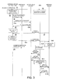
- Fig. 3 is a sequence diagram illustrating an activation method of the transmission device according to the present embodiment.
- step S1 when the power is turned on with the power on operation (step S1), the internal device control section 62 starts operation (step S2), and the CPU 64 starts operation, and starts booting up the OS to be used (sequence S3).
- the internal device control section 62 outputs a connection destination designation command indicating that the connection destination is the internal device control section 62 to the switching device 63 (step S4).
- the switching device 63 establishes connection between the nonvolatile memory 61 and the internal device control section 62.
- internal device control section 62 accesses the nonvolatile memory 61 via the switching device 63 (step S5A), and obtains the setting information about the internal device from the nonvolatile memory 61 (step S5B).
- the internal device control section 62 checks whether there is input and output with the interface 65 (step S6).
- the internal device control section 62 transmits a status information obtaining command to internal device (the exciters 1, 5 and the power amplifier 3) on the basis of the setting information about the internal device.
- the internal device transmits status information to the internal device control section 62, and the internal device control section 62 obtains the status information from the internal device (step S7).
- the internal device control section 62 refers to the obtained status information to determine whether the internal devices are abnormal or not.
- the internal device control section 62 uses an internal device of the backup system instead of the internal device in which the abnormality is detected, or outputs an alarm to warn a user (step S8).
- the internal device control section 62 performs operation start control of the internal device via the interface 65 (step S9A). Therefore, the internal device starts to operate (sequence S9B).
- the CPU 64 completes the booting up of the OS (step S10).
- the internal device control section 62 outputs a connection destination designation command indicating that the connection destination is the CPU 64 to the switching device 63 (step S11).
- the switching device 63 establishes a connection between the nonvolatile memory 61 and the CPU 64 on the basis of the connection destination designation command.
- the CPU 64 accesses the nonvolatile memory 61 via the switching device 63 (step S12A), and obtains the setting information about the internal device from the nonvolatile memory 61 (step S12B).
- the CPU 64 checks whether there is an input and output with the transmission and reception section 66 (step S13).
- the CPU 64 transmits an operation information obtaining command to the exciters 1, 5 and the power amplifier 3 on the basis of the obtained setting information about the internal device via the transmission and reception section 66 (step S14A).
- the CPU 64 obtains the operation information which is output from the exciters 1, 5 and the power amplifier 3 in accordance with the operation information obtaining command (step S14B).
- the CPU 64 refers to the operation information to monitor whether the operation state of the internal device is a steady state or not.
- the transmission device 100 is activated in the steady state.
- the control device 6 includes an internal device control section 62 and a CPU 64.
- the internal device control section 62 performs the operation start control of the internal device, and the CPU 64 starts booting up of the OS in parallel with the operation start control of the internal device with the internal device control section 62.
- the internal device control section 62 is formed with a hardware logic circuit, and therefore, the internal device control section 62 can start the operation of the internal device while the booting up of the OS by the CPU 64.
- the transmission device 100 according to the present embodiment can be activated in a shorter time than a conventional transmission device.
- the CPU 64 After the booting up of the OS is finished, the CPU 64 obtains the operation information from the internal device on the basis of the setting information held in the nonvolatile memory. Therefore, the CPU 64 refers to the obtained operation information to monitor whether the operation state of the internal device is a steady state or not.
- the CPU 64 can control the internal device on the basis of the setting of the internal device which is input by the user.
- the internal device control section 62 obtains the status information which is output from the internal device. Therefore, the internal device control section 62 refers to the obtained status information to determine whether the internal device is abnormal or not. When abnormality is detected in any one of the internal devices, the internal device control section 62 switches the internal device in which the abnormality is detected to the internal device of the backup system, so that the internal device of the backup system can be used, or an alarm can be output to warn the user.
- the internal device control section 62 obtains status information which is output from the internal device when the internal device is operating in the steady state. Therefore, while the internal device is operating in the steady state, the internal device control section 62 refers to the obtained status information to determine whether the internal devices are abnormal or not. When abnormality is detected in any one of the internal devices, the internal device control section 62 can switch the internal device from the main system to the backup system, or output an alarm to warn the user.
- the transmission device receiving the input signals of the two systems has been described, but the embodiment can also be carried out in a transmission device receiving input signals of many systems.
- each of the internal device control section 62 and the CPU 64 may be separately provided with a nonvolatile memory.
- the internal device control section 62 outputs the connection destination designation command to the switching device 63
- the CPU 64 may output a connection destination designation command to the switching device 63.
Landscapes
- Engineering & Computer Science (AREA)
- Software Systems (AREA)
- Theoretical Computer Science (AREA)
- General Engineering & Computer Science (AREA)
- Multimedia (AREA)
- Signal Processing (AREA)
- Computer Security & Cryptography (AREA)
- Physics & Mathematics (AREA)
- General Physics & Mathematics (AREA)
- Transmitters (AREA)
- Stored Programmes (AREA)
Applications Claiming Priority (2)
| Application Number | Priority Date | Filing Date | Title |
|---|---|---|---|
| JP2012204389A JP5450745B1 (ja) | 2012-09-18 | 2012-09-18 | 送信機及び送信機起動方法 |
| PCT/JP2013/004264 WO2014045501A1 (fr) | 2012-09-18 | 2013-07-10 | Émetteur et procédé de démarrage d'émetteur |
Publications (2)
| Publication Number | Publication Date |
|---|---|
| EP2899631A1 true EP2899631A1 (fr) | 2015-07-29 |
| EP2899631A4 EP2899631A4 (fr) | 2016-05-11 |
Family
ID=50340844
Family Applications (1)
| Application Number | Title | Priority Date | Filing Date |
|---|---|---|---|
| EP13839276.6A Withdrawn EP2899631A4 (fr) | 2012-09-18 | 2013-07-10 | Émetteur et procédé de démarrage d'émetteur |
Country Status (5)
| Country | Link |
|---|---|
| US (2) | US20150189340A1 (fr) |
| EP (1) | EP2899631A4 (fr) |
| JP (1) | JP5450745B1 (fr) |
| CN (1) | CN104508631A (fr) |
| WO (1) | WO2014045501A1 (fr) |
Families Citing this family (1)
| Publication number | Priority date | Publication date | Assignee | Title |
|---|---|---|---|---|
| JP2017147503A (ja) * | 2016-02-15 | 2017-08-24 | 株式会社東芝 | 送信システム |
Family Cites Families (11)
| Publication number | Priority date | Publication date | Assignee | Title |
|---|---|---|---|---|
| JP3913892B2 (ja) * | 1998-04-01 | 2007-05-09 | 株式会社東芝 | テレビジョン送信装置の特性補償装置 |
| US6124758A (en) * | 1998-08-19 | 2000-09-26 | Harris Corporation | RF power amplifier control system |
| WO2001042911A2 (fr) * | 1999-12-08 | 2001-06-14 | Insyde Software, Inc. | Systeme et procede de distribution, recherche et affichage d'un contenu avant chargement dans un systeme en exploitation |
| US6721368B1 (en) * | 2000-03-04 | 2004-04-13 | Qualcomm Incorporated | Transmitter architectures for communications systems |
| US8509097B1 (en) * | 2004-08-05 | 2013-08-13 | Cisco Technology, Inc. | Network accessibility to any network attached device during reboot and power loss |
| JP2006262090A (ja) * | 2005-03-17 | 2006-09-28 | Seiko Epson Corp | デジタル放送受信装置 |
| JP4232043B2 (ja) * | 2005-06-08 | 2009-03-04 | ソニー株式会社 | ベース装置、無線通信チャンネル切り替え方法および無線通信チャンネル切り替えプログラム |
| JP5028904B2 (ja) * | 2006-08-10 | 2012-09-19 | ソニー株式会社 | 電子機器、および起動方法 |
| JP2009065367A (ja) * | 2007-09-05 | 2009-03-26 | Toshiba Corp | 放送波送信システム |
| JP2009259076A (ja) | 2008-04-18 | 2009-11-05 | Panasonic Corp | 情報処理装置、情報処理装置の起動方法、撮像システム、rom生成方法、およびrom生成ツール |
| US8798475B2 (en) * | 2011-03-23 | 2014-08-05 | Source Photonics, Inc. | Dynamic memory allocation in an optical transceiver |
-
2012
- 2012-09-18 JP JP2012204389A patent/JP5450745B1/ja active Active
-
2013
- 2013-07-10 CN CN201380039887.9A patent/CN104508631A/zh active Pending
- 2013-07-10 EP EP13839276.6A patent/EP2899631A4/fr not_active Withdrawn
- 2013-07-10 WO PCT/JP2013/004264 patent/WO2014045501A1/fr not_active Ceased
-
2015
- 2015-03-17 US US14/659,687 patent/US20150189340A1/en not_active Abandoned
-
2016
- 2016-10-04 US US15/285,325 patent/US20170090946A1/en not_active Abandoned
Also Published As
| Publication number | Publication date |
|---|---|
| US20150189340A1 (en) | 2015-07-02 |
| CN104508631A (zh) | 2015-04-08 |
| EP2899631A4 (fr) | 2016-05-11 |
| US20170090946A1 (en) | 2017-03-30 |
| JP5450745B1 (ja) | 2014-03-26 |
| JP2014059730A (ja) | 2014-04-03 |
| WO2014045501A1 (fr) | 2014-03-27 |
Similar Documents
| Publication | Publication Date | Title |
|---|---|---|
| JP7147210B2 (ja) | 通信システム、通信装置、制御装置および通信制御方法 | |
| EP4061088B1 (fr) | Procédé de connexion bluetooth, dispositif pouvant être porté par l'utilisateur et support de stockage lisible par ordinateur | |
| KR101668289B1 (ko) | 이동 통신 단말기를 이용한 무선 메쉬 네트워크 기반의 조명 장치 제어 방법 및 이를 실행하기 위한 프로그램을 기록한 컴퓨터로 읽을 수 있는 기록매체 | |
| KR102482670B1 (ko) | 무선 통신 시스템에서 데이터를 송수신하는 전자 장치 및 이를 위한 방법 | |
| CN107528625A (zh) | 用于控制天线的方法和使用天线的电子设备 | |
| US10439865B2 (en) | Wireless relay system, remote unit of wireless relay system, and restoration method of wireless relay system | |
| TWI519082B (zh) | 無線通信裝置及其天線的切換方法 | |
| US20170142517A1 (en) | Method and apparatus for expanded temperature operation of a portable communication device | |
| KR101671063B1 (ko) | 마이크로폰, 마이크로폰 장치 및 마이크로폰에서의 신호들을 처리하기 위한 방법 | |
| EP2899631A1 (fr) | Émetteur et procédé de démarrage d'émetteur | |
| KR102239110B1 (ko) | 통신 서비스 운용 방법 및 전자 장치 | |
| US9524402B2 (en) | Display apparatus and control method thereof | |
| US11496903B2 (en) | Electronic apparatus and controlling method thereof | |
| JP2015092657A5 (fr) | ||
| EP3421896B1 (fr) | Unité intérieure de climatiseur | |
| CN106797228B (zh) | 用于提供通信服务的电子设备和方法 | |
| US9473320B2 (en) | Household appliance and communication control method | |
| JP5411722B2 (ja) | 呼出ランプ制御装置 | |
| US11720318B2 (en) | Audio accessory with high and low impedance paths to a speaker, and a radio for the audio accessory | |
| JP2010258814A (ja) | 通信装置 | |
| WO2015075802A1 (fr) | Système de communication, appareil électroménager, adaptateur de communication, procédé de communication et programme | |
| JP2013258503A (ja) | 受信装置 | |
| WO2019143815A1 (fr) | Re-bander de fréquence doté de caractéristiques d'efficacité de puissance | |
| WO2009090657A3 (fr) | Relais de puissance commandable | |
| JP4670607B2 (ja) | 空気調和機 |
Legal Events
| Date | Code | Title | Description |
|---|---|---|---|
| PUAI | Public reference made under article 153(3) epc to a published international application that has entered the european phase |
Free format text: ORIGINAL CODE: 0009012 |
|
| 17P | Request for examination filed |
Effective date: 20150317 |
|
| AK | Designated contracting states |
Kind code of ref document: A1 Designated state(s): AL AT BE BG CH CY CZ DE DK EE ES FI FR GB GR HR HU IE IS IT LI LT LU LV MC MK MT NL NO PL PT RO RS SE SI SK SM TR |
|
| AX | Request for extension of the european patent |
Extension state: BA ME |
|
| DAX | Request for extension of the european patent (deleted) | ||
| RA4 | Supplementary search report drawn up and despatched (corrected) |
Effective date: 20160412 |
|
| RIC1 | Information provided on ipc code assigned before grant |
Ipc: H04B 1/04 20060101ALI20160406BHEP Ipc: G06F 9/445 20060101AFI20160406BHEP |
|
| STAA | Information on the status of an ep patent application or granted ep patent |
Free format text: STATUS: REQUEST FOR EXAMINATION WAS MADE |
|
| STAA | Information on the status of an ep patent application or granted ep patent |
Free format text: STATUS: THE APPLICATION IS DEEMED TO BE WITHDRAWN |
|
| 18D | Application deemed to be withdrawn |
Effective date: 20161115 |