EP2899637A1 - Dispositif de commande de véhicule électrique - Google Patents
Dispositif de commande de véhicule électrique Download PDFInfo
- Publication number
- EP2899637A1 EP2899637A1 EP13838526.5A EP13838526A EP2899637A1 EP 2899637 A1 EP2899637 A1 EP 2899637A1 EP 13838526 A EP13838526 A EP 13838526A EP 2899637 A1 EP2899637 A1 EP 2899637A1
- Authority
- EP
- European Patent Office
- Prior art keywords
- microcomputer
- power
- reset process
- error
- mode
- Prior art date
- Legal status (The legal status is an assumption and is not a legal conclusion. Google has not performed a legal analysis and makes no representation as to the accuracy of the status listed.)
- Granted
Links
Images


Classifications
-
- B—PERFORMING OPERATIONS; TRANSPORTING
- B60—VEHICLES IN GENERAL
- B60L—PROPULSION OF ELECTRICALLY-PROPELLED VEHICLES; SUPPLYING ELECTRIC POWER FOR AUXILIARY EQUIPMENT OF ELECTRICALLY-PROPELLED VEHICLES; ELECTRODYNAMIC BRAKE SYSTEMS FOR VEHICLES IN GENERAL; MAGNETIC SUSPENSION OR LEVITATION FOR VEHICLES; MONITORING OPERATING VARIABLES OF ELECTRICALLY-PROPELLED VEHICLES; ELECTRIC SAFETY DEVICES FOR ELECTRICALLY-PROPELLED VEHICLES
- B60L3/00—Electric devices on electrically-propelled vehicles for safety purposes; Monitoring operating variables, e.g. speed, deceleration or energy consumption
- B60L3/04—Cutting off the power supply under fault conditions
-
- B—PERFORMING OPERATIONS; TRANSPORTING
- B60—VEHICLES IN GENERAL
- B60L—PROPULSION OF ELECTRICALLY-PROPELLED VEHICLES; SUPPLYING ELECTRIC POWER FOR AUXILIARY EQUIPMENT OF ELECTRICALLY-PROPELLED VEHICLES; ELECTRODYNAMIC BRAKE SYSTEMS FOR VEHICLES IN GENERAL; MAGNETIC SUSPENSION OR LEVITATION FOR VEHICLES; MONITORING OPERATING VARIABLES OF ELECTRICALLY-PROPELLED VEHICLES; ELECTRIC SAFETY DEVICES FOR ELECTRICALLY-PROPELLED VEHICLES
- B60L15/00—Methods, circuits, or devices for controlling the traction-motor speed of electrically-propelled vehicles
- B60L15/20—Methods, circuits, or devices for controlling the traction-motor speed of electrically-propelled vehicles for control of the vehicle or its driving motor to achieve a desired performance, e.g. speed, torque, programmed variation of speed
-
- B—PERFORMING OPERATIONS; TRANSPORTING
- B60—VEHICLES IN GENERAL
- B60L—PROPULSION OF ELECTRICALLY-PROPELLED VEHICLES; SUPPLYING ELECTRIC POWER FOR AUXILIARY EQUIPMENT OF ELECTRICALLY-PROPELLED VEHICLES; ELECTRODYNAMIC BRAKE SYSTEMS FOR VEHICLES IN GENERAL; MAGNETIC SUSPENSION OR LEVITATION FOR VEHICLES; MONITORING OPERATING VARIABLES OF ELECTRICALLY-PROPELLED VEHICLES; ELECTRIC SAFETY DEVICES FOR ELECTRICALLY-PROPELLED VEHICLES
- B60L3/00—Electric devices on electrically-propelled vehicles for safety purposes; Monitoring operating variables, e.g. speed, deceleration or energy consumption
- B60L3/0023—Detecting, eliminating, remedying or compensating for drive train abnormalities, e.g. failures within the drive train
- B60L3/0084—Detecting, eliminating, remedying or compensating for drive train abnormalities, e.g. failures within the drive train relating to control modules
-
- B—PERFORMING OPERATIONS; TRANSPORTING
- B60—VEHICLES IN GENERAL
- B60L—PROPULSION OF ELECTRICALLY-PROPELLED VEHICLES; SUPPLYING ELECTRIC POWER FOR AUXILIARY EQUIPMENT OF ELECTRICALLY-PROPELLED VEHICLES; ELECTRODYNAMIC BRAKE SYSTEMS FOR VEHICLES IN GENERAL; MAGNETIC SUSPENSION OR LEVITATION FOR VEHICLES; MONITORING OPERATING VARIABLES OF ELECTRICALLY-PROPELLED VEHICLES; ELECTRIC SAFETY DEVICES FOR ELECTRICALLY-PROPELLED VEHICLES
- B60L50/00—Electric propulsion with power supplied within the vehicle
- B60L50/50—Electric propulsion with power supplied within the vehicle using propulsion power supplied by batteries or fuel cells
- B60L50/51—Electric propulsion with power supplied within the vehicle using propulsion power supplied by batteries or fuel cells characterised by AC-motors
-
- B—PERFORMING OPERATIONS; TRANSPORTING
- B60—VEHICLES IN GENERAL
- B60L—PROPULSION OF ELECTRICALLY-PROPELLED VEHICLES; SUPPLYING ELECTRIC POWER FOR AUXILIARY EQUIPMENT OF ELECTRICALLY-PROPELLED VEHICLES; ELECTRODYNAMIC BRAKE SYSTEMS FOR VEHICLES IN GENERAL; MAGNETIC SUSPENSION OR LEVITATION FOR VEHICLES; MONITORING OPERATING VARIABLES OF ELECTRICALLY-PROPELLED VEHICLES; ELECTRIC SAFETY DEVICES FOR ELECTRICALLY-PROPELLED VEHICLES
- B60L50/00—Electric propulsion with power supplied within the vehicle
- B60L50/50—Electric propulsion with power supplied within the vehicle using propulsion power supplied by batteries or fuel cells
- B60L50/60—Electric propulsion with power supplied within the vehicle using propulsion power supplied by batteries or fuel cells using power supplied by batteries
- B60L50/61—Electric propulsion with power supplied within the vehicle using propulsion power supplied by batteries or fuel cells using power supplied by batteries by batteries charged by engine-driven generators, e.g. series hybrid electric vehicles
-
- B—PERFORMING OPERATIONS; TRANSPORTING
- B60—VEHICLES IN GENERAL
- B60L—PROPULSION OF ELECTRICALLY-PROPELLED VEHICLES; SUPPLYING ELECTRIC POWER FOR AUXILIARY EQUIPMENT OF ELECTRICALLY-PROPELLED VEHICLES; ELECTRODYNAMIC BRAKE SYSTEMS FOR VEHICLES IN GENERAL; MAGNETIC SUSPENSION OR LEVITATION FOR VEHICLES; MONITORING OPERATING VARIABLES OF ELECTRICALLY-PROPELLED VEHICLES; ELECTRIC SAFETY DEVICES FOR ELECTRICALLY-PROPELLED VEHICLES
- B60L58/00—Methods or circuit arrangements for monitoring or controlling batteries or fuel cells, specially adapted for electric vehicles
- B60L58/10—Methods or circuit arrangements for monitoring or controlling batteries or fuel cells, specially adapted for electric vehicles for monitoring or controlling batteries
- B60L58/18—Methods or circuit arrangements for monitoring or controlling batteries or fuel cells, specially adapted for electric vehicles for monitoring or controlling batteries of two or more battery modules
- B60L58/20—Methods or circuit arrangements for monitoring or controlling batteries or fuel cells, specially adapted for electric vehicles for monitoring or controlling batteries of two or more battery modules having different nominal voltages
-
- B—PERFORMING OPERATIONS; TRANSPORTING
- B60—VEHICLES IN GENERAL
- B60L—PROPULSION OF ELECTRICALLY-PROPELLED VEHICLES; SUPPLYING ELECTRIC POWER FOR AUXILIARY EQUIPMENT OF ELECTRICALLY-PROPELLED VEHICLES; ELECTRODYNAMIC BRAKE SYSTEMS FOR VEHICLES IN GENERAL; MAGNETIC SUSPENSION OR LEVITATION FOR VEHICLES; MONITORING OPERATING VARIABLES OF ELECTRICALLY-PROPELLED VEHICLES; ELECTRIC SAFETY DEVICES FOR ELECTRICALLY-PROPELLED VEHICLES
- B60L58/00—Methods or circuit arrangements for monitoring or controlling batteries or fuel cells, specially adapted for electric vehicles
- B60L58/10—Methods or circuit arrangements for monitoring or controlling batteries or fuel cells, specially adapted for electric vehicles for monitoring or controlling batteries
- B60L58/18—Methods or circuit arrangements for monitoring or controlling batteries or fuel cells, specially adapted for electric vehicles for monitoring or controlling batteries of two or more battery modules
- B60L58/21—Methods or circuit arrangements for monitoring or controlling batteries or fuel cells, specially adapted for electric vehicles for monitoring or controlling batteries of two or more battery modules having the same nominal voltage
-
- G—PHYSICS
- G06—COMPUTING OR CALCULATING; COUNTING
- G06F—ELECTRIC DIGITAL DATA PROCESSING
- G06F1/00—Details not covered by groups G06F3/00 - G06F13/00 and G06F21/00
- G06F1/24—Resetting means
-
- G—PHYSICS
- G06—COMPUTING OR CALCULATING; COUNTING
- G06F—ELECTRIC DIGITAL DATA PROCESSING
- G06F11/00—Error detection; Error correction; Monitoring
-
- G—PHYSICS
- G06—COMPUTING OR CALCULATING; COUNTING
- G06F—ELECTRIC DIGITAL DATA PROCESSING
- G06F11/00—Error detection; Error correction; Monitoring
- G06F11/07—Responding to the occurrence of a fault, e.g. fault tolerance
- G06F11/0703—Error or fault processing not based on redundancy, i.e. by taking additional measures to deal with the error or fault not making use of redundancy in operation, in hardware, or in data representation
- G06F11/0706—Error or fault processing not based on redundancy, i.e. by taking additional measures to deal with the error or fault not making use of redundancy in operation, in hardware, or in data representation the processing taking place on a specific hardware platform or in a specific software environment
- G06F11/0736—Error or fault processing not based on redundancy, i.e. by taking additional measures to deal with the error or fault not making use of redundancy in operation, in hardware, or in data representation the processing taking place on a specific hardware platform or in a specific software environment in functional embedded systems, i.e. in a data processing system designed as a combination of hardware and software dedicated to performing a certain function
- G06F11/0739—Error or fault processing not based on redundancy, i.e. by taking additional measures to deal with the error or fault not making use of redundancy in operation, in hardware, or in data representation the processing taking place on a specific hardware platform or in a specific software environment in functional embedded systems, i.e. in a data processing system designed as a combination of hardware and software dedicated to performing a certain function in a data processing system embedded in automotive or aircraft systems
-
- G—PHYSICS
- G06—COMPUTING OR CALCULATING; COUNTING
- G06F—ELECTRIC DIGITAL DATA PROCESSING
- G06F11/00—Error detection; Error correction; Monitoring
- G06F11/07—Responding to the occurrence of a fault, e.g. fault tolerance
- G06F11/0703—Error or fault processing not based on redundancy, i.e. by taking additional measures to deal with the error or fault not making use of redundancy in operation, in hardware, or in data representation
- G06F11/0793—Remedial or corrective actions
-
- G—PHYSICS
- G06—COMPUTING OR CALCULATING; COUNTING
- G06F—ELECTRIC DIGITAL DATA PROCESSING
- G06F11/00—Error detection; Error correction; Monitoring
- G06F11/30—Monitoring
-
- B—PERFORMING OPERATIONS; TRANSPORTING
- B60—VEHICLES IN GENERAL
- B60L—PROPULSION OF ELECTRICALLY-PROPELLED VEHICLES; SUPPLYING ELECTRIC POWER FOR AUXILIARY EQUIPMENT OF ELECTRICALLY-PROPELLED VEHICLES; ELECTRODYNAMIC BRAKE SYSTEMS FOR VEHICLES IN GENERAL; MAGNETIC SUSPENSION OR LEVITATION FOR VEHICLES; MONITORING OPERATING VARIABLES OF ELECTRICALLY-PROPELLED VEHICLES; ELECTRIC SAFETY DEVICES FOR ELECTRICALLY-PROPELLED VEHICLES
- B60L2210/00—Converter types
- B60L2210/10—DC to DC converters
-
- B—PERFORMING OPERATIONS; TRANSPORTING
- B60—VEHICLES IN GENERAL
- B60L—PROPULSION OF ELECTRICALLY-PROPELLED VEHICLES; SUPPLYING ELECTRIC POWER FOR AUXILIARY EQUIPMENT OF ELECTRICALLY-PROPELLED VEHICLES; ELECTRODYNAMIC BRAKE SYSTEMS FOR VEHICLES IN GENERAL; MAGNETIC SUSPENSION OR LEVITATION FOR VEHICLES; MONITORING OPERATING VARIABLES OF ELECTRICALLY-PROPELLED VEHICLES; ELECTRIC SAFETY DEVICES FOR ELECTRICALLY-PROPELLED VEHICLES
- B60L2220/00—Electrical machine types; Structures or applications thereof
- B60L2220/10—Electrical machine types
- B60L2220/14—Synchronous machines
-
- B—PERFORMING OPERATIONS; TRANSPORTING
- B60—VEHICLES IN GENERAL
- B60L—PROPULSION OF ELECTRICALLY-PROPELLED VEHICLES; SUPPLYING ELECTRIC POWER FOR AUXILIARY EQUIPMENT OF ELECTRICALLY-PROPELLED VEHICLES; ELECTRODYNAMIC BRAKE SYSTEMS FOR VEHICLES IN GENERAL; MAGNETIC SUSPENSION OR LEVITATION FOR VEHICLES; MONITORING OPERATING VARIABLES OF ELECTRICALLY-PROPELLED VEHICLES; ELECTRIC SAFETY DEVICES FOR ELECTRICALLY-PROPELLED VEHICLES
- B60L2240/00—Control parameters of input or output; Target parameters
- B60L2240/40—Drive Train control parameters
- B60L2240/42—Drive Train control parameters related to electric machines
- B60L2240/423—Torque
-
- B—PERFORMING OPERATIONS; TRANSPORTING
- B60—VEHICLES IN GENERAL
- B60L—PROPULSION OF ELECTRICALLY-PROPELLED VEHICLES; SUPPLYING ELECTRIC POWER FOR AUXILIARY EQUIPMENT OF ELECTRICALLY-PROPELLED VEHICLES; ELECTRODYNAMIC BRAKE SYSTEMS FOR VEHICLES IN GENERAL; MAGNETIC SUSPENSION OR LEVITATION FOR VEHICLES; MONITORING OPERATING VARIABLES OF ELECTRICALLY-PROPELLED VEHICLES; ELECTRIC SAFETY DEVICES FOR ELECTRICALLY-PROPELLED VEHICLES
- B60L2240/00—Control parameters of input or output; Target parameters
- B60L2240/40—Drive Train control parameters
- B60L2240/42—Drive Train control parameters related to electric machines
- B60L2240/429—Current
-
- G—PHYSICS
- G06—COMPUTING OR CALCULATING; COUNTING
- G06F—ELECTRIC DIGITAL DATA PROCESSING
- G06F11/00—Error detection; Error correction; Monitoring
- G06F11/07—Responding to the occurrence of a fault, e.g. fault tolerance
- G06F11/0796—Safety measures, i.e. ensuring safe condition in the event of error, e.g. for controlling element
-
- Y—GENERAL TAGGING OF NEW TECHNOLOGICAL DEVELOPMENTS; GENERAL TAGGING OF CROSS-SECTIONAL TECHNOLOGIES SPANNING OVER SEVERAL SECTIONS OF THE IPC; TECHNICAL SUBJECTS COVERED BY FORMER USPC CROSS-REFERENCE ART COLLECTIONS [XRACs] AND DIGESTS
- Y02—TECHNOLOGIES OR APPLICATIONS FOR MITIGATION OR ADAPTATION AGAINST CLIMATE CHANGE
- Y02T—CLIMATE CHANGE MITIGATION TECHNOLOGIES RELATED TO TRANSPORTATION
- Y02T10/00—Road transport of goods or passengers
- Y02T10/60—Other road transportation technologies with climate change mitigation effect
- Y02T10/62—Hybrid vehicles
-
- Y—GENERAL TAGGING OF NEW TECHNOLOGICAL DEVELOPMENTS; GENERAL TAGGING OF CROSS-SECTIONAL TECHNOLOGIES SPANNING OVER SEVERAL SECTIONS OF THE IPC; TECHNICAL SUBJECTS COVERED BY FORMER USPC CROSS-REFERENCE ART COLLECTIONS [XRACs] AND DIGESTS
- Y02—TECHNOLOGIES OR APPLICATIONS FOR MITIGATION OR ADAPTATION AGAINST CLIMATE CHANGE
- Y02T—CLIMATE CHANGE MITIGATION TECHNOLOGIES RELATED TO TRANSPORTATION
- Y02T10/00—Road transport of goods or passengers
- Y02T10/60—Other road transportation technologies with climate change mitigation effect
- Y02T10/64—Electric machine technologies in electromobility
-
- Y—GENERAL TAGGING OF NEW TECHNOLOGICAL DEVELOPMENTS; GENERAL TAGGING OF CROSS-SECTIONAL TECHNOLOGIES SPANNING OVER SEVERAL SECTIONS OF THE IPC; TECHNICAL SUBJECTS COVERED BY FORMER USPC CROSS-REFERENCE ART COLLECTIONS [XRACs] AND DIGESTS
- Y02—TECHNOLOGIES OR APPLICATIONS FOR MITIGATION OR ADAPTATION AGAINST CLIMATE CHANGE
- Y02T—CLIMATE CHANGE MITIGATION TECHNOLOGIES RELATED TO TRANSPORTATION
- Y02T10/00—Road transport of goods or passengers
- Y02T10/60—Other road transportation technologies with climate change mitigation effect
- Y02T10/70—Energy storage systems for electromobility, e.g. batteries
-
- Y—GENERAL TAGGING OF NEW TECHNOLOGICAL DEVELOPMENTS; GENERAL TAGGING OF CROSS-SECTIONAL TECHNOLOGIES SPANNING OVER SEVERAL SECTIONS OF THE IPC; TECHNICAL SUBJECTS COVERED BY FORMER USPC CROSS-REFERENCE ART COLLECTIONS [XRACs] AND DIGESTS
- Y02—TECHNOLOGIES OR APPLICATIONS FOR MITIGATION OR ADAPTATION AGAINST CLIMATE CHANGE
- Y02T—CLIMATE CHANGE MITIGATION TECHNOLOGIES RELATED TO TRANSPORTATION
- Y02T10/00—Road transport of goods or passengers
- Y02T10/60—Other road transportation technologies with climate change mitigation effect
- Y02T10/7072—Electromobility specific charging systems or methods for batteries, ultracapacitors, supercapacitors or double-layer capacitors
-
- Y—GENERAL TAGGING OF NEW TECHNOLOGICAL DEVELOPMENTS; GENERAL TAGGING OF CROSS-SECTIONAL TECHNOLOGIES SPANNING OVER SEVERAL SECTIONS OF THE IPC; TECHNICAL SUBJECTS COVERED BY FORMER USPC CROSS-REFERENCE ART COLLECTIONS [XRACs] AND DIGESTS
- Y02—TECHNOLOGIES OR APPLICATIONS FOR MITIGATION OR ADAPTATION AGAINST CLIMATE CHANGE
- Y02T—CLIMATE CHANGE MITIGATION TECHNOLOGIES RELATED TO TRANSPORTATION
- Y02T10/00—Road transport of goods or passengers
- Y02T10/60—Other road transportation technologies with climate change mitigation effect
- Y02T10/72—Electric energy management in electromobility
Definitions
- the present invention relates to an electric vehicle control device that is provided with two mutually monitoring microcomputers and performs a reset process (initialization process) when an error in microcomputer operation is identified.
- Patent Document 1 Laid-open Japanese Patent Application Publication No. H10-177504
- a power relay of the onboard power system is forcibly turned off as a fail-safe function regardless of whether power is flowing through the onboard power system due to battery charging or discharging.
- the present invention was conceived in view of the problem described above, it being an object thereof to provide an electric vehicle control device that prevents fusion in a power relay when a reset is performed as the result of a microcomputer operation error not caused by a microcomputer error being identified.
- an electric vehicle control device is assumed to be provided with a first microcomputer and a second microcomputer that share a power source, possess separate control functions, and allow for independent rewriting of their respective control programs, and reset process means for monitoring mutual microcomputer operation of the first microcomputer and the second microcomputer and performing a reset process that turns off a power relay belonging to an onboard power system when a microcomputer operation error is identified.
- the reset process means comprises a power shut-off reset process unit for performing a reset process that shuts off the flow of power through the onboard power system and turns off the power relay in this powered-off state when resetting due to a microcomputer operation error not caused by a microcomputer error being identified.
- the power shut-off reset process unit When resetting due to a microcomputer operation error not caused by a microcomputer error being identified, the power shut-off reset process unit thus performs a reset process in which the flow of power through the onboard power system is shut off, and the power relay is turned off in this powered-off state.
- Turning off the power relay in a powered-off state thus eliminates sparking at switch contacts, keeping a switch of the power relay from fusing in an on state.
- FIG. 1 is an overall system diagram showing an electric car control device according to a first embodiment. The following is a description of the overall system configuration based on FIG. 1 .
- An electric car (EV) to which the control device of the first embodiment is applied is provided with an electronic control unit 1 (ECU), a fail-safe relay 2, a battery pack 3, a DC/DC junction box 4, a drive motor inverter 5, a drive motor 6, a gear reducer 7, and a 12 V battery 8, as shown in FIG. 1 .
- ECU electronice control unit 1
- fail-safe relay 2 a fail-safe relay 2
- battery pack 3 a DC/DC junction box 4
- a drive motor inverter 5 a drive motor 6, a gear reducer 7, and a 12 V battery 8
- a 12 V battery 8 12 V battery 8
- the electronic control unit 1 is disposed, for example, in the interior of an instrument panel, and comprises a first microcomputer 11, a second microcomputer 12, a power source IC circuit 13, and a fail-safe circuit 14.
- the first microcomputer 11 and the second microcomputer 12 share the 12 V battery 8 and the power source IC circuit 13 (power source), have separate control functions, and allow for independent rewriting of their respective control programs.
- the first microcomputer 11 comprises a program storage region 11a, a microcomputer function 2 monitoring unit 11b, and an inter-CPU communication diagnostic unit 11c.
- the second microcomputer 12 comprises a program storage region 12a, a microcomputer function 1 monitoring unit 12b, and an inter-CPU communication diagnostic unit 12c.
- the microcomputer function 2 monitoring unit 11b and the microcomputer function 1 monitoring unit 12b mutually monitor microcomputer operation, and, when a microcomputer operation error is identified, perform a reset process that turns off power relays 31, 32 belonging to the onboard power system (reset process means).
- the first microcomputer 11 can be, for example, a VCM main microcomputer into which signals from various sensors and controllers are input via a CAN communications line and which assesses vehicle state on the basis of the inputted signals and comprehensively performs various control processes of the EV system.
- the second microcomputer 12 can be, for example, a VCM sub + PBW microcomputer featuring a VCM sub-microcomputer, having the same functions as the VCM main microcomputer, to which a PBW microcomputer has been added.
- This PBW microcomputer is a controller for outputting drive commands to a parking actuator 71 that controls the locking and unlocking of a parking mechanism within the gear reducer 7 on the basis of signals from a P-range switch not shown in the drawings.
- VCM is an abbreviation for "vehicle control module”
- PBW is an abbreviation for "park by wire”.
- the fail-safe circuit 14 is constituted by an OR circuit that outputs an OFF command to the fail-safe relay 2 when a fail-safe relay cut signal is inputted from at least one of the first microcomputer 11 or the second microcomputer 12.
- the first microcomputer 11 and the second microcomputer 12 are connected by a serial communication line 15, a WDT signal line 16 for outputting a WDT signal from the second microcomputer 12 to the first microcomputer 11, and an RST signal line 17 for outputting an RST signal from the first microcomputer 11 to the second microcomputer 12.
- the first microcomputer 11 and the power source IC circuit 13 are connected by a WDT signal line 18 for outputting a WDT signal from the first microcomputer 11 to the power source IC circuit 13.
- the first microcomputer 11, the second microcomputer 12, and the power source IC circuit 13 are connected by an RST signal line 19 for outputting an RST signal from the power source IC circuit 13 to the first microcomputer 11 and the second microcomputer 12.
- the first microcomputer 11 and the fail-safe circuit 14 are connected by a first fail-safe relay cut signal line 20, and the second microcomputer 12 and the fail-safe circuit 14 are connected by a second fail-safe relay cut signal line 21.
- the WDT signal is a watchdog timer signal the level of which is inverted at predetermined time intervals in order to monitor errors in microcomputer operation.
- the RST signal is a reset signal for requesting a reset process.
- the battery pack 3 is disposed, for example, at an under-floor position in the center of the wheelbase, and comprises a module stack 30, the first power relay 31, and the second power relay 32.
- the module stack 30 is constituted by a stack of multiple modules, each constituted by a bundle of multiple laminated cells, and has a rated voltage output of DC 360 V if, for example, a 48-module lithium ion cell.
- the first power relay 21 and the second power relay 22 are built into the battery pack 3, and connect and disconnect the positive and negative sides of the module stack 30 and the DC/DC junction box 4.
- the onboard power system is constituted by the battery pack 3, the DC/DC junction box 4, the drive motor inverter 5, and the drive motor 6.
- the DC/DC junction box 4 has a built-in DC/DC converter for distributing high-voltage power from the battery pack 3, supplying electrical power to the 12 V power system, and charging the 12 V battery 8.
- the DC/DC junction box 4 also comprises an ordinary charging relay and a rapid charging relay, and can switch between charging circuits according to charging mode.
- the drive motor inverter 5 converts DC electrical power from the DC/DC junction box 4 to AC electrical power on the basis of a drive torque signal sent from the VCM via the CAN communications line, and supplies AC electrical power to the drive motor 6 in the form of three-phase alternating current.
- the drive motor inverter 5 comprises a motor controller, a driver, a smoothing capacitor, a current sensor, and a power module.
- the drive motor 6 is disposed in a motor chamber as a travel drive source, and is constituted by a permanent magnet synchronous motor. When a positive torque command is issued, the drive motor 6 engages in driving operation for generating drive torque using electrical power discharged from the battery pack 3 (motoring). Conversely, when a negative torque command is issued, the drive motor 6 engages in power generation operation for converting rotational energy from the left and right drive wheels to electrical energy, and uses the generating electrical power to charge the battery pack 3 (regenerating).
- the gear reducer 7 comprises a parking mechanism provided with the parking actuator 71, an input side of the gear reducer being linked to the drive motor 6, and a differential gear unit on an output side of the gear reducer being linked to left and right drive wheels.
- the 12 V battery 8 is a power source for the electronic control unit 1, and is also a power source for various other onboard electronic equipment, such as a relay actuation power source for the first power relay 21 and the second power relay 22.
- the 12 V battery 8 monitors 12 V battery voltage, and is controlled so as to automatically charge using electrical power from the battery pack 3 when the 12 V battery voltage falls.
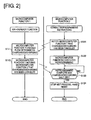
- FIG. 2 shows the flow of a power shut-off reset process executed by the first microcomputer and the second microcomputer when the control program of the second microcomputer is rewritten
- FIG. 3 shows scenarios of mode transitions between a normal mode, in which the power shut-off reset process is performed, and a wake-up mode.
- the detailed configuration of the power shut-off reset process will now be described with reference to FIGS. 1-3 .
- the basic function of the microcomputer function 2 monitoring unit 11b and the microcomputer function 1 monitoring unit 12b is to mutually monitor microcomputer operation, and, when a microcomputer operation error is identified, perform a reset process that turns off power relays 31, 32 belonging to the onboard power system (reset process means).
- reset process means a reset process that shuts off the flow of power through the onboard power system and turns off the power relays 31, 32 in this powered-off state is performed when resetting due to a microcomputer operation error not caused by a microcomputer error being identified (power shut-off reset process).
- the microcomputer function 1 In the microcomputer function 2 process performed by the second microcomputer 12, when reprogramming instructions are issued, the microcomputer function 1 is first notified via communication of a command to cancel charging and discharging in step S121 before reprogramming is begun. After notification of the charging/discharging cancellation command has been issued, the microcomputer function 2 begins reprogramming in step S122. Then, in step S 123, it is assessed whether reprogramming complete conditions and charging/discharging shut-off complete conditions have been met. The assessment regarding reprogramming complete conditions is made by the microcomputer function 2, and the assessment regarding charging/discharging shut-off complete conditions is made on the basis on notification information received via communication from the microcomputer function 1.
- the 12 V battery 8 shown in FIG. 1 monitors 12 V battery voltage, thereby inputting 12 V battery voltage monitoring data via the CAN communications line, and identifies a low-voltage scenario if the power source voltage of the first microcomputer 11 and the second microcomputer 12 is lower than a voltage threshold value capable of ensuring normal operation.
- a process of first shutting off the flow of power through the power system is added, and a reset process of shutting off the flow of power through the onboard power system via charging and discharging and turning the power relays 31, 32 off in this powered-off state is performed.
- An onboard electronic control system possesses a normal mode in which an onboard power source switch (ignition switch) is on, and a wake-up mode in which the onboard power source switch is off but the necessary operation of an onboard controller is ensured.
- IGN mode normal mode
- WakeUp mode wake-up mode
- IGN-OFF & ReadyToSleep is received in IGN mode, as well as GoToSleep from a master
- the mode shifts to off mode.
- off mode when IGN-OFF & WakeUp-ON is received, the mode shifts to WakeUp mode.
- the WDT signal outputted from the first microcomputer 11 to the power source IC circuit 13 via the WDT signal line 18 is stopped.
- a microcomputer operation error is identified through this stoppage of the WDT signal, and an RST signal is simultaneously outputted from the power source IC circuit 13 to the first microcomputer 11 and the second microcomputer 12 via the RST signal line 19.
- the first microcomputer 11 Upon receiving the RST signal, the first microcomputer 11 outputs a first fail-safe relay cut signal to the fail-safe circuit 14 via the first fail-safe relay cut signal line 20.
- the second microcomputer 12 upon receiving the RST signal, outputs a second fail-safe relay cut signal to the fail-safe circuit 14 via the second fail-safe relay cut signal line 21.
- the fail-safe relay 2 cuts off the relay actuation power source of the power relays 31, 32 belonging to the onboard power system, turning the power relays 31, 32 off.
- a microcomputer operation error is identified by monitoring the WDT signal, at which point the power relays 31, 32 are immediately turned off, manifesting the fail-safe function for the reset process.
- the microcomputer function 1 is first notified via communication of a command to cancel charging and discharging in step S121 before reprogramming is begun. After notification of the charging/discharging cancellation command has been issued, reprogramming of the microcomputer function 2 is begun in the subsequent step S122.
- step S123 reset process permission conditions are assessed, and if it is confirmed that reprogramming complete conditions and charging/discharging shut-off complete conditions have been met, the process continues to step S124, WDT processing is stopped, and a hard reset process (i.e., a process of turning the power relays 31, 32 off) is forcibly performed.
- a hard reset process i.e., a process of turning the power relays 31, 32 off
- the microcomputer function 2 When reprogramming instructions are issued with consult reprogramming instructions as a trigger, the microcomputer function 2 first notifies the microcomputer function 1 via communication that power is to be shut off, and the reprogramming of the microcomputer function 2 is begun. The two operations of reprogramming the microcomputer function 2 and shutting off the power by the microcomputer function 1 are performed simultaneously. Then, once it has been confirmed via communication from the microcomputer function 1 that the power has been shut off and reprogramming of the second microcomputer 12 is complete, a microcomputer function 2 reset process is executed.
- the timing at which the reset process for turning off the power relays 31, 32 is begun would be delayed by the same length of time that was waited for the power to be completely shut off.
- 12 V battery voltage monitoring data is inputted from the automatic charging control system of the 12 V battery 8 via the CAN communications line, and a low-voltage scenario is identified if the power source voltage of the first microcomputer 11 and the second microcomputer 12 is lower than a voltage threshold value capable of ensuring normal operation.
- a process of first shutting off the flow of power through the power system is added, and a reset process of shutting off the flow of power through the onboard power system via charging and discharging and turning the power relays 31, 32 off in this powered-off state is performed.
- a process of first shutting off the flow of power through the power system when entering off mode is added, and a reset process of shutting off the flow of power through the onboard power system via charging and discharging and turning off the power relays 31, 32 in this powered-off state is performed.
- An electric vehicle (electric car) control device characterized in being provided with:
- the power shut-off reset process unit treats a reset performed due to the identification of a microcomputer operation error not caused by a microcomputer error as a reprogramming scenario in which a control program of either the first microcomputer 11 or the second microcomputer 12 is rewritten ( FIG. 2 ).
- the power shut-off reset process unit begins reprogramming when instructions to first shut off the flow of power through the onboard power system are issued via communication from the microcomputer for which the control program is being rewritten to the other microcomputer, and, after it has been confirmed via communication from the other microcomputer to the first microcomputer that the flow of power has been shut off, and it has been confirmed that reprogramming is complete, a reset process for turning off the power relays 31, 32 is performed ( FIG. 4 ).
- fusion in the power relays 31, 32 can be reliably prevented when resetting in a reprogramming scenario, allowing the timing at which the reset process for turning off the power relays 31, 32 is begun to be advanced.
Landscapes
- Engineering & Computer Science (AREA)
- Theoretical Computer Science (AREA)
- Transportation (AREA)
- Mechanical Engineering (AREA)
- Power Engineering (AREA)
- Sustainable Energy (AREA)
- Life Sciences & Earth Sciences (AREA)
- Sustainable Development (AREA)
- Physics & Mathematics (AREA)
- General Engineering & Computer Science (AREA)
- General Physics & Mathematics (AREA)
- Quality & Reliability (AREA)
- Electric Propulsion And Braking For Vehicles (AREA)
- Charge And Discharge Circuits For Batteries Or The Like (AREA)
- Debugging And Monitoring (AREA)
Applications Claiming Priority (2)
| Application Number | Priority Date | Filing Date | Title |
|---|---|---|---|
| JP2012209821 | 2012-09-24 | ||
| PCT/JP2013/072215 WO2014045785A1 (fr) | 2012-09-24 | 2013-08-20 | Dispositif de commande de véhicule électrique |
Publications (3)
| Publication Number | Publication Date |
|---|---|
| EP2899637A1 true EP2899637A1 (fr) | 2015-07-29 |
| EP2899637A4 EP2899637A4 (fr) | 2015-12-16 |
| EP2899637B1 EP2899637B1 (fr) | 2017-04-26 |
Family
ID=50341109
Family Applications (1)
| Application Number | Title | Priority Date | Filing Date |
|---|---|---|---|
| EP13838526.5A Active EP2899637B1 (fr) | 2012-09-24 | 2013-08-20 | Dispositif de commande de véhicule électrique |
Country Status (6)
| Country | Link |
|---|---|
| US (1) | US9216651B2 (fr) |
| EP (1) | EP2899637B1 (fr) |
| JP (1) | JP5817935B2 (fr) |
| KR (2) | KR20160035092A (fr) |
| CN (1) | CN104641354B (fr) |
| WO (1) | WO2014045785A1 (fr) |
Families Citing this family (18)
| Publication number | Priority date | Publication date | Assignee | Title |
|---|---|---|---|---|
| JP2017033236A (ja) * | 2015-07-31 | 2017-02-09 | 日立オートモティブシステムズ株式会社 | 車両制御装置 |
| JP6742192B2 (ja) * | 2016-08-09 | 2020-08-19 | 日立オートモティブシステムズ株式会社 | 電子制御装置 |
| CN106627154A (zh) * | 2016-10-21 | 2017-05-10 | 深圳市沃特玛电池有限公司 | 电动汽车及其主机 |
| JP6753388B2 (ja) * | 2017-11-13 | 2020-09-09 | 株式会社デンソー | 自動運転制御装置、車両の自動運転制御方法 |
| CN107856538A (zh) * | 2017-11-14 | 2018-03-30 | 华晨汽车集团控股有限公司 | 一种电动汽车电驱动系统工作模式切换控制方法 |
| DE102017220481A1 (de) * | 2017-11-16 | 2019-05-16 | Robert Bosch Gmbh | Vorrichtung zum Steuern von Funktionen für ein Fahrzeug, Fahrzeugsystem für ein Fahrzeug und Verfahren zum Rücksetzen elektrischer Schaltungen einer Vorrichtung zum Steuern von Funktionen für ein Fahrzeug |
| DE112019000335B4 (de) * | 2018-02-15 | 2025-10-02 | Hitachi Astemo, Ltd. | Batteriemanagementeinheit |
| DE102018104914A1 (de) * | 2018-03-05 | 2019-09-05 | Dr. Ing. H.C. F. Porsche Aktiengesellschaft | Integrierte Power Box |
| CN110262297B (zh) | 2018-09-21 | 2020-10-02 | 宁德时代新能源科技股份有限公司 | 继电器控制装置及供电系统 |
| JP7243459B2 (ja) * | 2019-05-31 | 2023-03-22 | 株式会社デンソー | 車両用装置 |
| CN110828916A (zh) * | 2019-11-01 | 2020-02-21 | 天津市捷威动力工业有限公司 | 一种电池系统高压继电器控制装置及控制方法 |
| KR102269546B1 (ko) * | 2020-02-26 | 2021-06-28 | 슈어소프트테크주식회사 | 결함 주입 장치 |
| JP2021158727A (ja) * | 2020-03-25 | 2021-10-07 | 河村電器産業株式会社 | Bms監視システム |
| FR3109256A1 (fr) * | 2020-04-08 | 2021-10-15 | Psa Automobiles Sa | Procédé, dispositif et système de détermination d’un état de fonctionnement d’un calculateur de véhicule |
| JP7490768B2 (ja) * | 2020-05-28 | 2024-05-27 | 日産自動車株式会社 | 電源システム及び電源システムの制御方法 |
| FR3115373B1 (fr) * | 2020-10-20 | 2023-06-02 | Psa Automobiles Sa | Gestion de la supervision d’un composant électronique d’un véhicule terrestre à moteur |
| CN116802085A (zh) * | 2021-01-29 | 2023-09-22 | 日立安斯泰莫株式会社 | 车载设备的电子控制装置 |
| JP7816220B2 (ja) * | 2023-03-04 | 2026-02-18 | トヨタ自動車株式会社 | 電動車 |
Family Cites Families (10)
| Publication number | Priority date | Publication date | Assignee | Title |
|---|---|---|---|---|
| JP2906789B2 (ja) * | 1991-12-09 | 1999-06-21 | 住友電気工業株式会社 | 複数のマイクロコンピュータの暴走監視回路 |
| JP3097580B2 (ja) | 1996-12-18 | 2000-10-10 | 株式会社デンソー | 電子制御装置 |
| JP3457889B2 (ja) | 1998-08-28 | 2003-10-20 | 株式会社東芝 | 洗濯機 |
| JP2002332909A (ja) * | 2001-05-08 | 2002-11-22 | Kokusan Denki Co Ltd | 車両駆動装置の制御装置 |
| JP4239949B2 (ja) | 2004-10-26 | 2009-03-18 | トヨタ自動車株式会社 | ハイブリッド制御システム |
| JP4586510B2 (ja) * | 2004-11-25 | 2010-11-24 | 日産自動車株式会社 | 電流供給装置 |
| JP4725539B2 (ja) * | 2007-03-14 | 2011-07-13 | 株式会社デンソー | 電子制御装置 |
| KR100921098B1 (ko) | 2008-04-10 | 2009-10-08 | 현대자동차주식회사 | 하이브리드 자동차용 고전압 릴레이 제어 방법 |
| JP2009268286A (ja) * | 2008-04-28 | 2009-11-12 | Nissan Motor Co Ltd | 電動車両の制御装置及び制御方法 |
| JP5240260B2 (ja) * | 2010-09-13 | 2013-07-17 | 株式会社デンソー | 車両用電子制御装置 |
-
2013
- 2013-08-20 US US14/419,662 patent/US9216651B2/en active Active
- 2013-08-20 KR KR1020167006412A patent/KR20160035092A/ko not_active Abandoned
- 2013-08-20 EP EP13838526.5A patent/EP2899637B1/fr active Active
- 2013-08-20 WO PCT/JP2013/072215 patent/WO2014045785A1/fr not_active Ceased
- 2013-08-20 JP JP2014536699A patent/JP5817935B2/ja active Active
- 2013-08-20 KR KR1020157005757A patent/KR20150033742A/ko not_active Ceased
- 2013-08-20 CN CN201380048379.7A patent/CN104641354B/zh active Active
Also Published As
| Publication number | Publication date |
|---|---|
| CN104641354B (zh) | 2016-06-29 |
| KR20160035092A (ko) | 2016-03-30 |
| US9216651B2 (en) | 2015-12-22 |
| JPWO2014045785A1 (ja) | 2016-08-18 |
| JP5817935B2 (ja) | 2015-11-18 |
| US20150210166A1 (en) | 2015-07-30 |
| KR20150033742A (ko) | 2015-04-01 |
| EP2899637B1 (fr) | 2017-04-26 |
| WO2014045785A1 (fr) | 2014-03-27 |
| CN104641354A (zh) | 2015-05-20 |
| EP2899637A4 (fr) | 2015-12-16 |
Similar Documents
| Publication | Publication Date | Title |
|---|---|---|
| US9216651B2 (en) | Electric vehicle control device | |
| JP4341712B2 (ja) | 蓄電機構の充電制御装置および充電制御方法 | |
| EP3092149B1 (fr) | Vehicule hybride avec moyens de débranchement d'une batterie auxiliaire épuisée afin de permettre un plus rapide chargement de la batterie principale | |
| EP2542439B1 (fr) | Véhicule avec recharge extérieure | |
| US20140021916A1 (en) | Low Cost Charger Circuit with Precharge | |
| US9553339B2 (en) | Security architecture, battery and motor vehicle having a corresponding battery | |
| CN110893822A (zh) | 一种用于机动车辆的车载电网 | |
| JP2017099250A (ja) | 車両用バッテリーの過放電防止装置及びその方法 | |
| US10668818B2 (en) | Vehicle with charge controller controlling vehicle-mounted charger | |
| CN108569142A (zh) | 用于向电力系统内集成冗余母线架构的系统及方法 | |
| JP2012085481A (ja) | 電動車両 | |
| JP2013183525A (ja) | 電動車両 | |
| CN111746278B (zh) | 电池控制器和电池控制方法 | |
| CN103600667A (zh) | 一种纯电动大巴安全起动时序控制逻辑的方法 | |
| US12459399B2 (en) | On-board electrical system for an electric vehicle | |
| JP7551581B2 (ja) | 車両電源システム | |
| JP6269434B2 (ja) | 車両 | |
| KR101459925B1 (ko) | 전기차용 저전압직류변환기의 제어방법 및 이를 이용한 저전압직류변환기 제어시스템 | |
| JP6109043B2 (ja) | 車両の給電制御装置 | |
| Goth et al. | Fault tolerant electric energy supply system design for automated electric shuttle bus | |
| US20250196671A1 (en) | Control device | |
| JP2018142415A (ja) | バッテリモジュール |
Legal Events
| Date | Code | Title | Description |
|---|---|---|---|
| PUAI | Public reference made under article 153(3) epc to a published international application that has entered the european phase |
Free format text: ORIGINAL CODE: 0009012 |
|
| 17P | Request for examination filed |
Effective date: 20150417 |
|
| AK | Designated contracting states |
Kind code of ref document: A1 Designated state(s): AL AT BE BG CH CY CZ DE DK EE ES FI FR GB GR HR HU IE IS IT LI LT LU LV MC MK MT NL NO PL PT RO RS SE SI SK SM TR |
|
| AX | Request for extension of the european patent |
Extension state: BA ME |
|
| RA4 | Supplementary search report drawn up and despatched (corrected) |
Effective date: 20151116 |
|
| RIC1 | Information provided on ipc code assigned before grant |
Ipc: G06F 11/30 20060101AFI20151110BHEP Ipc: B60L 15/20 20060101ALI20151110BHEP Ipc: B60L 3/04 20060101ALI20151110BHEP Ipc: G06F 11/00 20060101ALI20151110BHEP Ipc: B60L 11/12 20060101ALI20151110BHEP Ipc: B60L 11/18 20060101ALI20151110BHEP Ipc: B60R 16/02 20060101ALI20151110BHEP Ipc: B60L 3/00 20060101ALI20151110BHEP Ipc: G06F 11/07 20060101ALI20151110BHEP |
|
| DAX | Request for extension of the european patent (deleted) | ||
| GRAP | Despatch of communication of intention to grant a patent |
Free format text: ORIGINAL CODE: EPIDOSNIGR1 |
|
| INTG | Intention to grant announced |
Effective date: 20161223 |
|
| GRAS | Grant fee paid |
Free format text: ORIGINAL CODE: EPIDOSNIGR3 |
|
| GRAA | (expected) grant |
Free format text: ORIGINAL CODE: 0009210 |
|
| AK | Designated contracting states |
Kind code of ref document: B1 Designated state(s): AL AT BE BG CH CY CZ DE DK EE ES FI FR GB GR HR HU IE IS IT LI LT LU LV MC MK MT NL NO PL PT RO RS SE SI SK SM TR |
|
| REG | Reference to a national code |
Ref country code: GB Ref legal event code: FG4D |
|
| REG | Reference to a national code |
Ref country code: CH Ref legal event code: EP |
|
| REG | Reference to a national code |
Ref country code: AT Ref legal event code: REF Ref document number: 888437 Country of ref document: AT Kind code of ref document: T Effective date: 20170515 |
|
| REG | Reference to a national code |
Ref country code: IE Ref legal event code: FG4D |
|
| REG | Reference to a national code |
Ref country code: DE Ref legal event code: R096 Ref document number: 602013020443 Country of ref document: DE |
|
| REG | Reference to a national code |
Ref country code: FR Ref legal event code: PLFP Year of fee payment: 5 |
|
| REG | Reference to a national code |
Ref country code: NL Ref legal event code: MP Effective date: 20170426 |
|
| REG | Reference to a national code |
Ref country code: LT Ref legal event code: MG4D |
|
| REG | Reference to a national code |
Ref country code: AT Ref legal event code: MK05 Ref document number: 888437 Country of ref document: AT Kind code of ref document: T Effective date: 20170426 |
|
| PG25 | Lapsed in a contracting state [announced via postgrant information from national office to epo] |
Ref country code: NL Free format text: LAPSE BECAUSE OF FAILURE TO SUBMIT A TRANSLATION OF THE DESCRIPTION OR TO PAY THE FEE WITHIN THE PRESCRIBED TIME-LIMIT Effective date: 20170426 |
|
| PG25 | Lapsed in a contracting state [announced via postgrant information from national office to epo] |
Ref country code: ES Free format text: LAPSE BECAUSE OF FAILURE TO SUBMIT A TRANSLATION OF THE DESCRIPTION OR TO PAY THE FEE WITHIN THE PRESCRIBED TIME-LIMIT Effective date: 20170426 Ref country code: AT Free format text: LAPSE BECAUSE OF FAILURE TO SUBMIT A TRANSLATION OF THE DESCRIPTION OR TO PAY THE FEE WITHIN THE PRESCRIBED TIME-LIMIT Effective date: 20170426 Ref country code: NO Free format text: LAPSE BECAUSE OF FAILURE TO SUBMIT A TRANSLATION OF THE DESCRIPTION OR TO PAY THE FEE WITHIN THE PRESCRIBED TIME-LIMIT Effective date: 20170726 Ref country code: GR Free format text: LAPSE BECAUSE OF FAILURE TO SUBMIT A TRANSLATION OF THE DESCRIPTION OR TO PAY THE FEE WITHIN THE PRESCRIBED TIME-LIMIT Effective date: 20170727 Ref country code: HR Free format text: LAPSE BECAUSE OF FAILURE TO SUBMIT A TRANSLATION OF THE DESCRIPTION OR TO PAY THE FEE WITHIN THE PRESCRIBED TIME-LIMIT Effective date: 20170426 Ref country code: FI Free format text: LAPSE BECAUSE OF FAILURE TO SUBMIT A TRANSLATION OF THE DESCRIPTION OR TO PAY THE FEE WITHIN THE PRESCRIBED TIME-LIMIT Effective date: 20170426 Ref country code: LT Free format text: LAPSE BECAUSE OF FAILURE TO SUBMIT A TRANSLATION OF THE DESCRIPTION OR TO PAY THE FEE WITHIN THE PRESCRIBED TIME-LIMIT Effective date: 20170426 |
|
| PG25 | Lapsed in a contracting state [announced via postgrant information from national office to epo] |
Ref country code: RS Free format text: LAPSE BECAUSE OF FAILURE TO SUBMIT A TRANSLATION OF THE DESCRIPTION OR TO PAY THE FEE WITHIN THE PRESCRIBED TIME-LIMIT Effective date: 20170426 Ref country code: LV Free format text: LAPSE BECAUSE OF FAILURE TO SUBMIT A TRANSLATION OF THE DESCRIPTION OR TO PAY THE FEE WITHIN THE PRESCRIBED TIME-LIMIT Effective date: 20170426 Ref country code: BG Free format text: LAPSE BECAUSE OF FAILURE TO SUBMIT A TRANSLATION OF THE DESCRIPTION OR TO PAY THE FEE WITHIN THE PRESCRIBED TIME-LIMIT Effective date: 20170726 Ref country code: IS Free format text: LAPSE BECAUSE OF FAILURE TO SUBMIT A TRANSLATION OF THE DESCRIPTION OR TO PAY THE FEE WITHIN THE PRESCRIBED TIME-LIMIT Effective date: 20170826 Ref country code: SE Free format text: LAPSE BECAUSE OF FAILURE TO SUBMIT A TRANSLATION OF THE DESCRIPTION OR TO PAY THE FEE WITHIN THE PRESCRIBED TIME-LIMIT Effective date: 20170426 Ref country code: PL Free format text: LAPSE BECAUSE OF FAILURE TO SUBMIT A TRANSLATION OF THE DESCRIPTION OR TO PAY THE FEE WITHIN THE PRESCRIBED TIME-LIMIT Effective date: 20170426 |
|
| REG | Reference to a national code |
Ref country code: DE Ref legal event code: R097 Ref document number: 602013020443 Country of ref document: DE |
|
| PG25 | Lapsed in a contracting state [announced via postgrant information from national office to epo] |
Ref country code: CZ Free format text: LAPSE BECAUSE OF FAILURE TO SUBMIT A TRANSLATION OF THE DESCRIPTION OR TO PAY THE FEE WITHIN THE PRESCRIBED TIME-LIMIT Effective date: 20170426 Ref country code: EE Free format text: LAPSE BECAUSE OF FAILURE TO SUBMIT A TRANSLATION OF THE DESCRIPTION OR TO PAY THE FEE WITHIN THE PRESCRIBED TIME-LIMIT Effective date: 20170426 Ref country code: DK Free format text: LAPSE BECAUSE OF FAILURE TO SUBMIT A TRANSLATION OF THE DESCRIPTION OR TO PAY THE FEE WITHIN THE PRESCRIBED TIME-LIMIT Effective date: 20170426 Ref country code: SK Free format text: LAPSE BECAUSE OF FAILURE TO SUBMIT A TRANSLATION OF THE DESCRIPTION OR TO PAY THE FEE WITHIN THE PRESCRIBED TIME-LIMIT Effective date: 20170426 Ref country code: RO Free format text: LAPSE BECAUSE OF FAILURE TO SUBMIT A TRANSLATION OF THE DESCRIPTION OR TO PAY THE FEE WITHIN THE PRESCRIBED TIME-LIMIT Effective date: 20170426 |
|
| PG25 | Lapsed in a contracting state [announced via postgrant information from national office to epo] |
Ref country code: SM Free format text: LAPSE BECAUSE OF FAILURE TO SUBMIT A TRANSLATION OF THE DESCRIPTION OR TO PAY THE FEE WITHIN THE PRESCRIBED TIME-LIMIT Effective date: 20170426 Ref country code: IT Free format text: LAPSE BECAUSE OF FAILURE TO SUBMIT A TRANSLATION OF THE DESCRIPTION OR TO PAY THE FEE WITHIN THE PRESCRIBED TIME-LIMIT Effective date: 20170426 |
|
| PLBE | No opposition filed within time limit |
Free format text: ORIGINAL CODE: 0009261 |
|
| STAA | Information on the status of an ep patent application or granted ep patent |
Free format text: STATUS: NO OPPOSITION FILED WITHIN TIME LIMIT |
|
| REG | Reference to a national code |
Ref country code: CH Ref legal event code: PL |
|
| PG25 | Lapsed in a contracting state [announced via postgrant information from national office to epo] |
Ref country code: MC Free format text: LAPSE BECAUSE OF FAILURE TO SUBMIT A TRANSLATION OF THE DESCRIPTION OR TO PAY THE FEE WITHIN THE PRESCRIBED TIME-LIMIT Effective date: 20170426 |
|
| 26N | No opposition filed |
Effective date: 20180129 |
|
| PG25 | Lapsed in a contracting state [announced via postgrant information from national office to epo] |
Ref country code: CH Free format text: LAPSE BECAUSE OF NON-PAYMENT OF DUE FEES Effective date: 20170831 Ref country code: LI Free format text: LAPSE BECAUSE OF NON-PAYMENT OF DUE FEES Effective date: 20170831 |
|
| REG | Reference to a national code |
Ref country code: IE Ref legal event code: MM4A |
|
| PG25 | Lapsed in a contracting state [announced via postgrant information from national office to epo] |
Ref country code: SI Free format text: LAPSE BECAUSE OF FAILURE TO SUBMIT A TRANSLATION OF THE DESCRIPTION OR TO PAY THE FEE WITHIN THE PRESCRIBED TIME-LIMIT Effective date: 20170426 |
|
| REG | Reference to a national code |
Ref country code: BE Ref legal event code: MM Effective date: 20170831 |
|
| PG25 | Lapsed in a contracting state [announced via postgrant information from national office to epo] |
Ref country code: LU Free format text: LAPSE BECAUSE OF NON-PAYMENT OF DUE FEES Effective date: 20170820 |
|
| REG | Reference to a national code |
Ref country code: FR Ref legal event code: PLFP Year of fee payment: 6 |
|
| PG25 | Lapsed in a contracting state [announced via postgrant information from national office to epo] |
Ref country code: IE Free format text: LAPSE BECAUSE OF NON-PAYMENT OF DUE FEES Effective date: 20170820 |
|
| PG25 | Lapsed in a contracting state [announced via postgrant information from national office to epo] |
Ref country code: BE Free format text: LAPSE BECAUSE OF NON-PAYMENT OF DUE FEES Effective date: 20170831 |
|
| PG25 | Lapsed in a contracting state [announced via postgrant information from national office to epo] |
Ref country code: MT Free format text: LAPSE BECAUSE OF NON-PAYMENT OF DUE FEES Effective date: 20170820 |
|
| PG25 | Lapsed in a contracting state [announced via postgrant information from national office to epo] |
Ref country code: HU Free format text: LAPSE BECAUSE OF FAILURE TO SUBMIT A TRANSLATION OF THE DESCRIPTION OR TO PAY THE FEE WITHIN THE PRESCRIBED TIME-LIMIT; INVALID AB INITIO Effective date: 20130820 |
|
| PG25 | Lapsed in a contracting state [announced via postgrant information from national office to epo] |
Ref country code: CY Free format text: LAPSE BECAUSE OF FAILURE TO SUBMIT A TRANSLATION OF THE DESCRIPTION OR TO PAY THE FEE WITHIN THE PRESCRIBED TIME-LIMIT Effective date: 20170426 |
|
| PG25 | Lapsed in a contracting state [announced via postgrant information from national office to epo] |
Ref country code: MK Free format text: LAPSE BECAUSE OF FAILURE TO SUBMIT A TRANSLATION OF THE DESCRIPTION OR TO PAY THE FEE WITHIN THE PRESCRIBED TIME-LIMIT Effective date: 20170426 |
|
| PG25 | Lapsed in a contracting state [announced via postgrant information from national office to epo] |
Ref country code: TR Free format text: LAPSE BECAUSE OF FAILURE TO SUBMIT A TRANSLATION OF THE DESCRIPTION OR TO PAY THE FEE WITHIN THE PRESCRIBED TIME-LIMIT Effective date: 20170426 |
|
| PG25 | Lapsed in a contracting state [announced via postgrant information from national office to epo] |
Ref country code: PT Free format text: LAPSE BECAUSE OF FAILURE TO SUBMIT A TRANSLATION OF THE DESCRIPTION OR TO PAY THE FEE WITHIN THE PRESCRIBED TIME-LIMIT Effective date: 20170426 |
|
| PG25 | Lapsed in a contracting state [announced via postgrant information from national office to epo] |
Ref country code: AL Free format text: LAPSE BECAUSE OF FAILURE TO SUBMIT A TRANSLATION OF THE DESCRIPTION OR TO PAY THE FEE WITHIN THE PRESCRIBED TIME-LIMIT Effective date: 20170426 |
|
| PGFP | Annual fee paid to national office [announced via postgrant information from national office to epo] |
Ref country code: DE Payment date: 20250724 Year of fee payment: 13 |
|
| PGFP | Annual fee paid to national office [announced via postgrant information from national office to epo] |
Ref country code: GB Payment date: 20250725 Year of fee payment: 13 |
|
| PGFP | Annual fee paid to national office [announced via postgrant information from national office to epo] |
Ref country code: FR Payment date: 20250725 Year of fee payment: 13 |