EP2899736B1 - Relais électromagnétique - Google Patents
Relais électromagnétique Download PDFInfo
- Publication number
- EP2899736B1 EP2899736B1 EP13839873.0A EP13839873A EP2899736B1 EP 2899736 B1 EP2899736 B1 EP 2899736B1 EP 13839873 A EP13839873 A EP 13839873A EP 2899736 B1 EP2899736 B1 EP 2899736B1
- Authority
- EP
- European Patent Office
- Prior art keywords
- movable
- core
- electromagnetic relay
- axial core
- contact
- Prior art date
- Legal status (The legal status is an assumption and is not a legal conclusion. Google has not performed a legal analysis and makes no representation as to the accuracy of the status listed.)
- Not-in-force
Links
Images




Classifications
-
- H—ELECTRICITY
- H01—ELECTRIC ELEMENTS
- H01H—ELECTRIC SWITCHES; RELAYS; SELECTORS; EMERGENCY PROTECTIVE DEVICES
- H01H51/00—Electromagnetic relays
- H01H51/02—Non-polarised relays
- H01H51/04—Non-polarised relays with single armature; with single set of ganged armatures
-
- H—ELECTRICITY
- H01—ELECTRIC ELEMENTS
- H01H—ELECTRIC SWITCHES; RELAYS; SELECTORS; EMERGENCY PROTECTIVE DEVICES
- H01H50/00—Details of electromagnetic relays
- H01H50/02—Bases; Casings; Covers
- H01H50/04—Mounting complete relay or separate parts of relay on a base or inside a case
- H01H50/041—Details concerning assembly of relays
- H01H50/042—Different parts are assembled by insertion without extra mounting facilities like screws, in an isolated mounting part, e.g. stack mounting on a coil-support
-
- H—ELECTRICITY
- H01—ELECTRIC ELEMENTS
- H01H—ELECTRIC SWITCHES; RELAYS; SELECTORS; EMERGENCY PROTECTIVE DEVICES
- H01H50/00—Details of electromagnetic relays
- H01H50/02—Bases; Casings; Covers
- H01H50/021—Bases; Casings; Covers structurally combining a relay and an electronic component, e.g. varistor, RC circuit
-
- H—ELECTRICITY
- H01—ELECTRIC ELEMENTS
- H01H—ELECTRIC SWITCHES; RELAYS; SELECTORS; EMERGENCY PROTECTIVE DEVICES
- H01H50/00—Details of electromagnetic relays
- H01H50/16—Magnetic circuit arrangements
- H01H50/18—Movable parts of magnetic circuits, e.g. armature
-
- H—ELECTRICITY
- H01—ELECTRIC ELEMENTS
- H01H—ELECTRIC SWITCHES; RELAYS; SELECTORS; EMERGENCY PROTECTIVE DEVICES
- H01H50/00—Details of electromagnetic relays
- H01H50/16—Magnetic circuit arrangements
- H01H50/18—Movable parts of magnetic circuits, e.g. armature
- H01H50/20—Movable parts of magnetic circuits, e.g. armature movable inside coil and substantially lengthwise with respect to axis thereof; movable coaxially with respect to coil
-
- H—ELECTRICITY
- H01—ELECTRIC ELEMENTS
- H01H—ELECTRIC SWITCHES; RELAYS; SELECTORS; EMERGENCY PROTECTIVE DEVICES
- H01H50/00—Details of electromagnetic relays
- H01H50/16—Magnetic circuit arrangements
- H01H50/36—Stationary parts of magnetic circuit, e.g. yoke
-
- H—ELECTRICITY
- H01—ELECTRIC ELEMENTS
- H01H—ELECTRIC SWITCHES; RELAYS; SELECTORS; EMERGENCY PROTECTIVE DEVICES
- H01H50/00—Details of electromagnetic relays
- H01H50/44—Magnetic coils or windings
-
- H—ELECTRICITY
- H01—ELECTRIC ELEMENTS
- H01H—ELECTRIC SWITCHES; RELAYS; SELECTORS; EMERGENCY PROTECTIVE DEVICES
- H01H51/00—Electromagnetic relays
- H01H51/02—Non-polarised relays
- H01H51/04—Non-polarised relays with single armature; with single set of ganged armatures
- H01H51/06—Armature is movable between two limit positions of rest and is moved in one direction due to energisation of an electromagnet and after the electromagnet is de-energised is returned by energy stored during the movement in the first direction, e.g. by using a spring, by using a permanent magnet, by gravity
- H01H51/065—Relays having a pair of normally open contacts rigidly fixed to a magnetic core movable along the axis of a solenoid, e.g. relays for starting automobiles
-
- H—ELECTRICITY
- H01—ELECTRIC ELEMENTS
- H01H—ELECTRIC SWITCHES; RELAYS; SELECTORS; EMERGENCY PROTECTIVE DEVICES
- H01H50/00—Details of electromagnetic relays
- H01H50/44—Magnetic coils or windings
- H01H2050/446—Details of the insulating support of the coil, e.g. spool, bobbin, former
-
- H—ELECTRICITY
- H01—ELECTRIC ELEMENTS
- H01H—ELECTRIC SWITCHES; RELAYS; SELECTORS; EMERGENCY PROTECTIVE DEVICES
- H01H2205/00—Movable contacts
- H01H2205/002—Movable contacts fixed to operating part
-
- H—ELECTRICITY
- H01—ELECTRIC ELEMENTS
- H01H—ELECTRIC SWITCHES; RELAYS; SELECTORS; EMERGENCY PROTECTIVE DEVICES
- H01H2235/00—Springs
- H01H2235/01—Spiral spring
-
- H—ELECTRICITY
- H01—ELECTRIC ELEMENTS
- H01H—ELECTRIC SWITCHES; RELAYS; SELECTORS; EMERGENCY PROTECTIVE DEVICES
- H01H2235/00—Springs
- H01H2235/03—Two serial springs
-
- H—ELECTRICITY
- H01—ELECTRIC ELEMENTS
- H01H—ELECTRIC SWITCHES; RELAYS; SELECTORS; EMERGENCY PROTECTIVE DEVICES
- H01H50/00—Details of electromagnetic relays
- H01H50/64—Driving arrangements between movable part of magnetic circuit and contact
- H01H50/648—Driving arrangements between movable part of magnetic circuit and contact intermediate part being rigidly combined with armature
Definitions
- the embodiments discussed herein are related to an electromagnetic relay.
- the electromagnetic relay is used for domestic, industrial, and in-vehicle purposes.
- Patent Document 1 discloses a so-called plunger (moving core) type electromagnetic relay.
- US6204742 (B1 ) discloses a magnetic switch including a switch case, a molded cap fastened to the switch case by crimped portions, two fixed terminals having fixed contact shafts and fixed contacts, and a movable contact, wherein the crimped portions are disposed between the fixed terminals and coil terminal conductors in the vicinity of an open end portion of the molded cap to form four crimped portions engaging the molded cap by crimping at positions radially further inwards than the inside diameter of the switch case.
- the outside diameter of the molded cap may be equal to or greater than the outside diameter of the switch case.
- the cross-sectional shape of the fixed contacts is an octagon and two sides thereof are approximately parallel to the outer circumferential surface of the molded cap.
- JP2003184710 (A ) discloses a plurality of slits provided in a tip side of a cover installed on an outer circumference of a rod, elastic pieces are formed between slits in a circumference direction, and engagement parts are provided on outer circumferences of the elastic pieces.
- the engagement part engages with a collar inserted in a round hole of a plunger to transmit the inertia force of the plunger to a rod when the plunger is energized and pushed back by a return spring.
- the elastic piece of a cover is elastically deformable in the radial direction of the rod, elastically deforms inward in the radial direction when the rod is inserted in the round hole of the plunger and the engagement part gets over the collar, and expands outward in the radial direction and return to an original state after the engagement part gets over the collar.
- EP2333803 (A2 ) discloses a normally-closed electromagnetic relay which may be used in controlling a supply of electric current to an automotive engine starter.
- the electromagnetic relay is equipped with a resistor and a short circuit.
- the short circuit is created by closing of relay contacts when a relay coil is energized to establish an electric connection between ends of the resistor to supply the current from a battery to an electric motor without flowing through the resistor and opened by opening of the relay contacts when the relay coil is de-energized to supply the electric current from the battery to the electric motor through the resistor.
- Document EP 2 093 786 A1 discloses a solenoid switch for controlling power supply to starter motors.
- the solenoid switch comprises a fixed core disposed on the inner periphery of a magnetic coil and a movable core which is movable in an axial direction and is urged backward by a return spring interposed between the fixed and the movable core.
- the solenoid switch comprises further fixed contacts and a movable contact coupled to the movable core via a rod, wherein the one end of the rod is embedded in a radially-central blind hole in the movable core.
- the solenoid switch works as a normally-opened switch. Upon being energized, the solenoid coil makes up an electromagnet together with the fixed core.
- the electromagnet attracts the movable core to move along with the movable contact in the forward direction, causing the movable contact to connect the fixed contacts.
- the movable core is returned, by the force of the return spring, to its initial position, thereby causing the movable contact to disconnect the fixed contacts.
- Document US 2011/080240 A1 discloses an electrical switch, which includes a solenoid, a fixed and movable contact, and an actuator rod that connects the solenoid to the movable contact.
- the solenoid is configured to move the movable contact between an open and a closed position via the movable core connected to the actuator rod and movable along a central longitudinal axis of the switch.
- a channel extends through the length of the movable core.
- the actuator rod has a larger diameter part and extends partially through the channel of the movable core.
- a shaft is inserted in a through-hole provided in a moving core and is temporarily fastened to the moving core with a screw. Then, the moving core and the shaft are integrated by laser welding.
- such temporary fastening for welding the moving core and the shaft increases the number of components and the number of manufacturing steps. This leads to an increase in manufacturing cost.
- manufacturing cost can be reduced by eliminating the need to fix an axial core and a movable core, for example, by welding or using screws, so that cost reduction can be achieved.
- the electromagnetic relay 1 of the first embodiment includes a pair of fixed contacts 2, a pair of movable contacts 3 that can be moved relative to the fixed contacts 2 in a contacting/separating direction Xa-Xb, a movable element 4 that supports the movable contacts 3 and moves in the contacting/separating direction Xa-Xb, a shaft (an example of axial core) 5 coupled to the movable element 4, and a plunger (an example of movable core) 6 that is coupled to, and is movable relative in the direction Xa-Xb to, the shaft 5.
- the electromagnetic relay also includes a driving part 7 that drives the plunger 6 to move in a contacting direction Xa (upward in Fig. 1 ), a recovery spring (an example of urging part) 8 that urges the shaft 5 in a separating direction Xb (downward in Fig. 1 ), a constraining part that constrains the movement of the shaft 5 relative to the plunger 6 in the separating direction Xb, and a pressure spring 9 that urges the movable element 4 in the contacting direction Xa.
- a driving part 7 that drives the plunger 6 to move in a contacting direction Xa (upward in Fig. 1 )
- a recovery spring (an example of urging part) 8 that urges the shaft 5 in a separating direction Xb (downward in Fig. 1 )
- a constraining part that constrains the movement of the shaft 5 relative to the plunger 6 in the separating direction Xb
- a pressure spring 9 that urges the movable element 4 in the contacting direction
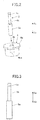
- the constraining part of this embodiment includes an opening 6b for inserting an insertion part 5a of the shaft 5 therethrough as illustrated in Fig. 2 .
- the opening 6b is formed with a closed end by perforating a cylindrical plunger 6 from the side of a flange 6a of the plunger 6.
- the constraining part of this embodiment also includes a bottom 6ba.
- the shaft 5 includes a small diameter part 5b for installing the pressure spring 9 provided in the side of the contacting direction Xa of the insertion part 5a.
- the small diameter part 5b has a diameter smaller than the insertion part 5a as illustrated in Figs. 2 and 3 .
- the shaft 5 also includes a groove 5c formed close to an end of the small diameter part 5b.
- the groove 5c extending in a circumferential direction is formed on an end of the shaft 5 (upper end in Fig. 4 ) in the contacting direction Xa.
- An E-ring (an example of plate part) 10 is engaged to the groove 5c.
- the E-ring 10 functions as an engaging part that engages an end of the recovery spring 8 in the separating direction Xb (lower side in Fig. 4 ).
- a JIS standard E-type retaining ring may be used as the E-ring 10.
- the E-ring 10 includes an inner peripheral part contacting an outer peripheral surface of the groove 5c and an outer peripheral part contacting the end of the recovery spring 8 in the separating direction Xb.
- the electromagnetic relay 1 of the first embodiment includes an insulating barrier 15 that ensures insulation between the yokes 11-13 constituting the driving part 7 and an electric coil wiring 14 as illustrated in Fig. 1 .
- Each of the yokes 11-13 constitutes a part of a magnetic circuit.
- the electromagnetic relay 1 also includes a reel-like bobbin (an example of wound part) 16 around which the electric coil wiring 14 is wound.
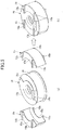
- target engagement parts 16a are formed in two parts of the bobbin 16 as illustrated in (a) of Fig. 5 .
- the target engagement parts 16a have concave sector shapes to be engaged with the insulating barrier 15 at an outer side thereof in its radial direction.
- the insulating barrier 15 includes an engagement part that engages the target engagement part 16a.
- the insulating barrier 15 has a hollow sector-pillar shape that is concaved at an inner side thereof in its radial direction and includes a sector surface 15a forming an engagement part with another sector surface 15a on its opposite side.
- Two insulating barriers 15 are provided for the bobbin 16.
- a pair of planar constraining parts 15b are arranged in parallel on upper and lower surfaces of each insulating barrier 15, so that the bobbin 16 is constrained from moving in a circumferential direction of the bobbin 16 relative to the yokes 11, 13 having a part extending_in a radial direction of the bobbin 16.
- the insulating barriers 15 and the bobbin 16 are formed of, for example, a synthetic resin.
- the pair of sector-shaped target engagement parts 16a are arranged at equal intervals in a circumferential direction of the bobbin 16.
- the four constraining parts 15b on the upper side form a configuration that sandwiches the planar yoke 13 (see Fig. 1 ) therebetween whereas the four constraining parts 15b on the lower side form a configuration that sandwiches the planar U-shaped yoke 11 illustrated in (a) of Fig. 6 .
- the insulation barriers 15 are arranged to be interposed between the electric coil wiring 14 and an area in a circumferential direction of the electromagnetic relay 1 having the yokes 11, 13 extending in this area of the electromagnetic relay 1.
- the electromagnetic relay 1 of the first embodiment includes a driving part housing 17, a contact housing 18, and a connection housing 19 as illustrated in Fig. 1 .
- the driving part housing 17 may be formed of, for example, a mold resin.
- the driving part housing 17 has a close-ended box-like shape for encasing the driving part 7 therein.
- the connection housing 19 and the contact housing 18 may also be formed of, for example, mold resin.
- a cylindrical projection 17a is provided at a bottom of the driving part housing 17.
- a hole 11a having a diameter greater than the diameter of the projecting part 17a is provided in the U-shaped planar yoke 11.
- a groove 17b is also provided in the bottom of the driving part housing 17.
- the groove 17b has a width that is substantially equal to a width W of the yoke 11 and a depth that is less than a thickness T of the yoke 11. In this embodiment, the total dimension of the depth of the groove 17b and the height of the constraining part 15b is adjusted to be less than or equal to the thickness of the yoke 11.
- the projecting part 17a is inserted through the hole 11a and then inserted through an inner periphery of the yoke 12.
- the position of the yoke 12 is defined by the projecting part 17 inserted therethrough, and the position of the yoke 11 is defined in a manner sandwiched between both sidewalls of the groove 17.
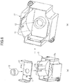
- the bobbin 16 being engaged with the insulation barriers 15 as illustrated in (b) of Fig. 5 is inserted into the driving part housing 17 from above in (b) of Fig. 6 , and the assembly in which the plunger 6 and the shaft 5 are assembled are inserted into the yoke 12.
- the yoke 13 including a hole 13a for inserting the shaft 5 therethrough is mounted on the bobbin 16, and the shaft 5 is inserted through the hole 13a.
- the driving part 7 is assembled.
- a planar connection housing 19 having a shape for engaging the contact housing 18 as illustrated in (a) of Fig. 7 is mounted on the driving part housing 17.
- a trapezoidal protrusion 16b that is formed on the upper side of the bobbin 16 defines the position of the connection housing 19 with respect to the bobbin 16 when mounting the connection housing 19 on the driving part housing 17.
- the pressure spring 9 is inserted through the small diameter part 5b of the shaft 5 in which a hole 4a of the movable element 4 is engaged with the small diameter part 5b.
- the E-ring 10 is engaged with the groove 5c that is formed at the end of the small diameter part 5b, and the end of the recovery spring 8 to the side of the separating direction Xb contacts the outer peripheral part of the E-ring 10.
- the contact housing 18 fixes a pair of columnar fixed terminals 21 each of which having a fixed contact 2 at its end.
- the contact housing 18 is inserted into the driving part housing 17 through an opening of the driving part housing 17, and legs 18a of the contact housing 18 are engaged with the driving part housing 17.
- the fixed contacts 2 are arranged facing the movable contacts 3.
- the contact housing 18 and the driving part housing 17 are hermetically sealed to each other by using an adhesive, welding, or soldering.
- the contact housing 18 includes an installing part 18c for installing a PWM control circuit substrate (drive circuit) 20 that drives the driving part 7.
- the PWM control circuit 20 is provided in an installing space for installing the fixed contact 2 and the movable contact 3 as illustrated in Fig. 8 .
- the fixed terminal 21 corresponds to the fixed contact 2 as illustrated in Fig. 9 .
- the fixed contact 2 is only provided on the end of the fixed terminal 21 at the separating direction Xb and an area facing the movable contact 3.
- the movable element 4 has a planar shape extending in both ways in a radial direction of the shaft 5.
- One movable contact 3 is provided on both ends of the movable element 4, respectively.
- the contact 3 has a hexagonal shape formed by cutting two corners of a longitudinal side of a rectangle.
- the fixed contact 2 has a semi-circular shape that circumscribes the hexagonal contact 3.
- the electromagnetic relay 1 of the first embodiment is a 1-form-X plunger type relay having a pair of contacts as described above.
- a pair of fixed terminals 21 of Fig. 1 is inserted into any part of a direct current circuit to be connected/disconnected, and a terminal of the electric coil wire of the driving part 7 is connected to an input/output interface of the PWM control circuit 20, so that excitation current can be suitably controlled.
- the electromagnetic relay 1 of the first embodiment With the electromagnetic relay 1 of the first embodiment, the following effects can be attained. Owing to the configuration having the insertion part 5a of the shaft 5 inserted into the close-ended opening 6b of the plunger 6, contact between the bottom 6ba and the end of the insertion part 5a can be ensured by using the resilient force of the recovery spring 8 when excitation current is not applied whereas the contact between the bottom 6ba and the end of the insertion part 5a can be ensured by using the electromagnetic force that attracts the plunger 6 in the contacting direction Xa when excitation current is applied. That is, the procedure of securely fixing the shaft 5 and the plunger 6 by welding, using an adhesive, or the like after temporarily fastening the shaft 5 and the plunger 6 can be omitted. Thereby, simplification of the manufacturing process and cost reduction can be achieved.
- Dynamic coupling between the end of the recovery spring 8 to the side of the separating direction Xb and the end of the shaft 5 to the side of the contacting direction Xa can be easily achieved by engaging the groove 5c of the small diameter part 5b of the shaft 5 to a commonly used E-ring 10. That is, the processing procedures such as changing the shape of the end of the small diameter part 5b of the shaft 5 for coupling with the recovery spring 8 or inserting a pin for receiving the end of the shaft 5 into an opening provided in a radial direction of the small diameter part 5b can be omitted.
- the insulating barrier 15 By placing the insulating barrier 15 along the areas in which the yoke 11 and the yoke 13 extend, the insulating performance between the electric coil wire 14 and the magnetic circuit can be enhanced. That is, even if a sufficient insulating distance cannot be obtained due to downsizing of the electromagnetic relay 1, a reliable insulating property can be attained by placing the insulating barrier 15. Further, the constraining part 15b of the insulating barrier 15 defines the positioning between the bobbin 16 and the driving part housing 17 interposed by the yoke 11 and the positioning between the bobbin 16 and the connection housing 19 interposed by the yoke 13. Because a reliable insulating property can be attained, the PWM control unit 20 can be easily installed in the contact housing 18, and centralization of components can be achieved.
- the volume of the material used for forming the fixed contact 2 can be reduced to achieve cost reduction. Particularly, cost reduction can be achieved significantly in a case where a noble metal system is used as the fixed contact 2.
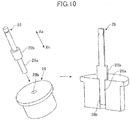
- a constraining part of the second embodiment includes a shaft 25 and a through-hole 26b as illustrated in Fig. 10 .
- the shaft 25 includes an insertion part 25a and a large diameter part 25b having a diameter greater than the diameter of the insertion part 25b.
- the through-hole 26b for inserting the insertion part 25a therethrough is formed by perforating a plunger 26.
- the electromagnetic relay of the second embodiment can ensure contact between an end of the large diameter part 25b toward the separating direction Xb and an surface of the plunger 26 toward the contacting direction Xa by using the resilient force of the recovery spring 8 when excitation current is not applied whereas the contact between the end of the large diameter part 25b and the surface of the plunger 26 can be ensured by using the electromagnetic force that attracts the plunger 26 in the contacting direction Xa when excitation current is applied. That is, similar to the first embodiment, the procedure of securely fixing the shaft 25 and the plunger 26 by welding, using an adhesive, or the like after temporarily fastening the shaft 25 and the plunger 26 can be omitted. Thereby, simplification of the manufacturing process and cost reduction can be achieved.
- the processing of the plunger 26 is easier compared to the processing of the close-ended plunger 6 because the through-hole 26b is formed by simply perforating the plunger 26. Thereby, further cost reduction can be achieved.
- the electromagnetic relay according to the embodiments of the present invention is suitably used for domestic, industrial, and in-vehicle purposes.
Landscapes
- Physics & Mathematics (AREA)
- Electromagnetism (AREA)
- Electromagnets (AREA)
Claims (10)
- Relais électromagnétique (1) comprenant :un contact fixe (2) ;un contact mobile (3) correspondant au contact fixe (2) ;un élément mobile (4) qui retient le contact mobile (3) et se déplace dans une direction de contact (Xa) lorsque le courant d'excitation est appliqué et une direction de séparation (Xb) lorsque le courant d'excitation n'est pas appliqué par rapport au contact fixe (2) ;un noyau axial (5) comprenant une partie d'insertion (5a), le noyau axial (5) étant couplé à l'élément mobile (4) ;un noyau mobile (6) comprenant une partie de contrainte comprenant une ouverture à extrémité fermée (6b) pour insérer le noyau axial (5) à travers cette dernière qui a un fond (6ba), le noyau mobile (6) étant couplé au noyau axial (5) pour se déplacer dans la direction de contact (Xa) et la direction de séparation (Xb) par rapport à un mouvement du noyau axial (5) ;une partie d'entraînement (7) qui entraîne le noyau mobile (6) dans la direction de contact (Xa) ;une partie de poussée (8) qui exerce une force sur le noyau axial (5) dans la direction de séparation (Xb) ;caractérisé en ce que :
la partie de contrainte contraint le mouvement relatif du noyau axial (5) dans la direction de séparation (Xb) afin de garantir le contact entre la partie d'insertion (5a) et le fond (6ba) de l'ouverture à extrémité fermée (6b) du noyau mobile (6) lorsque le courant d'excitation n'est pas appliqué. - Relais électromagnétique (1) comprenant :un contact fixe (2) ;un contact mobile (3) correspondant au contact fixe (2) ;un élément mobile (4) qui retient le contact mobile (3) et se déplace dans une direction de contact (Xa) lorsque le courant d'excitation est appliqué et une direction de séparation (Xb) lorsque le courant d'excitation n'est pas appliqué par rapport au contact fixe (2) ;un noyau mobile (6) comprenant une partie de contrainte comprenant un trou traversant (26b) ;un noyau axial (5) comprenant une partie d'insertion (25a) à insérer dans le trou débouchant (26b) et une partie de grand diamètre (25b) ayant un diamètre supérieur à un diamètre de la partie d'insertion (25a), dans lequel le noyau axial (5) est couplé à l'élément mobile (4) et le noyau mobile (6) est couplé au noyau axial (5) pour se déplacer dans la direction de contact (Xa) et la direction de séparation (Xb) par rapport à un mouvement du noyau axial (5) ;une partie d'entraînement (7) qui entraîne le noyau mobile (6) dans la direction de contact (Xa) ;une partie de poussée (8) qui exerce une force sur le noyau axial (5) dans la direction de séparation (Xb) ;caractérisé en ce que :
la partie de contrainte contraint le mouvement relatif du noyau axial (5) dans la direction de séparation (Xb) afin de garantir le contact entre une extrémité de la partie de grand diamètre (25b) vers la direction de séparation (Xb) et une surface du noyau mobile (6) vers la direction de contact (Xa) lorsque le courant d'excitation n'est pas appliqué. - Relais électromagnétique (1) selon les revendications 1 ou 2,
dans lequel le noyau axial (5) a une extrémité couplée au noyau mobile (6) et une autre extrémité sur un côté opposé de la une extrémité, et
dans lequel le noyau axial (5) a une partie de mise en prise sur l'autre extrémité pour mettre en prise la partie de poussée (8). - Relais électromagnétique (1) selon la revendication 3,
dans lequel le noyau axial (5) comprend une rainure (5c) prévue sur l'autre extrémité, et
dans lequel la partie de mise en prise comprend une plaque (10) qui met en prise la rainure (5c). - Relais électromagnétique (1) selon les revendications 1 ou 2,
dans lequel la partie d'entraînement (7) comprend :une culasse (11, 12, 13),un câblage de bobine électrique (14), etune barrière isolante (15) qui isole la culasse (11, 12, 13) et le câblage de bobine électrique (14). - Relais électromagnétique (1) selon la revendication 5,
dans lequel la partie d'entraînement (7) comprend en outre une partie enroulée (16) autour de laquelle le câblage de bobine électrique (14) est enroulé,
dans lequel la partie enroulée (16) comprend une partie de mise en prise cible (16a) par rapport à laquelle la barrière isolante (15) est mise en prise, et
dans lequel la barrière isolante (15) comprend une partie de mise en prise pour mettre en prise la partie de mise en prise cible (16a). - Relais électromagnétique (1) selon la revendication 6,
dans lequel la barrière isolante (15) a une forme de pilier à secteur creux et comprend une partie de surface de secteur (15a). - Relais électromagnétique (1) selon la revendication 7,
dans lequel la culasse (11, 12, 13) comprend une partie d'extension s'étendant dans une direction radiale de la partie enroulée (16), et
dans lequel la barrière isolante (15) comprend une partie contrainte qui contraint un mouvement de la partie d'extension par rapport à une direction circonférentielle de la partie enroulée (16). - Relais électromagnétique (1) selon les revendications 1 ou 2,
dans lequel la partie d'entraînement (7) comprend en outre un circuit d'entraînement (20) pour entraîner la partie d'entraînement, et
dans lequel le circuit d'entraînement (20) est agencé dans un espace d'installation pour installer le contact fixe (2) et le contact mobile (3). - Relais électromagnétique (1) selon les revendications 1 ou 2,
dans lequel l'élément mobile (4) a une forme de plaque s'étendant dans une direction radiale du noyau axial (5),
dans lequel le contact mobile (3) est prévu sur les deux extrémités de l'élément mobile (4).
Applications Claiming Priority (2)
| Application Number | Priority Date | Filing Date | Title |
|---|---|---|---|
| JP2012208950A JP6071376B2 (ja) | 2012-09-21 | 2012-09-21 | 電磁継電器 |
| PCT/JP2013/075089 WO2014046104A1 (fr) | 2012-09-21 | 2013-09-18 | Relais électromagnétique |
Publications (3)
| Publication Number | Publication Date |
|---|---|
| EP2899736A1 EP2899736A1 (fr) | 2015-07-29 |
| EP2899736A4 EP2899736A4 (fr) | 2016-05-11 |
| EP2899736B1 true EP2899736B1 (fr) | 2018-08-01 |
Family
ID=50341414
Family Applications (1)
| Application Number | Title | Priority Date | Filing Date |
|---|---|---|---|
| EP13839873.0A Not-in-force EP2899736B1 (fr) | 2012-09-21 | 2013-09-18 | Relais électromagnétique |
Country Status (6)
| Country | Link |
|---|---|
| US (1) | US9793079B2 (fr) |
| EP (1) | EP2899736B1 (fr) |
| JP (1) | JP6071376B2 (fr) |
| KR (1) | KR101802617B1 (fr) |
| CN (1) | CN104641441B (fr) |
| WO (1) | WO2014046104A1 (fr) |
Cited By (1)
| Publication number | Priority date | Publication date | Assignee | Title |
|---|---|---|---|---|
| RU192146U1 (ru) * | 2019-03-21 | 2019-09-05 | Елена Евгеньевна Кашичкина | Траверса |
Families Citing this family (18)
| Publication number | Priority date | Publication date | Assignee | Title |
|---|---|---|---|---|
| CN108417448B (zh) * | 2013-06-28 | 2021-03-05 | 松下知识产权经营株式会社 | 触点装置以及搭载有该触点装置的电磁继电器 |
| JP6433706B2 (ja) | 2014-07-28 | 2018-12-05 | 富士通コンポーネント株式会社 | 電磁継電器及びコイル端子 |
| WO2016038769A1 (fr) * | 2014-09-10 | 2016-03-17 | 富士電機機器制御株式会社 | Appareil à contact électromagnétique |
| US9916952B2 (en) * | 2015-06-12 | 2018-03-13 | Te Connectivity Corporation | Carrier sub-assembly for an electrical relay device |
| KR101943365B1 (ko) * | 2015-10-14 | 2019-01-29 | 엘에스산전 주식회사 | 직류 릴레이 |
| EP3184804A1 (fr) * | 2015-12-22 | 2017-06-28 | Mahle International GmbH | Entraînement de solénoïde destiné à un démarreur pour un moteur à combustion interne |
| CN105719910B (zh) * | 2016-04-29 | 2017-11-10 | 浙江英洛华新能源科技有限公司 | 高压直流继电器磁路系统 |
| JP7143679B2 (ja) * | 2018-08-28 | 2022-09-29 | オムロン株式会社 | 電磁継電器 |
| JP7135590B2 (ja) | 2018-08-28 | 2022-09-13 | オムロン株式会社 | 電磁継電器 |
| KR102097642B1 (ko) * | 2018-11-13 | 2020-04-06 | 엘에스산전 주식회사 | 직류 릴레이 |
| KR102340034B1 (ko) * | 2019-05-29 | 2021-12-16 | 엘에스일렉트릭 (주) | 직류 릴레이 |
| JP7351155B2 (ja) * | 2019-09-13 | 2023-09-27 | オムロン株式会社 | 電磁継電器 |
| JP7351157B2 (ja) * | 2019-09-18 | 2023-09-27 | オムロン株式会社 | リレー |
| JP7451910B2 (ja) * | 2019-09-18 | 2024-03-19 | オムロン株式会社 | リレー |
| CN112271110A (zh) * | 2020-10-14 | 2021-01-26 | 旭格威科技(上海)有限公司 | 一种节能无极性直流接触器 |
| JP7586003B2 (ja) * | 2021-07-08 | 2024-11-19 | 富士電機機器制御株式会社 | 非磁性板、電磁接触器、非磁性素材、および製造方法 |
| JP7699487B2 (ja) * | 2021-07-16 | 2025-06-27 | Fclコンポーネント株式会社 | リレー |
| CN118675944A (zh) * | 2023-03-17 | 2024-09-20 | 厦门宏发电力电器有限公司 | 一种继电器 |
Citations (1)
| Publication number | Priority date | Publication date | Assignee | Title |
|---|---|---|---|---|
| EP2093786A1 (fr) * | 2008-02-20 | 2009-08-26 | Denso Corporation | Commutateur solénoïde de démarreur avec agencement amélioré de résistance |
Family Cites Families (17)
| Publication number | Priority date | Publication date | Assignee | Title |
|---|---|---|---|---|
| GB1441940A (en) * | 1972-11-29 | 1976-07-07 | Siemens Ag | Electromagnetic relays |
| JPS562337Y2 (fr) * | 1976-07-02 | 1981-01-20 | ||
| JPS60192828A (ja) | 1984-03-13 | 1985-10-01 | Mazda Motor Corp | 過給機付エンジン |
| DE3506354C1 (de) * | 1985-02-22 | 1986-03-27 | Siemens AG, 1000 Berlin und 8000 München | Elektromagnetisches Relais mit Isolierkappe und Verfahren zur Herstellung der Isolierkappe |
| US5892194A (en) * | 1996-03-26 | 1999-04-06 | Matsushita Electric Works, Ltd. | Sealed contact device with contact gap adjustment capability |
| JP2000322999A (ja) * | 1999-05-12 | 2000-11-24 | Mitsubishi Electric Corp | スタータ用マグネットスイッチ |
| FR2798506B1 (fr) * | 1999-09-15 | 2001-11-09 | Schneider Electric Ind Sa | Actionneur electromagnetique muni de deux ressorts de rappel |
| JP4078820B2 (ja) * | 2001-09-21 | 2008-04-23 | オムロン株式会社 | 封止接点装置 |
| KR100505438B1 (ko) * | 2001-11-29 | 2005-07-29 | 마츠시다 덴코 가부시키가이샤 | 전자(電磁) 개폐 장치 |
| JP2003184710A (ja) * | 2001-12-13 | 2003-07-03 | Denso Corp | スタータ用電磁スイッチ |
| JP2005026182A (ja) * | 2003-07-02 | 2005-01-27 | Matsushita Electric Works Ltd | 電磁開閉装置 |
| WO2006104080A1 (fr) * | 2005-03-28 | 2006-10-05 | Matsushita Electric Works, Ltd. | Dispositif de contacts |
| CN101677044B (zh) * | 2008-09-19 | 2011-12-28 | 厦门宏发电力电器有限公司 | 一种高可靠长寿命的高压直流真空继电器 |
| US8581682B2 (en) * | 2009-10-07 | 2013-11-12 | Tyco Electronics Corporation | Magnet aided solenoid for an electrical switch |
| JP5569349B2 (ja) * | 2009-12-11 | 2014-08-13 | 株式会社デンソー | 電磁継電器 |
| CN201608110U (zh) * | 2010-01-04 | 2010-10-13 | 宁波天波纬业电器有限公司 | 大功率继电器 |
| JP5504899B2 (ja) * | 2010-01-12 | 2014-05-28 | 株式会社デンソー | 電磁継電器 |
-
2012
- 2012-09-21 JP JP2012208950A patent/JP6071376B2/ja not_active Expired - Fee Related
-
2013
- 2013-09-18 KR KR1020157006663A patent/KR101802617B1/ko not_active Expired - Fee Related
- 2013-09-18 WO PCT/JP2013/075089 patent/WO2014046104A1/fr not_active Ceased
- 2013-09-18 CN CN201380048438.0A patent/CN104641441B/zh not_active Expired - Fee Related
- 2013-09-18 EP EP13839873.0A patent/EP2899736B1/fr not_active Not-in-force
-
2015
- 2015-03-17 US US14/659,728 patent/US9793079B2/en not_active Expired - Fee Related
Patent Citations (1)
| Publication number | Priority date | Publication date | Assignee | Title |
|---|---|---|---|---|
| EP2093786A1 (fr) * | 2008-02-20 | 2009-08-26 | Denso Corporation | Commutateur solénoïde de démarreur avec agencement amélioré de résistance |
Cited By (1)
| Publication number | Priority date | Publication date | Assignee | Title |
|---|---|---|---|---|
| RU192146U1 (ru) * | 2019-03-21 | 2019-09-05 | Елена Евгеньевна Кашичкина | Траверса |
Also Published As
| Publication number | Publication date |
|---|---|
| KR20150044929A (ko) | 2015-04-27 |
| KR101802617B1 (ko) | 2017-11-28 |
| EP2899736A1 (fr) | 2015-07-29 |
| EP2899736A4 (fr) | 2016-05-11 |
| WO2014046104A1 (fr) | 2014-03-27 |
| JP6071376B2 (ja) | 2017-02-01 |
| JP2014063674A (ja) | 2014-04-10 |
| US9793079B2 (en) | 2017-10-17 |
| US20150187527A1 (en) | 2015-07-02 |
| CN104641441A (zh) | 2015-05-20 |
| CN104641441B (zh) | 2017-07-11 |
Similar Documents
| Publication | Publication Date | Title |
|---|---|---|
| EP2899736B1 (fr) | Relais électromagnétique | |
| EP3264437B1 (fr) | Relais électromagnétique | |
| KR101661396B1 (ko) | 전자기 릴레이 | |
| US8237524B2 (en) | Electromagnetic switching device | |
| JP6003740B2 (ja) | 電磁継電器 | |
| US9299520B2 (en) | Electromagnetic relay | |
| JP6287727B2 (ja) | 電磁継電器 | |
| JP5594184B2 (ja) | 電磁スイッチ装置 | |
| US9030059B2 (en) | Actuator | |
| WO2009139367A1 (fr) | Relais électromagnétique | |
| JP2006286258A (ja) | スタータ用電磁スイッチ | |
| JP4840386B2 (ja) | 接点装置 | |
| JP6107110B2 (ja) | 電磁リレー | |
| KR20250157239A (ko) | 전기 디바이스를 위한 가동 캐리어 구조 | |
| JP2009211831A (ja) | リレー | |
| JP6003771B2 (ja) | 電磁継電器 | |
| KR101974970B1 (ko) | 전자 접촉기 | |
| WO2014132522A1 (fr) | Dispositif de démarrage de moteur | |
| JP5281137B2 (ja) | 常閉接点式電磁リレーおよびそれを用いた車載用電磁機器 | |
| JP2019053922A (ja) | リレー装置およびリレー装置とリレーボックスとの接続構造 | |
| JP2008041336A (ja) | 電磁リレー | |
| JP2004247199A (ja) | スタータ用電磁スイッチ |
Legal Events
| Date | Code | Title | Description |
|---|---|---|---|
| PUAI | Public reference made under article 153(3) epc to a published international application that has entered the european phase |
Free format text: ORIGINAL CODE: 0009012 |
|
| 17P | Request for examination filed |
Effective date: 20150319 |
|
| AK | Designated contracting states |
Kind code of ref document: A1 Designated state(s): AL AT BE BG CH CY CZ DE DK EE ES FI FR GB GR HR HU IE IS IT LI LT LU LV MC MK MT NL NO PL PT RO RS SE SI SK SM TR |
|
| AX | Request for extension of the european patent |
Extension state: BA ME |
|
| DAX | Request for extension of the european patent (deleted) | ||
| RIC1 | Information provided on ipc code assigned before grant |
Ipc: H01H 50/54 20060101ALI20160324BHEP Ipc: H01H 50/44 20060101ALI20160324BHEP Ipc: H01H 50/10 20060101ALI20160324BHEP Ipc: H01H 50/20 20060101AFI20160324BHEP Ipc: H01H 50/04 20060101ALI20160324BHEP Ipc: H01H 50/02 20060101ALI20160324BHEP |
|
| RA4 | Supplementary search report drawn up and despatched (corrected) |
Effective date: 20160412 |
|
| GRAP | Despatch of communication of intention to grant a patent |
Free format text: ORIGINAL CODE: EPIDOSNIGR1 |
|
| STAA | Information on the status of an ep patent application or granted ep patent |
Free format text: STATUS: GRANT OF PATENT IS INTENDED |
|
| RIC1 | Information provided on ipc code assigned before grant |
Ipc: H01H 50/20 20060101AFI20180209BHEP Ipc: H01H 50/10 20060101ALI20180209BHEP Ipc: H01H 50/54 20060101ALI20180209BHEP Ipc: H01H 50/44 20060101ALI20180209BHEP Ipc: H01H 50/04 20060101ALI20180209BHEP Ipc: H01H 50/02 20060101ALI20180209BHEP |
|
| INTG | Intention to grant announced |
Effective date: 20180308 |
|
| GRAS | Grant fee paid |
Free format text: ORIGINAL CODE: EPIDOSNIGR3 |
|
| GRAA | (expected) grant |
Free format text: ORIGINAL CODE: 0009210 |
|
| STAA | Information on the status of an ep patent application or granted ep patent |
Free format text: STATUS: THE PATENT HAS BEEN GRANTED |
|
| AK | Designated contracting states |
Kind code of ref document: B1 Designated state(s): AL AT BE BG CH CY CZ DE DK EE ES FI FR GB GR HR HU IE IS IT LI LT LU LV MC MK MT NL NO PL PT RO RS SE SI SK SM TR |
|
| REG | Reference to a national code |
Ref country code: GB Ref legal event code: FG4D |
|
| REG | Reference to a national code |
Ref country code: FR Ref legal event code: PLFP Year of fee payment: 6 |
|
| REG | Reference to a national code |
Ref country code: CH Ref legal event code: EP Ref country code: AT Ref legal event code: REF Ref document number: 1025298 Country of ref document: AT Kind code of ref document: T Effective date: 20180815 |
|
| REG | Reference to a national code |
Ref country code: IE Ref legal event code: FG4D |
|
| REG | Reference to a national code |
Ref country code: DE Ref legal event code: R096 Ref document number: 602013041343 Country of ref document: DE |
|
| PGFP | Annual fee paid to national office [announced via postgrant information from national office to epo] |
Ref country code: DE Payment date: 20180921 Year of fee payment: 6 Ref country code: FR Payment date: 20180810 Year of fee payment: 6 |
|
| REG | Reference to a national code |
Ref country code: NL Ref legal event code: MP Effective date: 20180801 |
|
| REG | Reference to a national code |
Ref country code: LT Ref legal event code: MG4D |
|
| REG | Reference to a national code |
Ref country code: AT Ref legal event code: MK05 Ref document number: 1025298 Country of ref document: AT Kind code of ref document: T Effective date: 20180801 |
|
| PG25 | Lapsed in a contracting state [announced via postgrant information from national office to epo] |
Ref country code: FI Free format text: LAPSE BECAUSE OF FAILURE TO SUBMIT A TRANSLATION OF THE DESCRIPTION OR TO PAY THE FEE WITHIN THE PRESCRIBED TIME-LIMIT Effective date: 20180801 Ref country code: RS Free format text: LAPSE BECAUSE OF FAILURE TO SUBMIT A TRANSLATION OF THE DESCRIPTION OR TO PAY THE FEE WITHIN THE PRESCRIBED TIME-LIMIT Effective date: 20180801 Ref country code: IS Free format text: LAPSE BECAUSE OF FAILURE TO SUBMIT A TRANSLATION OF THE DESCRIPTION OR TO PAY THE FEE WITHIN THE PRESCRIBED TIME-LIMIT Effective date: 20181201 Ref country code: AT Free format text: LAPSE BECAUSE OF FAILURE TO SUBMIT A TRANSLATION OF THE DESCRIPTION OR TO PAY THE FEE WITHIN THE PRESCRIBED TIME-LIMIT Effective date: 20180801 Ref country code: BG Free format text: LAPSE BECAUSE OF FAILURE TO SUBMIT A TRANSLATION OF THE DESCRIPTION OR TO PAY THE FEE WITHIN THE PRESCRIBED TIME-LIMIT Effective date: 20181101 Ref country code: NO Free format text: LAPSE BECAUSE OF FAILURE TO SUBMIT A TRANSLATION OF THE DESCRIPTION OR TO PAY THE FEE WITHIN THE PRESCRIBED TIME-LIMIT Effective date: 20181101 Ref country code: SE Free format text: LAPSE BECAUSE OF FAILURE TO SUBMIT A TRANSLATION OF THE DESCRIPTION OR TO PAY THE FEE WITHIN THE PRESCRIBED TIME-LIMIT Effective date: 20180801 Ref country code: GR Free format text: LAPSE BECAUSE OF FAILURE TO SUBMIT A TRANSLATION OF THE DESCRIPTION OR TO PAY THE FEE WITHIN THE PRESCRIBED TIME-LIMIT Effective date: 20181102 Ref country code: NL Free format text: LAPSE BECAUSE OF FAILURE TO SUBMIT A TRANSLATION OF THE DESCRIPTION OR TO PAY THE FEE WITHIN THE PRESCRIBED TIME-LIMIT Effective date: 20180801 Ref country code: PL Free format text: LAPSE BECAUSE OF FAILURE TO SUBMIT A TRANSLATION OF THE DESCRIPTION OR TO PAY THE FEE WITHIN THE PRESCRIBED TIME-LIMIT Effective date: 20180801 Ref country code: LT Free format text: LAPSE BECAUSE OF FAILURE TO SUBMIT A TRANSLATION OF THE DESCRIPTION OR TO PAY THE FEE WITHIN THE PRESCRIBED TIME-LIMIT Effective date: 20180801 |
|
| PG25 | Lapsed in a contracting state [announced via postgrant information from national office to epo] |
Ref country code: AL Free format text: LAPSE BECAUSE OF FAILURE TO SUBMIT A TRANSLATION OF THE DESCRIPTION OR TO PAY THE FEE WITHIN THE PRESCRIBED TIME-LIMIT Effective date: 20180801 Ref country code: LV Free format text: LAPSE BECAUSE OF FAILURE TO SUBMIT A TRANSLATION OF THE DESCRIPTION OR TO PAY THE FEE WITHIN THE PRESCRIBED TIME-LIMIT Effective date: 20180801 Ref country code: HR Free format text: LAPSE BECAUSE OF FAILURE TO SUBMIT A TRANSLATION OF THE DESCRIPTION OR TO PAY THE FEE WITHIN THE PRESCRIBED TIME-LIMIT Effective date: 20180801 |
|
| PGFP | Annual fee paid to national office [announced via postgrant information from national office to epo] |
Ref country code: GB Payment date: 20181127 Year of fee payment: 6 |
|
| PG25 | Lapsed in a contracting state [announced via postgrant information from national office to epo] |
Ref country code: MC Free format text: LAPSE BECAUSE OF FAILURE TO SUBMIT A TRANSLATION OF THE DESCRIPTION OR TO PAY THE FEE WITHIN THE PRESCRIBED TIME-LIMIT Effective date: 20180801 Ref country code: ES Free format text: LAPSE BECAUSE OF FAILURE TO SUBMIT A TRANSLATION OF THE DESCRIPTION OR TO PAY THE FEE WITHIN THE PRESCRIBED TIME-LIMIT Effective date: 20180801 Ref country code: CZ Free format text: LAPSE BECAUSE OF FAILURE TO SUBMIT A TRANSLATION OF THE DESCRIPTION OR TO PAY THE FEE WITHIN THE PRESCRIBED TIME-LIMIT Effective date: 20180801 Ref country code: IT Free format text: LAPSE BECAUSE OF FAILURE TO SUBMIT A TRANSLATION OF THE DESCRIPTION OR TO PAY THE FEE WITHIN THE PRESCRIBED TIME-LIMIT Effective date: 20180801 Ref country code: RO Free format text: LAPSE BECAUSE OF FAILURE TO SUBMIT A TRANSLATION OF THE DESCRIPTION OR TO PAY THE FEE WITHIN THE PRESCRIBED TIME-LIMIT Effective date: 20180801 Ref country code: EE Free format text: LAPSE BECAUSE OF FAILURE TO SUBMIT A TRANSLATION OF THE DESCRIPTION OR TO PAY THE FEE WITHIN THE PRESCRIBED TIME-LIMIT Effective date: 20180801 |
|
| REG | Reference to a national code |
Ref country code: CH Ref legal event code: PL |
|
| REG | Reference to a national code |
Ref country code: DE Ref legal event code: R097 Ref document number: 602013041343 Country of ref document: DE |
|
| PG25 | Lapsed in a contracting state [announced via postgrant information from national office to epo] |
Ref country code: DK Free format text: LAPSE BECAUSE OF FAILURE TO SUBMIT A TRANSLATION OF THE DESCRIPTION OR TO PAY THE FEE WITHIN THE PRESCRIBED TIME-LIMIT Effective date: 20180801 Ref country code: SM Free format text: LAPSE BECAUSE OF FAILURE TO SUBMIT A TRANSLATION OF THE DESCRIPTION OR TO PAY THE FEE WITHIN THE PRESCRIBED TIME-LIMIT Effective date: 20180801 Ref country code: SK Free format text: LAPSE BECAUSE OF FAILURE TO SUBMIT A TRANSLATION OF THE DESCRIPTION OR TO PAY THE FEE WITHIN THE PRESCRIBED TIME-LIMIT Effective date: 20180801 |
|
| PLBE | No opposition filed within time limit |
Free format text: ORIGINAL CODE: 0009261 |
|
| STAA | Information on the status of an ep patent application or granted ep patent |
Free format text: STATUS: NO OPPOSITION FILED WITHIN TIME LIMIT |
|
| REG | Reference to a national code |
Ref country code: BE Ref legal event code: MM Effective date: 20180930 |
|
| REG | Reference to a national code |
Ref country code: IE Ref legal event code: MM4A |
|
| PG25 | Lapsed in a contracting state [announced via postgrant information from national office to epo] |
Ref country code: LU Free format text: LAPSE BECAUSE OF NON-PAYMENT OF DUE FEES Effective date: 20180918 |
|
| 26N | No opposition filed |
Effective date: 20190503 |
|
| PG25 | Lapsed in a contracting state [announced via postgrant information from national office to epo] |
Ref country code: IE Free format text: LAPSE BECAUSE OF NON-PAYMENT OF DUE FEES Effective date: 20180918 |
|
| PG25 | Lapsed in a contracting state [announced via postgrant information from national office to epo] |
Ref country code: SI Free format text: LAPSE BECAUSE OF FAILURE TO SUBMIT A TRANSLATION OF THE DESCRIPTION OR TO PAY THE FEE WITHIN THE PRESCRIBED TIME-LIMIT Effective date: 20180801 Ref country code: CH Free format text: LAPSE BECAUSE OF NON-PAYMENT OF DUE FEES Effective date: 20180930 Ref country code: LI Free format text: LAPSE BECAUSE OF NON-PAYMENT OF DUE FEES Effective date: 20180930 Ref country code: BE Free format text: LAPSE BECAUSE OF NON-PAYMENT OF DUE FEES Effective date: 20180930 |
|
| PG25 | Lapsed in a contracting state [announced via postgrant information from national office to epo] |
Ref country code: MT Free format text: LAPSE BECAUSE OF NON-PAYMENT OF DUE FEES Effective date: 20180918 |
|
| PG25 | Lapsed in a contracting state [announced via postgrant information from national office to epo] |
Ref country code: TR Free format text: LAPSE BECAUSE OF FAILURE TO SUBMIT A TRANSLATION OF THE DESCRIPTION OR TO PAY THE FEE WITHIN THE PRESCRIBED TIME-LIMIT Effective date: 20180801 |
|
| REG | Reference to a national code |
Ref country code: DE Ref legal event code: R119 Ref document number: 602013041343 Country of ref document: DE |
|
| PG25 | Lapsed in a contracting state [announced via postgrant information from national office to epo] |
Ref country code: PT Free format text: LAPSE BECAUSE OF FAILURE TO SUBMIT A TRANSLATION OF THE DESCRIPTION OR TO PAY THE FEE WITHIN THE PRESCRIBED TIME-LIMIT Effective date: 20180801 |
|
| PG25 | Lapsed in a contracting state [announced via postgrant information from national office to epo] |
Ref country code: CY Free format text: LAPSE BECAUSE OF FAILURE TO SUBMIT A TRANSLATION OF THE DESCRIPTION OR TO PAY THE FEE WITHIN THE PRESCRIBED TIME-LIMIT Effective date: 20180801 Ref country code: HU Free format text: LAPSE BECAUSE OF FAILURE TO SUBMIT A TRANSLATION OF THE DESCRIPTION OR TO PAY THE FEE WITHIN THE PRESCRIBED TIME-LIMIT; INVALID AB INITIO Effective date: 20130918 Ref country code: MK Free format text: LAPSE BECAUSE OF NON-PAYMENT OF DUE FEES Effective date: 20180801 |
|
| PG25 | Lapsed in a contracting state [announced via postgrant information from national office to epo] |
Ref country code: DE Free format text: LAPSE BECAUSE OF NON-PAYMENT OF DUE FEES Effective date: 20200401 |
|
| GBPC | Gb: european patent ceased through non-payment of renewal fee |
Effective date: 20190918 |
|
| PG25 | Lapsed in a contracting state [announced via postgrant information from national office to epo] |
Ref country code: FR Free format text: LAPSE BECAUSE OF NON-PAYMENT OF DUE FEES Effective date: 20190930 Ref country code: GB Free format text: LAPSE BECAUSE OF NON-PAYMENT OF DUE FEES Effective date: 20190918 |