EP2899787A1 - Brennstoffzellenmodul - Google Patents
Brennstoffzellenmodul Download PDFInfo
- Publication number
- EP2899787A1 EP2899787A1 EP14199970.6A EP14199970A EP2899787A1 EP 2899787 A1 EP2899787 A1 EP 2899787A1 EP 14199970 A EP14199970 A EP 14199970A EP 2899787 A1 EP2899787 A1 EP 2899787A1
- Authority
- EP
- European Patent Office
- Prior art keywords
- cylindrical member
- fuel cell
- flow passage
- side wall
- opening portion
- Prior art date
- Legal status (The legal status is an assumption and is not a legal conclusion. Google has not performed a legal analysis and makes no representation as to the accuracy of the status listed.)
- Granted
Links
Images



Classifications
-
- H—ELECTRICITY
- H01—ELECTRIC ELEMENTS
- H01M—PROCESSES OR MEANS, e.g. BATTERIES, FOR THE DIRECT CONVERSION OF CHEMICAL ENERGY INTO ELECTRICAL ENERGY
- H01M8/00—Fuel cells; Manufacture thereof
- H01M8/02—Details
- H01M8/0297—Arrangements for joining electrodes, reservoir layers, heat exchange units or bipolar separators to each other
-
- H—ELECTRICITY
- H01—ELECTRIC ELEMENTS
- H01M—PROCESSES OR MEANS, e.g. BATTERIES, FOR THE DIRECT CONVERSION OF CHEMICAL ENERGY INTO ELECTRICAL ENERGY
- H01M8/00—Fuel cells; Manufacture thereof
- H01M8/04—Auxiliary arrangements, e.g. for control of pressure or for circulation of fluids
- H01M8/04007—Auxiliary arrangements, e.g. for control of pressure or for circulation of fluids related to heat exchange
-
- H—ELECTRICITY
- H01—ELECTRIC ELEMENTS
- H01M—PROCESSES OR MEANS, e.g. BATTERIES, FOR THE DIRECT CONVERSION OF CHEMICAL ENERGY INTO ELECTRICAL ENERGY
- H01M8/00—Fuel cells; Manufacture thereof
- H01M8/04—Auxiliary arrangements, e.g. for control of pressure or for circulation of fluids
- H01M8/04007—Auxiliary arrangements, e.g. for control of pressure or for circulation of fluids related to heat exchange
- H01M8/04067—Heat exchange or temperature measuring elements, thermal insulation, e.g. heat pipes, heat pumps, fins
- H01M8/04074—Heat exchange unit structures specially adapted for fuel cell
-
- H—ELECTRICITY
- H01—ELECTRIC ELEMENTS
- H01M—PROCESSES OR MEANS, e.g. BATTERIES, FOR THE DIRECT CONVERSION OF CHEMICAL ENERGY INTO ELECTRICAL ENERGY
- H01M8/00—Fuel cells; Manufacture thereof
- H01M8/06—Combination of fuel cells with means for production of reactants or for treatment of residues
- H01M8/0606—Combination of fuel cells with means for production of reactants or for treatment of residues with means for production of gaseous reactants
- H01M8/0612—Combination of fuel cells with means for production of reactants or for treatment of residues with means for production of gaseous reactants from carbon-containing material
- H01M8/0625—Combination of fuel cells with means for production of reactants or for treatment of residues with means for production of gaseous reactants from carbon-containing material in a modular combined reactor/fuel cell structure
- H01M8/0631—Reactor construction specially adapted for combination reactor/fuel cell
-
- H—ELECTRICITY
- H01—ELECTRIC ELEMENTS
- H01M—PROCESSES OR MEANS, e.g. BATTERIES, FOR THE DIRECT CONVERSION OF CHEMICAL ENERGY INTO ELECTRICAL ENERGY
- H01M8/00—Fuel cells; Manufacture thereof
- H01M8/24—Grouping of fuel cells, e.g. stacking of fuel cells
- H01M8/241—Grouping of fuel cells, e.g. stacking of fuel cells with solid or matrix-supported electrolytes
- H01M8/2425—High-temperature cells with solid electrolytes
- H01M8/243—Grouping of unit cells of tubular or cylindrical configuration
-
- H—ELECTRICITY
- H01—ELECTRIC ELEMENTS
- H01M—PROCESSES OR MEANS, e.g. BATTERIES, FOR THE DIRECT CONVERSION OF CHEMICAL ENERGY INTO ELECTRICAL ENERGY
- H01M8/00—Fuel cells; Manufacture thereof
- H01M8/24—Grouping of fuel cells, e.g. stacking of fuel cells
- H01M8/2465—Details of groupings of fuel cells
- H01M8/247—Arrangements for tightening a stack, for accommodation of a stack in a tank or for assembling different tanks
- H01M8/2475—Enclosures, casings or containers of fuel cell stacks
-
- H—ELECTRICITY
- H01—ELECTRIC ELEMENTS
- H01M—PROCESSES OR MEANS, e.g. BATTERIES, FOR THE DIRECT CONVERSION OF CHEMICAL ENERGY INTO ELECTRICAL ENERGY
- H01M8/00—Fuel cells; Manufacture thereof
- H01M8/24—Grouping of fuel cells, e.g. stacking of fuel cells
- H01M8/2465—Details of groupings of fuel cells
- H01M8/2484—Details of groupings of fuel cells characterised by external manifolds
-
- H—ELECTRICITY
- H01—ELECTRIC ELEMENTS
- H01M—PROCESSES OR MEANS, e.g. BATTERIES, FOR THE DIRECT CONVERSION OF CHEMICAL ENERGY INTO ELECTRICAL ENERGY
- H01M8/00—Fuel cells; Manufacture thereof
- H01M8/10—Fuel cells with solid electrolytes
- H01M8/12—Fuel cells with solid electrolytes operating at high temperature, e.g. with stabilised ZrO2 electrolyte
- H01M2008/1293—Fuel cells with solid oxide electrolytes
-
- H—ELECTRICITY
- H01—ELECTRIC ELEMENTS
- H01M—PROCESSES OR MEANS, e.g. BATTERIES, FOR THE DIRECT CONVERSION OF CHEMICAL ENERGY INTO ELECTRICAL ENERGY
- H01M8/00—Fuel cells; Manufacture thereof
- H01M8/04—Auxiliary arrangements, e.g. for control of pressure or for circulation of fluids
- H01M8/04007—Auxiliary arrangements, e.g. for control of pressure or for circulation of fluids related to heat exchange
- H01M8/04014—Heat exchange using gaseous fluids; Heat exchange by combustion of reactants
- H01M8/04022—Heating by combustion
-
- H—ELECTRICITY
- H01—ELECTRIC ELEMENTS
- H01M—PROCESSES OR MEANS, e.g. BATTERIES, FOR THE DIRECT CONVERSION OF CHEMICAL ENERGY INTO ELECTRICAL ENERGY
- H01M8/00—Fuel cells; Manufacture thereof
- H01M8/24—Grouping of fuel cells, e.g. stacking of fuel cells
- H01M8/241—Grouping of fuel cells, e.g. stacking of fuel cells with solid or matrix-supported electrolytes
- H01M8/2425—High-temperature cells with solid electrolytes
- H01M8/2428—Grouping by arranging unit cells on a surface of any form, e.g. planar or tubular
-
- Y—GENERAL TAGGING OF NEW TECHNOLOGICAL DEVELOPMENTS; GENERAL TAGGING OF CROSS-SECTIONAL TECHNOLOGIES SPANNING OVER SEVERAL SECTIONS OF THE IPC; TECHNICAL SUBJECTS COVERED BY FORMER USPC CROSS-REFERENCE ART COLLECTIONS [XRACs] AND DIGESTS
- Y02—TECHNOLOGIES OR APPLICATIONS FOR MITIGATION OR ADAPTATION AGAINST CLIMATE CHANGE
- Y02E—REDUCTION OF GREENHOUSE GAS [GHG] EMISSIONS, RELATED TO ENERGY GENERATION, TRANSMISSION OR DISTRIBUTION
- Y02E60/00—Enabling technologies; Technologies with a potential or indirect contribution to GHG emissions mitigation
- Y02E60/30—Hydrogen technology
- Y02E60/50—Fuel cells
-
- Y—GENERAL TAGGING OF NEW TECHNOLOGICAL DEVELOPMENTS; GENERAL TAGGING OF CROSS-SECTIONAL TECHNOLOGIES SPANNING OVER SEVERAL SECTIONS OF THE IPC; TECHNICAL SUBJECTS COVERED BY FORMER USPC CROSS-REFERENCE ART COLLECTIONS [XRACs] AND DIGESTS
- Y02—TECHNOLOGIES OR APPLICATIONS FOR MITIGATION OR ADAPTATION AGAINST CLIMATE CHANGE
- Y02P—CLIMATE CHANGE MITIGATION TECHNOLOGIES IN THE PRODUCTION OR PROCESSING OF GOODS
- Y02P70/00—Climate change mitigation technologies in the production process for final industrial or consumer products
- Y02P70/50—Manufacturing or production processes characterised by the final manufactured product
Definitions
- This disclosure generally relates to a fuel cell module.
- a known fuel cell apparatus is disclosed in JP2013-131329A (which will be hereinafter referred to as Patent reference 1).
- the known fuel cell apparatus disclosed in Patent reference 1 is provided with a power generation chamber including a stack which generates electric power from an anode gas and a cathode gas, and a housing accommodating the power generation chamber.
- the housing includes a first U-shaped plate member and a second U-shaped plate member each formed in a shape of a letter U when viewed at a cross section along a height direction of the housing.
- the housing also includes a first closing body closing a first upper surface opening portion of the first U-shaped plate member, and a second closing body closing a second upper surface opening portion of the second U-shaped plate member.
- the housing is formed in a manner that the second U-shaped plate member is arranged inside the first U-shaped plate member to be layered over the first U-shaped plate member with a clearance provided between an inner surface of the first U-shaped plate member and an outer surface of the second U-shaped plate member that is arranged inside the first U-shaped plate member.
- the power generation chamber is provided inside the second U-shaped plate member.
- the known fuel cell apparatus disclosed in Patent reference 1 is provided with a cathode gas flow passage for supplying the cathode gas to the stack and an exhaust gas flow passage for discharging a combustion gas generated by combusting an anode off-gas.
- a portion of the cathode gas flow passage is formed between the inner surface of the first U-shaped plate member and the outer surface of the second U-shaped plate member.
- a portion of the exhaust gas flow passage is formed between an inner surface of the second U-shaped plate member and outer surfaces of respective side thermal insulating layer and bottom thermal insulating layer.
- the cathode gas flowing through the cathode gas flow passage is preheated by the combustion gas flowing through the exhaust gas flow passage.
- the housing is constituted by the U-shaped plate members and the closing bodies.
- the number of the members is relatively large, and each of the members includes a relatively large number of joint portions.
- the numbers of the members and the joints portions influence costs of the fuel cell apparatus and easiness in manufacturing the fuel cell apparatus.
- a fuel cell module includes a power generation portion including a fuel cell generating electric power from an anode gas and a cathode gas, and a combusting portion combusting an anode off-gas and generating an exhaust combustion gas, a first cylindrical member formed in a cylindrical shape and arranged to surround the power generation portion, the first cylindrical member including a first peripheral side wall including an inner surface facing an outer wall surface of the power generation portion while a first space portion is provided between the inner surface of the first peripheral side wall and the outer wall surface of the power generation portion, the first cylindrical member including first and second opening portions provided at respective ends of the first cylindrical member, a second cylindrical member formed in a cylindrical shape and arranged to surround the first cylindrical member, the second cylindrical member including a second peripheral side wall including an inner surface facing an outer surface of the first peripheral side wall of the first cylindrical member while a second space portion is provided between the inner surface of the second peripheral side wall and the outer surface of the first peripheral side wall, the second cylindrical member including first and second opening portions
- an exterior portion of the fuel cell module is constituted by the first cylindrical member and the second cylindrical member, each of which is formed in the cylindrical shape. Accordingly, compared to a known configuration where an exterior portion or an outer casing is constituted by a U-shaped member and a cover member closing an opening portion of the U-shaped member, the number of the parts and components constituting the fuel cell module is reduced.
- joining of the U-shaped member and the cover member to each other includes plural joint portions.
- the first cover member is joined to the at least one of the first opening portion of the first cylindrical member and the first opening portion of the second cylindrical member throughout the entire circumference thereof, and therefore the number of the joint portions between the first cover member, and the at least one of the first cylindrical member and the second cylindrical member is reduced.
- the second cover member is joined to the at least one of the second opening portion of the first cylindrical member and the second opening portion of the second cylindrical member throughout the entire circumference thereof, and therefore the number of the joint portions between the second cover member, and the at least one of the first cylindrical member and the second cylindrical member is reduced.
- each of the first cover member and the second cover member is joined either to the opening portion of the first cylindrical member or to the opening portion of the second cylindrical member over the entire circumference, and accordingly the joining of the members can be performed continuously.
- the costs of the fuel cell module are reduced while easiness in manufacturing the fuel cell module is enhanced.
- the first flow passage corresponds to an exhaust combustion gas flow passage through which the exhaust combustion gas flows
- the second flow passage corresponds to a cathode gas flow passage through which the cathode gas flows.
- the power generation portion, the first flow passage and the cathode gas flow passage are arranged in the mentioned order from an inner side to an outer side. Accordingly, the exhaust combustion gas that is relatively high in temperature flows at the inner side of the fuel cell module relative to the flow of the cathode gas. Consequently, compared to a case where the exhaust combustion gas flow passage is arranged at the outer side relative to the cathode gas flow passage, a heat discharge from the exhaust combustion gas to the outside is restricted. As a result, the heat exchange between the exhaust combustion gas and the cathode gas is performed efficiently, and thus the exhaust combustion gas can preheat the cathode gas efficiently.
- the first flow passage corresponds to the first space portion formed between plural protruding portions provided at the first peripheral side wall and the outer wall surface.
- the first space portion is formed between the outer wall surface and the inner surface of the first peripheral side wall.
- the first cylindrical member and the second cylindrical member are joined to each other in a state where end portions of the first cylindrical member and end portions of the second cylindrical member are clinched to each other, respectively, and a joining of the first cover member, and the at least one of the first opening portion of the first cylindrical member and the first opening portion of the second cylindrical member corresponds to clinch joining, and a joining of the second cover member, and the at least one of the second opening portion of the first cylindrical member and the second opening portion of the second cylindrical member corresponds to clinch joining.
- the first cover member and the second cover member are joined either to the first and second opening portions of the first cylindrical member or to the first and second opening portions of the second cylindrical member along the entire circumference, and the members are joined to one another by being clinched. Accordingly, the members are joined to one another easily while airtightness of the joint portions is reliably ensured. As a result, the costs of the fuel cell module are more reduced while the easiness in manufacturing the fuel cell module is more enhanced
- the fuel cell module includes a communication pipe member formed in a cylindrical shape and connecting the first flow passage and an outside of the second cylindrical member to each other in such a manner that the first flow passage and the outside of the second cylindrical member are in fluid communication with each other, the first peripheral side wall of the first cylindrical member including a first through hole and the second peripheral side wall of the second cylindrical member including a second through hole, and a peripheral edge portion of the first through hole of the first cylindrical member and a peripheral edge portion of the second through hole of the second cylindrical member being overlapped with each other, the communication pipe member being joined to the first cylindrical member and to the second cylindrical member in a state where an opening end portion of the communication pipe member and the overlapped peripheral edge portions are clinched to each other.
- the communication pipe member when joining the communication pipe member to the first cylindrical member and to the second cylindrical member, the communication pipe member, and the first cylindrical member and the second cylindrical member are joined at a time. Accordingly, the members are joined to one another easily in a short period of time. As a result, the easiness in manufacturing the fuel cell module is further enhanced while the costs of the fuel cell module are further reduced.
- the power generation portion includes a heat insulating member insulating heat between the fuel cell and an outside of the fuel cell, and at least a part of the outer wall surface of the power generation portion is formed by an outer wall surface of the heat insulating member
- the heat insulating member conserves the heat of the fuel cell, and the outer wall surface of the heat insulating member serves also as an inner wall surface of the first flow passage.
- the costs of the fuel cell module are further reduced because the number of the parts and components of the fuel cell module is reduced.
- a fuel cell system includes the fuel cell module described above.
- the fuel cell system includes the effects that are similar to the effects obtained by the above-described fuel cell module.
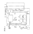
- the fuel cell system of the present embodiment includes a power generation unit 10 and a hot water storage tank 21.
- the power generation unit 10 includes a fuel cell module 11, a heat exchanger 12, an inverter device 13, a water tank 14 and a control apparatus 15.
- the fuel cell module 11 is constituted to include at least a fuel cell apparatus 43 as will be described later.
- the fuel cell module 11 is supplied with a reforming material, reforming water and cathode air.
- a reforming material supply pipe 11a which is for supply of the reforming material used for the reforming, is connected to a supply source Gs and the other end of the reforming material supply pipe 11 a is connected to the fuel cell module 11.
- a reforming material pump 11a1 is provided at the reforming material supply pipe 11a.
- one end of a water supply pipe 11b which is for supply of the reforming water, is connected to a water tank 14 and the other end of the water supply pipe 11b is connected to the fuel cell module 11.
- a reforming water pump 11b1 is provided at the water supply pipe 11b. Further, one end of a cathode air supply pipe 11c, which is for supply of the cathode air, is connected to a cathode air blower 11c1 and the other end of the cathode air supply pipe 11c is connected to the fuel cell module 11.
- the heat exchanger 12 is supplied with an exhaust combustion gas discharged from the fuel cell module 11 and is supplied with stored hot water from the hot water storage tank 21, and accordingly, heat exchange is performed between the exhaust combustion gas and the stored hot water at the heat exchanger 12.
- the hot water storage tank 21 stores therein the stored hot water
- a stored hot water circulation line 22 through which the stored hot water circulates (the stored hot water circulates in a direction of the arrows with the double lines in Fig. 1 ) is connected to the hot water storage tank 21.
- a stored hot water circulation pump 22a and the heat exchanger 12 are provided on the stored hot water circulation line 22 to be arranged from a lower end to an upper end in this order, respectively.
- An exhaust pipe 11d from the fuel cell module 11 is connected, in a penetrating manner, to the heat exchanger 12.
- a condensed water supply pipe 12a which is connected to the water tank 14, is connected to the heat exchanger 12.
- the exhaust combustion gas from the fuel cell module 11 is introduced via the exhaust pipe 11d into the heat exchanger 12, where the heat exchange between the exhaust combustion gas and the stored hot water is performed, and the exhaust combustion gas is condensed and cooled down at the heat exchanger 12. After the condensation, the exhaust combustion gas is discharged to an outside via the exhaust pipe 11d.
- the condensed water is supplied to the water tank 14 via the condensed water supply pipe 12a.
- the water tank 14 is configured to purify the condensed water by means of ion-exchange resin.
- the heat exchanger 12, the hot water storage tank 21 and the stored hot water circulation line 22, which are described above, constitute an exhaust heat recovery system 20.
- the exhaust heat recovery system 20 recovers exhaust heat of the fuel cell module 11 in the stored hot water and stores the exhaust heat therein.
- direct current voltage outputted from the fuel cell apparatus 43 is inputted to the inverter device 13 and is converted into a predetermined alternating current voltage at the inverter device 13.
- the converted alternating current voltage is outputted to a power supply line 16b.
- the power supply line 16b is electrically connected to a system power supply 16a which is an alternating-current power supply, and to an external electric power load 16c (for example, an electric appliance).
- the alternating current voltage from the system power supply 16a is inputted into the inverter device 13 via the power supply line 16b and is converted into a predetermined direct current voltage at the inverter device 13.
- the converted direct current voltage is outputted to auxiliary apparatuses (for example, the pumps and a blower) and/or to the control apparatus 15.
- the control apparatus 15 drives the auxiliary apparatuses and thus controls driving or operation of the fuel cell system.
- the fuel cell module 11 corresponds to a solid oxide fuel cell (SOFC) module. As illustrated in Figs. 2 and 3 , the fuel cell module 11 includes a power generation portion 40, an exterior portion 50 accommodating the power generation portion 40, a first flow passage 60 and a second flow passage 70.
- SOFC solid oxide fuel cell
- an upper side and a lower side in Fig. 2 correspond to an upper side and a lower side of the fuel cell module 11, respectively.
- a right side and a left side in Fig. 2 correspond to a rear side and a front side of the fuel cell module 11, respectively.
- a front side and a back side of the paper surface on which Fig. 2 is drawn correspond to a left side and a right side of the fuel cell module 11, respectively.
- arrows are illustrated to indicate the aforementioned directions.
- the power generation portion 40 includes an evaporating portion 41, a reforming portion 42, the fuel cell apparatus 43, a combusting space R corresponding to a combusting portion 44, and a heat insulating member 45.
- the evaporating portion 41 and the reforming portion 42 are arranged to be positioned at an upper side relative to the fuel cell apparatus 43.
- the combusting space R (the combusting portion 44) is arranged between the evaporating portion 41 and the reforming portion 42, and the fuel cell apparatus 43.
- the other end of the reforming material supply pipe 11a and the other end of the water supply pipe 11 b are connected to the evaporating portion 41.
- the evaporating portion 41 is heated by a combustion gas which will be described below.
- the evaporating portion 41 evaporates the reforming water supplied via the water supply pipe 11 b, and generates and derives water vapor (water vapor for reforming).
- the evaporating portion 41 preheats the reforming material which is supplied via the reforming material supply pipe 11 a. Then, the water vapor (the water vapor for reforming) generated through the evaporation of the reforming water and the preheated reforming material are mixed with each other by the evaporating portion 41, and then the mixture is provided to the reforming portion 42.
- the reforming material includes gaseous fuel for reforming, such as natural gas and liquefied petroleum gas (LPG), and liquid fuel for reforming, such as kerosene, gasoline and methanol.
- gaseous fuel for reforming such as natural gas and liquefied petroleum gas (LPG)
- liquid fuel for reforming such as kerosene, gasoline and methanol.
- the explanation is made on a case where the natural gas is used.
- the reforming portion 42 generates a reformed gas (which serves as an anode gas, and thus which will be hereinafter referred to as the anode gas) from the reforming material and the water vapor (the water vapor for reforming). Specifically, the reforming portion 42 is heated by the combustion gas, which will be described below, and thus the heat needed for a steam reforming reaction is supplied to the reforming portion 42. Then, at the reforming portion 42, the anode gas is generated and derived from the mixed gas (the reforming material, the water vapor for reforming) that is supplied from the evaporating portion 41.
- the anode gas which serves as an anode gas, and thus which will be hereinafter referred to as the anode gas
- the reforming portion 42 is heated by the combustion gas, which will be described below, and thus the heat needed for a steam reforming reaction is supplied to the reforming portion 42.
- the anode gas is generated and derived from the mixed gas (the reforming material, the water vapor for reform
- An inside of the reforming portion 42 is filled with catalyst (for example, ruthenium (Ru) based catalyst or nickel (Ni) based catalyst, and the reaction of the mixed gas is catalyzed and the mixed gas is reformed, and consequently, a hydrogen gas and a carbon monoxide gas are generated (the so-called steam reforming reaction).
- catalyst for example, ruthenium (Ru) based catalyst or nickel (Ni) based catalyst
- the reaction of the mixed gas is catalyzed and the mixed gas is reformed, and consequently, a hydrogen gas and a carbon monoxide gas are generated (the so-called steam reforming reaction).
- the carbon monoxide and the water vapor which are generated by the steam reforming reaction, react to each other and are converted to hydrogen gas and carbon dioxide, that is, a so-called carbon monoxide shift reaction occurs.
- the generated gasses (the anode gas) are provided to the fuel cell apparatus 43.
- the anode gas includes hydrogen, carbon monoxide, carbon dioxide, water vapor, unused natural gas (methane gas), and the reforming water (the water vapor) that was not used in the reforming.
- the steam reforming reaction is an endoergic reaction and the carbon monoxide shift reaction is an exoergic reaction.
- the fuel cell apparatus 43 includes a fuel cell 43a and a manifold 43b.
- the fuel cell 43a produces electric power from the anode gas and the cathode gas.
- the cathode gas corresponds to oxidant gas.
- the oxidant gas corresponds to air.
- the fuel cell 43a is constituted by plural cells stacked one another along a front/rear direction in Fig. 3 .
- the cell is constituted by a fuel electrode, an air electrode (an oxidant electrode) and electrolyte arranged between the fuel electrode and the air electrode.
- the fuel cell of the present embodiment is a solid oxide fuel cell (SOFC) and zirconium oxide, which is a type of solid oxide, is used as the electrolyte.
- SOFC solid oxide fuel cell
- zirconium oxide zirconium oxide
- fuel for example, hydrogen, carbon monoxide and methane gas are supplied to the fuel electrode of the fuel cell 43a.
- An operation temperature of the fuel cell 43a is approximately 400 °C to 1000 °C.
- the fuel not only the hydrogen but also natural gas and/or coal gas may be used as a direct fuel. In this case, the reforming portion 42 may be omitted.
- a fuel flow passage is provided at the fuel electrode-side of the cell.
- the anode gas which serves as the fuel, flows through the fuel flow passage.
- An air flow passage is provided at the air electrode-side of the cell. The air (the cathode air), which serves as cathode gas, flows through the air flow passage.
- the fuel cell 43a is arranged on the manifold 43b.
- the anode gas is supplied from the reforming portion 42 via a reformed gas supply pipe to the manifold 43b.
- a lower end (one end) of the fuel flow passage is connected to a fuel outlet port of the manifold 43b.
- the anode gas provided from the fuel outlet port is introduced from the lower end of the fuel flow passage, and then comes out from an upper end thereof.
- the cathode air is introduced from a lower end of the air flow passage, and then comes out from an upper end thereof.
- the power generation is performed with the anode gas supplied to the fuel electrode and the cathode gas supplied to the air electrode. That is, the reactions presented by a chemical formula 1 and a chemical formula 2, which are stated below, occurs at the fuel electrode.
- (Formula 1) H 2 + O 2- ⁇ H 2 O + 2e - (Formula 2) CO + O 2- ⁇ CO 2 + 2e - (Formula 3) 1/2O 2 + 2e - ⁇ O 2-
- the anode gas coming out from the fuel flow passage and the air flow passage which is the anode gas not used for the power generation (that is, an anode off-gas) is combusted in the combusting space R by the cathode gas which is not used for the power generation (that is, a cathode off-gas).
- the evaporating portion 41 and the reforming portion 42 are heated by the combustion gas (flame 44a). Further, the combustion gas heats an inside of the power generation portion 40 to the operation temperature.
- the combusting space R corresponds to the combusting portion 44 at which the anode off-gas from the fuel cell 43a and the cathode off-gas from the fuel cell 43a are combusted or burnt, and which heats the reforming portion 42 accordingly.
- the combusting portion 44 (the combusting space R) is for burning a combustible gas and the oxidant gas.
- the combustible gas is a gas that is combustible and, in the present embodiment, the combustible gas corresponds to the fuel for reforming, the anode off-gas, carbon monoxide and the like. That is, the combusting portion 44 is for combusting the anode off-gas coming out from the fuel cell 43a. Then, the combusting portion 44 combusts the anode off-gas and generates the exhaust combustion gas.
- the exhaust combustion gas is discharged to an outside of a second cylindrical member 52 which will be described later, that is, discharged to the atmosphere.
- the heat insulating member 45 thermally insulates the fuel cell 43a and an outside of the fuel cell 43a (that is, an outside of the power generation portion 40 or of the fuel cell module 11).
- the heat insulating member 45 is made from a heat insulating material having high heat insulating properties, for example, ceramics.
- the heat insulating member 45 includes a cross-sectional shape of a letter U opening upwardly (refer to Fig. 3 ).
- the evaporating portion 41, the reforming portion 42 and the fuel cell apparatus 43 are provided inside the heat insulating member 45.
- a bottom surface of the fuel cell apparatus 43 is in contact with a lower surface of the inside of the heat insulating member 45.
- a part of an outer wall surface of the power generation portion 40 is formed by, that is, defined by an outer wall surface 45a of the heat insulating member 45.
- the exterior portion 50 includes a first cylindrical member 51, the second cylindrical member 52, a first cover member 53, a second cover member 54, a first communication pipe member 55 (which serves as a communication pipe member) and a second communication pipe member 56.
- Each of the first cylindrical member 51, the second cylindrical member 52, the first cover member 53, the second cover member 54, the first communication pipe member 55 and the second communication pipe member 56 is made of metal, for example, carbon steel or steel alloy.
- Each of the first cylindrical member 51, the second cylindrical member 52, the first cover member 53, the second cover member 54, the first communication pipe member 55 and the second communication pipe member 56 is formed by means of, for example, press working and/or welding.
- the first cylindrical member 51 is formed in a cylindrical shape and is arranged to surround the power generation portion 40. Specifically, as illustrated mainly in Fig. 4 , the first cylindrical member 51 includes a first peripheral side wall 51a formed to have a substantially quadrate-shaped cross section. Further, the first cylindrical member 51 includes first and second opening portions 51b which are respectively provided at both ends of the first cylindrical member 51. An inner surface of the first peripheral side wall 51a faces the outer wall surface of the power generation portion 40 while a first space portion S1 is provided between the inner surface of the first peripheral side wall 51 a and the outer wall surface of the power generation portion 40 (refer to Fig. 3 ). The first cylindrical member 51 is welded at a welded portion 51c.
- the welded portion 51c is provided over a right-side wall of the first peripheral side wall 51a in the front/rear direction.
- the first cylindrical member 51 includes an elongated hole 51d, a first through hole 51e (which serves as a first through hole), flange portions 51f and plural protruding portions 51g.
- the elongated hole 51d is formed to penetrate an upper wall of the first peripheral side wall 51a and to be elongated in the front/rear direction.
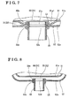
- the first through hole 51e is formed to penetrate a lower wall of the first peripheral side wall 51a. Specifically, the first through hole 51e penetrates a protruding end portion of a protruding portion 51a1. As illustrated in Figs. 3 and 7 , the protruding portion 51a1 is formed at the lower wall of the first peripheral side wall 51 a so as to protrude downwardly.
- the flange portion 51f is provided at a peripheral edge of each of the first and second opening portions 51 b of the first cylindrical member 51 over an entire circumference of each of the first and second opening portions 51b.
- the plural protruding portions 51g are provided at the right-side wall, a left-side wall and the lower wall of the first peripheral side wall 51a while a predetermined distance is provided between the neighboring protruding portions 51g.
- a protruding end surface of each of the protruding portions 51g is in contact with the outer wall surface 45a of the heat insulating member 45. Accordingly, the first space portion S1 is provided between the outer wall surface 45a and the inner surface of the first peripheral side wall 51a.
- the exterior portion 50 includes a gas introduction member 57.
- the gas introduction member 57 is formed in a cylindrical shape and is arranged at an upper wall of the first cylindrical member 51 so as to hang down from the upper wall or so as to be extended downwardly from the upper wall.
- the gas introduction member 57 includes a cylindrical portion 57a, an inlet port 57b and an outlet port 57c.
- An upper end portion of the cylindrical portion 57a is air-tightly connected to the elongated hole 51d.
- the cylindrical portion 57a is extended downwardly from the elongated hole 51d to a lower portion of the fuel cell 43a.
- the inlet port 57b is in fluid communication with a space portion (a second space portion S2) formed between an outer surface of the first peripheral side wall 51a of the first cylindrical member 51 and an inner surface of a second peripheral side wall 52a of the second cylindrical member 52.
- the outlet port 57c is formed at a lower end portion of the cylindrical portion 57a to open towards the lower portion of the fuel cell 43a.
- the second cylindrical member 52 is formed in a cylindrical shape and is arranged to surround the first cylindrical member 51.
- the second cylindrical member 52 includes the second peripheral side wall 52a formed to have a substantially quadrate-shaped cross section.
- the second cylindrical member 52 includes first and second opening portions 52b which are respectively provided at both ends of the second cylindrical member 52.
- the inner surface of the second peripheral side wall 52a faces the outer surface of the first peripheral side wall 51a of the first cylindrical member 51 while the second space portion S2 is provided between the inner surface of the second peripheral side wall 52a and the outer surface of the first peripheral side wall 51a (refer to Fig. 3 ).
- a length of the second peripheral side wall 52a of the second cylindrical member 52 in the front/rear direction is specified to be longer than a length of the first peripheral side wall 51 a of the first cylindrical member 51 in the front/rear direction.
- the second cylindrical member 52 is welded at a welded portion 52c.
- the welded portion 52c is provided over a right-side wall of the second peripheral side wall 52a in the front/rear direction.
- the second cylindrical member 52 includes a through bore 52d, a second through hole 52e (which serves as a second through hole), and flange portions 52f.
- Each of the through bore 52d and the second through hole 52e is formed to penetrate a lower wall of the second peripheral side wall 52a.
- a peripheral portion of the first through hole 51e of the first cylindrical member 51 is in contact with a peripheral edge portion of the second through hole 52e.
- the flange portion 52f is provided at a peripheral edge of each of the first and second opening portions 52b of the second cylindrical member 52 over an entire circumference of each of the first and second opening portions 52b.
- the first cylindrical member 51 and the second cylindrical member 52 are joined to each other in a state where end portions of the first cylindrical member 51 and end portions of the second cylindrical member 52 are joined to each other, respectively, by means of clinching or crimping. That is, the first cylindrical member 51 and the second cylindrical member 52 are joined to each other at portions where the flange portions 51f of the first cylindrical member 51 and the second peripheral side wall 52a of the second cylindrical member 52 are in contact with each other.
- the second peripheral side wall 52a of the second cylindrical member 52 is bent along an entire periphery thereof so that the inner surface of the second peripheral side wall 52a is in close contact with both side surfaces of the flange portion 51f.
- a joint portion C1 which is at each of the end portions of the first cylindrical member 51 and second cylindrical member 52, includes airtightness against the gas. Because an end surface 51f1 of each flange portion 51f of the first cylindrical member 51 is in contact with the inner surface of the second peripheral side wall 52a, the second space portion S2 is formed between the outer surface of the first peripheral side wall 51 a of the first cylindrical member 51 and the inner surface of the second peripheral side wall 52a of the second cylindrical member 52.
- the first cover member 53 is formed to cover at least one of the first opening portion 51b of the first cylindrical member 51 (in the present embodiment, the opening portion which is arranged at a front side) and the first opening portion 52b of the second cylindrical member 52.
- the first cover member 53 is joined to the at least one of the first opening portion 51 b of the first cylindrical member 51 and the first opening portion 52b of the second cylindrical member 52 throughout an entire circumference of the at least one of the first opening portion 51b of the first cylindrical member 51 and the first opening portion 52b of the second cylindrical member 52.
- the first cover member 53 is joined to the at least one of the first opening portion 51b of the first cylindrical member 51 and the first opening portion 52b of the second cylindrical member 52 by clinching, that is, by means of clinch joining or clinch connection.
- the first cover member 53 is formed in a substantially quadrate plate shape to cover or close the first opening portion 52b, which is at the front side, of the second cylindrical member 52 (refer to Fig. 5 ).
- the first cover member 53 is clinched and joined to the first opening portion 52b, which is at the front side, of the second cylindrical member 52 throughout the entire circumference of the first opening portion 52b. Specifically, peripheral edge portions of the respective first cover member 53 and the flange portion 52f of the second cylindrical member 52 are folded or bent at least twice.
- a joint portion C2 at which the first cover member 53 and the second cylindrical member 52 are joined to each other includes the airtightness against the gas.
- the second cover member 54 is formed to cover at least one of the second opening portion 51b of the first cylindrical member 51 (in the present embodiment, the opening portion which is arranged at a rear side) and the second opening portion 52b of the second cylindrical member 52.
- the second cover member 54 is joined to the at least one of the second opening portion 51b of the first cylindrical member 51 and the second opening portion 52b of the second cylindrical member 52 over an entire circumference of the at least one of the second opening portion 51b of the first cylindrical member 51 and the second opening portion 52b of the second cylindrical member 52.
- the second cover member 54 is joined to the at least one of the second opening portion 51 b of the first cylindrical member 51 and the second opening portion 52b of the second cylindrical member 52 by clinching, that is, by means of clinch joining.
- the second cover member 54 is formed in a substantially quadrate plate shape to cover or close the second opening portion 52b of the second cylindrical member 52 (refer to Fig. 5 ).
- the second cover member 54 is clinched and joined to the second opening portion 52b, which is at the rear side, of the second cylindrical member 52 throughout the entire circumference thereof.
- peripheral edge portions of the respective second cover member 54 and the flange portion 52f of the second cylindrical member 52 are folded or bent at least twice. Accordingly, a joint portion, at which the second cover member 54 and the second cylindrical member 52 are joined to each other, includes the airtightness against the gas.
- the first communication pipe member 55 is formed in a tubular shape or a cylindrical shape and establishes a fluid communication between the first space portion S1 and the outside of the second cylindrical member 52 (the atmosphere).
- the first space portion S1 corresponds to the portion formed between the outer wall surface of the power generating portion 40 and the inner surface of the first peripheral side wall 51 a of the first cylindrical member 51.
- a first opening end portion (i.e., an opening end portion) of the first communication pipe member 55 is arranged to penetrate the first cylindrical member 51 and the second cylindrical member 52, and to be in fluid communication with the first flow passage 60.
- the peripheral edge portion of the first through hole 51e of the first cylindrical member 51 and the peripheral edge portion of the second through hole 52e of the second cylindrical member 52 are arranged to be overlapped with each other.
- the first communication pipe member 55 is joined to the first cylindrical member 51 and the second cylindrical member 52 in a state where the first opening end portion of the first communication pipe member 55 is clinched to the peripheral edge portion of the first through hole 51e and to the peripheral edge portion of the second through hole 52e, the peripheral edge portions are overlapped with each other.
- the first opening end portion of the first communication pipe member 55 is bent and folded so that a bent portion 55a having an annular configuration is formed at the first opening end portion of the first communication pipe member 55.
- the first communication pipe member 55 is inserted, from a second opening end portion of the first communication pipe member 55, into each of the first and second through holes 51e and 52e until the bent portion 55a comes in contact with an inner surface (that is, the surface facing towards the power generation portion 40) of the peripheral portion of the first through hole 51 e.
- a joint portion C3 at which the first opening end portion of the first communication pipe member 55, and the first cylindrical member 51 and the second cylindrical member 52 are joined to one another, includes the airtightness against the gas
- the second communication pipe member 56 is formed in a tubular shape and establishes a fluid communication between the second space portion S2 and the outside of the second cylindrical member 52 (the atmosphere).
- the second space portion S2 corresponds to the space portion formed between the outer surface of the first peripheral side wall 51 a of the first cylindrical member 51 and the inner surface of the second peripheral side wall 52a of the second cylindrical member 52 (the second space portion S2).
- a first opening end portion of the second communication pipe member 56 is arranged to penetrate the second cylindrical member 52, and to be in fluid communication with a second flow passage 70.
- the second communication pipe member 56 and the second cylindrical member 52 are joined to each other in a state where the first opening end portion of the second communication pipe member 56 and a peripheral portion of the through bore 52d of the second cylindrical member 52 are clinched to each other.
- the first opening end portion of the second communication pipe member 56 is bent and folded so that a bent portion 56a having an annular configuration is formed at the first opening end portion of the second communication pipe member 56.
- the second communication pipe member 56 is inserted, from a second opening end portion of the second communication pipe member 56, into the through bore 52d until the bent portion 56a comes in contact with an inner surface of the peripheral portion of the through bore 52d.
- a joint portion C4 at which the first opening end portion of the second communication pipe member 56, and the second cylindrical member 52 are joined to each other, includes the airtightness against the gas.
- the first flow passage 60 is formed between the outer wall surface of the power generation portion 40 and the inner surface of the first peripheral side wall 51 a of the first cylindrical member 51 (the first space portion S1).
- One of the anode gas, the cathode gas and the exhaust combustion gas flows through the first flow passage 60.
- the exhaust combustion gas flows through the first flow passage 60. That is, the first flow passage 60 corresponds to an exhaust combustion gas flow passage.
- the exhaust combustion gas is discharged from the combusting portion 44 to the outside of the second cylindrical member 52 (that is, to the atmosphere) via the first flow passage 60 and the first communication pipe member 55.
- the second flow passage 70 is formed between the outer surface of the first peripheral side wall 51a of the first cylindrical member 51 and the inner surface of the second peripheral side wall 52a of the second cylindrical member 52 (the second space portion S2). Another of the anode gas, the cathode gas and the exhaust combustion gas flows through the second flow passage 70.
- the cathode gas flows through the second flow passage 70. That is, the second flow passage 70 corresponds to the cathode gas flow passage.
- the other end of the cathode air supply pipe 11c is connected to the second opening end portion of the second communication pipe member 56 as illustrated in Fig. 2 .
- the cathode air is supplied by the cathode air blower 11c1 to the second communication pipe member 56 via the cathode air supply pipe 11c. Then, as shown with the dotted arrows in Fig. 3 , the cathode gas is supplied to the lower end of the air flow passage of the fuel cell 43a via the second flow passage 70 and the gas introduction member 57, which are in fluid communication with the second communication pipe member 56.
- the exhaust combustion gas flowing through the first flow passage 60 and the cathode gas flowing through the second flow passage 70 flow in opposite directions to each other (a countercurrent type). Accordingly, heat exchange is performed efficiently between the cathode gas and the exhaust combustion gas. That is, the cathode gas is preheated by the exhaust combustion gas efficiently.
- the fuel cell module 11 includes the power generation portion 40 including the fuel cell 43a generating the electric power from the anode gas and the cathode gas, and the combusting portion 44 combusting the anode off-gas and generating the exhaust combustion gas, the first cylindrical member 51, 151 formed in the cylindrical shape and arranged to surround the power generation portion 40, the first cylindrical member 51, 151 including the first peripheral side wall 51a including the inner surface facing the outer wall surface of the power generation portion 40 while the first space portion S1 is provided between the inner surface of the first peripheral side wall 51a and the outer wall surface of the power generation portion 40, the first cylindrical member 51, 151 including the first and second opening portions 51b provided at respective ends of the first cylindrical member 51,151, the second cylindrical member 52 formed in the cylindrical shape and arranged to surround the first cylindrical member 51, 151, the second cylindrical member 52 including the second peripheral side wall 52a including the inner surface facing the outer surface of the first peripheral side wall 51a of the first cylindrical member 51, 151 while the second space portion S
- the exterior portion 50 of the fuel cell module 11 is constituted by the first cylindrical member 51 and the second cylindrical member 52, each of which is formed in the cylindrical shape. Accordingly, compared to the known configuration where an exterior portion or an outer casing is constituted by a U-shaped member and a cover member closing an opening portion of the U-shaped member, the number of the parts and components constituting the fuel cell module 11 is reduced. Consequently, costs of the fuel cell module 11 may be reduced.
- joining of the U-shaped member and the cover member to each other includes plural joint portions.
- the first cover member 53 is joined to the at least one of the first opening portion 51 b of the first cylindrical member 51 and the first opening portion 52b of the second cylindrical member 52 over the entire circumference of the opening portion and therefore the number of the joint portions between the first cover member 53, and the at least one of the first cylindrical member 51 and the second cylindrical member 52 is reduced.
- the second cover member 54 is joined to the at least one of the second opening portion 51 b of the first cylindrical member 51 and the second opening portion 52b of the second cylindrical member 52 over the entire circumference of the opening portion, and therefore the number of the joint portions between the second cover member 54, and the at least one of the first cylindrical member 51 and the second cylindrical member 52 is reduced.
- first cover member 53 and the second cover member 54 are joined either to the first and second opening portions 51 b of the first cylindrical member 51 or to the first and second opening portions 52b of the first cylindrical member 52 along the entire circumference of the opening, and accordingly the members can be continuously joined to one another. Consequently, easiness in manufacturing the fuel cell module 11 is enhanced. As a result, the costs of the fuel cell module 11 are reduced while the easiness in manufacturing the fuel cell module 11 is enhanced.
- the first flow passage 60 corresponds to the exhaust combustion gas flow passage through which the exhaust combustion gas flows
- the second flow passage 70 corresponds to a cathode gas flow passage through which the cathode gas flows.
- the first flow passage 60 corresponds to the first space portion S1 formed between the plural protruding portions 51g provided at the first peripheral side wall 51a and the outer wall surface. Accordingly, the first space portion S1 is formed between the outer wall surface 45a and the inner surface of the first peripheral side wall 51a.
- first cylindrical member 51, 151 and the second cylindrical member 52 are joined to each other in a state where the end portions of the first cylindrical member 51, 151 and the end portions of the second cylindrical member 52 are clinched to each other, respectively, the joining of the first cover member 53, and the at least one of the first opening portion 51 b of the first cylindrical member 51, 151 and the first opening portion 52b of the second cylindrical member 52 corresponds to the clinch joining, and the joining of the second cover member 54, and the at least one of the second opening portion 51 b of the first cylindrical member 51, 151 and the second opening portion 52b of the second cylindrical member 52 corresponds to the clinch joining.
- the first cover member 53 and the second cover member 54 are joined either to the first and second opening portions 51b of the first cylindrical member 51 or to the first and second opening portions 52b of the second cylindrical member 52 over the entire circumference, and the members are joined to one another by clinching. Accordingly, the members are joined to one another easily while the airtightness of the joint portions is reliably ensured. As a result, the costs of the fuel cell module 11 are more reduced while the easiness in manufacturing the fuel cell module 11 is more enhanced.
- the fuel cell module 11 includes the first communication pipe member 55 formed in the cylindrical shape and connecting the first flow passage 60 and the outside of the second cylindrical member 52 to each other in such a manner that the first flow passage 60 and the outside of the second cylindrical member 52 are in the fluid communication with each other, the first peripheral side wall 51a of the first cylindrical member 51, 151 including the first through hole 51e and the second peripheral side wall 52a of the second cylindrical member 52 including the second through hole 52e, the peripheral edge portion of the first through hole 51e of the first cylindrical member 51, 151 and the peripheral edge portion of the second through hole 52e of the second cylindrical member 52 being overlapped with each other, and the first communication pipe member 55 being joined to the first cylindrical member 51, 151 and to the second cylindrical member 52 in a state where the first opening end portion of the first communication pipe member 55, and the peripheral edge portion of the first through hole 51e and the peripheral edge portion of the second through hole 52e are clinched to one another.
- the first communication pipe member 55, and the first and second cylindrical members 51 and 52 when joining the first communication pipe member 55, and the first and second cylindrical members 51 and 52 to one another, the first communication pipe member 55, and the first and second cylindrical members 51 and 52 are joined at a time. Accordingly, the members are joined to one another easily in a short period of time. As a result, the easiness in manufacturing the fuel cell module 11 is further enhanced while the costs of the fuel cell module 11 are reduced.
- the power generation portion 40 includes the heat insulating member 45 insulating the heat between the fuel cell 43a and the outside of the fuel cell 43a, and at least a part of the outer wall surface of the power generation portion 40 is formed by the outer wall surface 45a of the heat insulating member 45.
- the heat insulating member 45 conserves the heat of the fuel cell 43a
- the outer wall surface 45a of the heat insulating member 45 serves also as an inner wall surface of the first flow passage 60.
- the costs of the fuel cell module 11 are further reduced because the number of the parts and components of the fuel cell module 11 is reduced.
- each of the first cylindrical member 51 and the second cylindrical member 52 is formed in the cylindrical configuration, rigidity of the exterior portion 50 is relatively higher than a case where the exterior portion 50 is configured to include the U-shaped member as in the known configuration. Accordingly, wall thickness of the first peripheral side wall 51a and the second peripheral side wall 52a of the first cylindrical member 51 and the second cylindrical member 52 can be relatively reduced, and thus sizes of the first cylindrical member 51 and the second cylindrical member 52 are relatively reduced. Consequently size of the exterior portion 50 is relatively reduced. As a result, the size reduction and the cost reduction of the fuel cell module 11 are achieved.
- the second flow passage 70 is arranged to be closer to the fuel cell 43a.
- the cathode gas flowing through the second flow passage 70 is efficiently preheated by the heat caused by the operation of the fuel cell 43a, which operates at the relatively high temperature.
- the first cylindrical member 51 and the second cylindrical member 52 are formed to include the relatively small size, surface area of the first cylindrical member 51 and the second cylindrical member 52 is relatively small.
- the heat of the exhaust combustion gas and the cathode gas is prevented from being discharged from the fuel cell module 11 to the outside. Accordingly, the heat exchange is performed efficiently between the exhaust combustion gas and the cathode gas.
- the cathode gas is preheated by the exhaust combustion gas efficiently.
- the joint portions, at which the members are joined to each other by clinching, are joined only by means of clinching, that is, without use of, for example, sealing material. Accordingly, compared to a case where sealing material of which heat resistance is relatively low is used at the joint portions, the airtightness is reliably assured at each of the joint portions even in a case where the fuel cell 43a operates at the relatively high temperature.
- the aforementioned embodiment is an example of the fuel cell module disclosed here and the fuel cell module disclosed here is not limited to the aforementioned embodiment, and a modification may be applied.
- the first cylindrical member 51 and the gas introduction member 57 are formed to be the separate members in the aforementioned embodiment, however, the first cylindrical member 51 and the gas introduction member 57 may be formed integrally with each other.
- a first cylindrical member 151 may be used instead of the first cylindrical member 51 and the gas introduction member 57.
- the first cylindrical member 151 includes a left member 151h and a right member 151i.
- the left member 151h corresponds to a configuration of the left-side portion.
- the right member 151i corresponds to a configuration of the right-side portion.
- a vertical wall 151h1 including a cross-sectional shape of a letter U opening in the right direction is provided at an upper wall of the left member 151 h so as to hang or extend from the upper wall of the left member 151 h.
- a vertical wall 151i1 including a cross-sectional shape of a letter U opening in the left direction is provided at an upper wall of the right member 151i. so as to hang or extend from the upper wall of the right member 151i.
- the vertical walls 151h1 and 151i1 are extended from the upper walls of the left and right members 151 h and 151i, respectively, to the lower portion of the fuel cell 43a.
- Each of the vertical walls 151h1 and 151i1 may include a configuration of a substantially vertical wall.
- a right end surface of the left member 151h and a left end surface of the right member 151i are joined to each other, thereby forming the integrated piece.
- the integrated piece corresponds to the first cylindrical member 51 including the gas introduction member 57. Consequently, the number of parts and components which constitute the exterior portion 50 is reduced, and accordingly the costs of the fuel cell module 11 are even more reduced.
- each of the first cover member 53 and the second cover member 54 is joined only to the second cylindrical member 52.
- each of the first cover member 53 and the second cover member 54 may be joined only to the first cylindrical member 51.
- lengths of the first cylindrical member 51 and the second cylindrical member 52 may be specified so that the length of the first cylindrical member 51 in the front/rear direction is longer than the length of the second cylindrical member 52 in the front/rear direction.
- each of the first cover member 53 and the second cover member 54 may be joined to both the first cylindrical member 51 and the second cylindrical member 52.
- the lengths of the first cylindrical member 51 and the second cylindrical member 52 may be specified so that a peripheral edge portion of the flange portion 51f of the first cylindrical member 51 and the peripheral edge portion of the flange portion 52f of the second cylindrical member 52 are in contact with each other throughout the entire circumference thereof.
- Each of the first cover member 53 and the second cover member 54 may be joined to both the first cylindrical member 51 and the second cylindrical member 52.
- first cover member 53 and the second cover member 54 are in contact with the flange portions 51f of the first cylindrical member 51 and with the flange portions 52f of the second cylindrical member 52 throughout the entire circumference thereof so that the peripheral edge portions of the first cover member 53 and the second cover member 54 are in close contact with the flange portions 51f and with the flange portions 52f.
- the protruding portions 51 g are provided at the first peripheral side wall 51a of the first cylindrical member 51.
- plural protruding portions may be provided at the outer wall surface 45a of the heat insulating member 45 in a manner that each of the protruding portions protrudes toward the inner surface of the first peripheral side wall 51 a.
- the first flow passage 60 corresponds to the exhaust combustion gas flow passage and the second flow passage 70 corresponds to the cathode gas flow passage.
- the first flow passage 60 may correspond to the cathode gas flow passage and the second flow passage 70 may correspond to the exhaust combustion gas flow passage.
- the first flow passage 60 may correspond to an anode gas flow passage through which the anode gas flows and the second flow passage 70 may correspond to the exhaust combustion gas flow passage.
- the first flow passage 60 may correspond to the exhaust combustion gas flow passage and the second flow passage 70 may correspond the anode gas flow passage.
- the first flow passage 60 may correspond to the anode gas passage and the second flow passage 70 may correspond to the cathode bas flow passage.
- a fuel cell module (11) includes a power generation portion (40), a first cylindrical member (51, 151) arranged to surround the power generation portion and including a first peripheral side wall (51 a) and first and second opening portions (51 b), a second cylindrical member (52) arranged to surround the first cylindrical member and including a second peripheral side wall (52a) and first and second opening portions (52b), a first cover member (53) being joined to at least one of the first opening portion (51 b) of the first cylindrical member and the first opening portion (52b) of the second cylindrical member, a second cover member (54) being joined to at least one of the second opening portion (51 b) of the first cylindrical member and the second opening portion (52b) of the second cylindrical member, a first flow passage (60) and a second flow passage (70).
Landscapes
- Life Sciences & Earth Sciences (AREA)
- Engineering & Computer Science (AREA)
- Manufacturing & Machinery (AREA)
- Sustainable Development (AREA)
- Sustainable Energy (AREA)
- Chemical & Material Sciences (AREA)
- Chemical Kinetics & Catalysis (AREA)
- Electrochemistry (AREA)
- General Chemical & Material Sciences (AREA)
- Fuel Cell (AREA)
Applications Claiming Priority (1)
| Application Number | Priority Date | Filing Date | Title |
|---|---|---|---|
| JP2014012610A JP6398201B2 (ja) | 2014-01-27 | 2014-01-27 | 燃料電池モジュール |
Publications (2)
| Publication Number | Publication Date |
|---|---|
| EP2899787A1 true EP2899787A1 (de) | 2015-07-29 |
| EP2899787B1 EP2899787B1 (de) | 2017-07-26 |
Family
ID=52349951
Family Applications (1)
| Application Number | Title | Priority Date | Filing Date |
|---|---|---|---|
| EP14199970.6A Active EP2899787B1 (de) | 2014-01-27 | 2014-12-23 | Brennstoffzellenmodul |
Country Status (2)
| Country | Link |
|---|---|
| EP (1) | EP2899787B1 (de) |
| JP (1) | JP6398201B2 (de) |
Cited By (1)
| Publication number | Priority date | Publication date | Assignee | Title |
|---|---|---|---|---|
| EP3211705A1 (de) * | 2016-02-24 | 2017-08-30 | Aisin Seiki Kabushiki Kaisha | Brennstoffzellenmodul |
Families Citing this family (2)
| Publication number | Priority date | Publication date | Assignee | Title |
|---|---|---|---|---|
| JP2017045644A (ja) * | 2015-08-27 | 2017-03-02 | 京セラ株式会社 | モジュールおよびモジュール収容装置 |
| JP7322720B2 (ja) * | 2020-01-23 | 2023-08-08 | 株式会社アイシン | 燃料電池ケース |
Citations (3)
| Publication number | Priority date | Publication date | Assignee | Title |
|---|---|---|---|---|
| US20090176136A1 (en) * | 2008-01-04 | 2009-07-09 | Protonex Technology Corporation | Solid oxide fuel cell systems with hot zones and two-stage tail gas combustors |
| EP2608304A1 (de) * | 2011-12-20 | 2013-06-26 | Aisin Seiki Kabushiki Kaisha | Brennstoffzellenvorrichtung |
| EP2624352A1 (de) * | 2012-01-31 | 2013-08-07 | Aisin Seiki Kabushiki Kaisha | Brennstoffzellenvorrichtung |
Family Cites Families (6)
| Publication number | Priority date | Publication date | Assignee | Title |
|---|---|---|---|---|
| JPH0616282Y2 (ja) * | 1988-09-26 | 1994-04-27 | 三菱電機株式会社 | カートリッジ式油タンク |
| JP2005190739A (ja) * | 2003-12-24 | 2005-07-14 | Nissan Motor Co Ltd | 高温用絶縁容器及びその製造方法 |
| JP2006331928A (ja) * | 2005-05-27 | 2006-12-07 | Toshiba Corp | 燃料電池 |
| CA2659525A1 (en) * | 2008-03-25 | 2009-09-25 | Bdf Ip Holdings Ltd. | Fuel cell system with fuel cell stack receptacle |
| TW201308745A (zh) * | 2011-04-15 | 2013-02-16 | Jx Nippon Oil & Energy Corp | 燃料電池模組(一) |
| JP6050036B2 (ja) * | 2012-06-27 | 2016-12-21 | 京セラ株式会社 | 燃料電池装置 |
-
2014
- 2014-01-27 JP JP2014012610A patent/JP6398201B2/ja active Active
- 2014-12-23 EP EP14199970.6A patent/EP2899787B1/de active Active
Patent Citations (4)
| Publication number | Priority date | Publication date | Assignee | Title |
|---|---|---|---|---|
| US20090176136A1 (en) * | 2008-01-04 | 2009-07-09 | Protonex Technology Corporation | Solid oxide fuel cell systems with hot zones and two-stage tail gas combustors |
| EP2608304A1 (de) * | 2011-12-20 | 2013-06-26 | Aisin Seiki Kabushiki Kaisha | Brennstoffzellenvorrichtung |
| JP2013131329A (ja) | 2011-12-20 | 2013-07-04 | Aisin Seiki Co Ltd | 燃料電池装置 |
| EP2624352A1 (de) * | 2012-01-31 | 2013-08-07 | Aisin Seiki Kabushiki Kaisha | Brennstoffzellenvorrichtung |
Cited By (1)
| Publication number | Priority date | Publication date | Assignee | Title |
|---|---|---|---|---|
| EP3211705A1 (de) * | 2016-02-24 | 2017-08-30 | Aisin Seiki Kabushiki Kaisha | Brennstoffzellenmodul |
Also Published As
| Publication number | Publication date |
|---|---|
| JP2015141758A (ja) | 2015-08-03 |
| EP2899787B1 (de) | 2017-07-26 |
| JP6398201B2 (ja) | 2018-10-03 |
Similar Documents
| Publication | Publication Date | Title |
|---|---|---|
| CN106505227B (zh) | 燃料电池模块 | |
| CN111989808B (zh) | 燃料电池系统 | |
| JP6719070B2 (ja) | 高温動作形燃料電池および燃料電池システム。 | |
| US10320016B2 (en) | High-temperature fuel cell system | |
| US20160268615A1 (en) | Fuel cell module | |
| EP2899787B1 (de) | Brennstoffzellenmodul | |
| JP6219722B2 (ja) | 燃料電池発電装置および燃料電池システム | |
| US10128515B2 (en) | Fuel cell module | |
| JP2017033630A (ja) | 固体酸化物形燃料電池スタック、固体酸化物形燃料電池モジュールおよび固体酸化物形燃料電池システム | |
| US10790522B2 (en) | Fuel cell module | |
| JP2012221932A (ja) | 燃料電池モジュール | |
| JP2016072054A (ja) | 燃料電池モジュールおよび燃料電池システム | |
| EP3070775B1 (de) | Brennstoffzellensystem | |
| JP2016012526A (ja) | 燃料電池システム | |
| JP6699226B2 (ja) | 燃料電池モジュール | |
| JP6329025B2 (ja) | 燃料電池モジュールおよび燃料電池システム | |
| CN113161593B (zh) | 燃料电池壳体 | |
| JP2020145208A (ja) | 燃料電池モジュールおよび燃料電池システム。 | |
| EP3211705B1 (de) | Brennstoffzellenmodul | |
| JP6296541B2 (ja) | 固体酸化物形燃料電池スタック、固体酸化物形燃料電池モジュールおよび固体酸化物形燃料電池システム | |
| JP2021036487A (ja) | 燃料電池モジュール | |
| JP2019110008A (ja) | 燃料電池モジュールおよび燃料電池システム | |
| JP2024082906A (ja) | 燃料電池モジュール | |
| JP2016143604A (ja) | 燃料電池モジュール | |
| JP2008103298A (ja) | 燃料電池セル及びスタックの構造と発電方法 |
Legal Events
| Date | Code | Title | Description |
|---|---|---|---|
| PUAI | Public reference made under article 153(3) epc to a published international application that has entered the european phase |
Free format text: ORIGINAL CODE: 0009012 |
|
| 17P | Request for examination filed |
Effective date: 20141223 |
|
| AK | Designated contracting states |
Kind code of ref document: A1 Designated state(s): AL AT BE BG CH CY CZ DE DK EE ES FI FR GB GR HR HU IE IS IT LI LT LU LV MC MK MT NL NO PL PT RO RS SE SI SK SM TR |
|
| AX | Request for extension of the european patent |
Extension state: BA ME |
|
| 17P | Request for examination filed |
Effective date: 20150903 |
|
| RBV | Designated contracting states (corrected) |
Designated state(s): AL AT BE BG CH CY CZ DE DK EE ES FI FR GB GR HR HU IE IS IT LI LT LU LV MC MK MT NL NO PL PT RO RS SE SI SK SM TR |
|
| 17Q | First examination report despatched |
Effective date: 20160714 |
|
| REG | Reference to a national code |
Ref country code: DE Ref legal event code: R079 Ref document number: 602014012225 Country of ref document: DE Free format text: PREVIOUS MAIN CLASS: H01M0008020000 Ipc: H01M0008040070 |
|
| GRAP | Despatch of communication of intention to grant a patent |
Free format text: ORIGINAL CODE: EPIDOSNIGR1 |
|
| RIC1 | Information provided on ipc code assigned before grant |
Ipc: H01M 8/04007 20160101AFI20170315BHEP Ipc: H01M 8/2475 20160101ALI20170315BHEP Ipc: H01M 8/04014 20160101ALN20170315BHEP Ipc: H01M 8/0612 20160101ALI20170315BHEP Ipc: H01M 8/124 20160101ALN20170315BHEP |
|
| RIC1 | Information provided on ipc code assigned before grant |
Ipc: H01M 8/04007 20160101AFI20170320BHEP Ipc: H01M 8/2428 20160101ALN20170320BHEP Ipc: H01M 8/124 20160101ALN20170320BHEP Ipc: H01M 8/0612 20160101ALI20170320BHEP Ipc: H01M 8/2475 20160101ALI20170320BHEP Ipc: H01M 8/04014 20160101ALN20170320BHEP |
|
| INTG | Intention to grant announced |
Effective date: 20170404 |
|
| RIN1 | Information on inventor provided before grant (corrected) |
Inventor name: ENDO, SATOSHI |
|
| GRAS | Grant fee paid |
Free format text: ORIGINAL CODE: EPIDOSNIGR3 |
|
| GRAA | (expected) grant |
Free format text: ORIGINAL CODE: 0009210 |
|
| AK | Designated contracting states |
Kind code of ref document: B1 Designated state(s): AL AT BE BG CH CY CZ DE DK EE ES FI FR GB GR HR HU IE IS IT LI LT LU LV MC MK MT NL NO PL PT RO RS SE SI SK SM TR |
|
| REG | Reference to a national code |
Ref country code: GB Ref legal event code: FG4D |
|
| REG | Reference to a national code |
Ref country code: CH Ref legal event code: EP |
|
| REG | Reference to a national code |
Ref country code: AT Ref legal event code: REF Ref document number: 913085 Country of ref document: AT Kind code of ref document: T Effective date: 20170815 |
|
| REG | Reference to a national code |
Ref country code: IE Ref legal event code: FG4D |
|
| REG | Reference to a national code |
Ref country code: DE Ref legal event code: R096 Ref document number: 602014012225 Country of ref document: DE |
|
| REG | Reference to a national code |
Ref country code: NL Ref legal event code: MP Effective date: 20170726 |
|
| REG | Reference to a national code |
Ref country code: LT Ref legal event code: MG4D |
|
| REG | Reference to a national code |
Ref country code: AT Ref legal event code: MK05 Ref document number: 913085 Country of ref document: AT Kind code of ref document: T Effective date: 20170726 |
|
| PG25 | Lapsed in a contracting state [announced via postgrant information from national office to epo] |
Ref country code: NO Free format text: LAPSE BECAUSE OF FAILURE TO SUBMIT A TRANSLATION OF THE DESCRIPTION OR TO PAY THE FEE WITHIN THE PRESCRIBED TIME-LIMIT Effective date: 20171026 Ref country code: NL Free format text: LAPSE BECAUSE OF FAILURE TO SUBMIT A TRANSLATION OF THE DESCRIPTION OR TO PAY THE FEE WITHIN THE PRESCRIBED TIME-LIMIT Effective date: 20170726 Ref country code: AT Free format text: LAPSE BECAUSE OF FAILURE TO SUBMIT A TRANSLATION OF THE DESCRIPTION OR TO PAY THE FEE WITHIN THE PRESCRIBED TIME-LIMIT Effective date: 20170726 Ref country code: HR Free format text: LAPSE BECAUSE OF FAILURE TO SUBMIT A TRANSLATION OF THE DESCRIPTION OR TO PAY THE FEE WITHIN THE PRESCRIBED TIME-LIMIT Effective date: 20170726 Ref country code: FI Free format text: LAPSE BECAUSE OF FAILURE TO SUBMIT A TRANSLATION OF THE DESCRIPTION OR TO PAY THE FEE WITHIN THE PRESCRIBED TIME-LIMIT Effective date: 20170726 Ref country code: LT Free format text: LAPSE BECAUSE OF FAILURE TO SUBMIT A TRANSLATION OF THE DESCRIPTION OR TO PAY THE FEE WITHIN THE PRESCRIBED TIME-LIMIT Effective date: 20170726 Ref country code: SE Free format text: LAPSE BECAUSE OF FAILURE TO SUBMIT A TRANSLATION OF THE DESCRIPTION OR TO PAY THE FEE WITHIN THE PRESCRIBED TIME-LIMIT Effective date: 20170726 |
|
| PG25 | Lapsed in a contracting state [announced via postgrant information from national office to epo] |
Ref country code: GR Free format text: LAPSE BECAUSE OF FAILURE TO SUBMIT A TRANSLATION OF THE DESCRIPTION OR TO PAY THE FEE WITHIN THE PRESCRIBED TIME-LIMIT Effective date: 20171027 Ref country code: IS Free format text: LAPSE BECAUSE OF FAILURE TO SUBMIT A TRANSLATION OF THE DESCRIPTION OR TO PAY THE FEE WITHIN THE PRESCRIBED TIME-LIMIT Effective date: 20171126 Ref country code: RS Free format text: LAPSE BECAUSE OF FAILURE TO SUBMIT A TRANSLATION OF THE DESCRIPTION OR TO PAY THE FEE WITHIN THE PRESCRIBED TIME-LIMIT Effective date: 20170726 Ref country code: LV Free format text: LAPSE BECAUSE OF FAILURE TO SUBMIT A TRANSLATION OF THE DESCRIPTION OR TO PAY THE FEE WITHIN THE PRESCRIBED TIME-LIMIT Effective date: 20170726 Ref country code: BG Free format text: LAPSE BECAUSE OF FAILURE TO SUBMIT A TRANSLATION OF THE DESCRIPTION OR TO PAY THE FEE WITHIN THE PRESCRIBED TIME-LIMIT Effective date: 20171026 Ref country code: PL Free format text: LAPSE BECAUSE OF FAILURE TO SUBMIT A TRANSLATION OF THE DESCRIPTION OR TO PAY THE FEE WITHIN THE PRESCRIBED TIME-LIMIT Effective date: 20170726 Ref country code: ES Free format text: LAPSE BECAUSE OF FAILURE TO SUBMIT A TRANSLATION OF THE DESCRIPTION OR TO PAY THE FEE WITHIN THE PRESCRIBED TIME-LIMIT Effective date: 20170726 |
|
| PG25 | Lapsed in a contracting state [announced via postgrant information from national office to epo] |
Ref country code: DK Free format text: LAPSE BECAUSE OF FAILURE TO SUBMIT A TRANSLATION OF THE DESCRIPTION OR TO PAY THE FEE WITHIN THE PRESCRIBED TIME-LIMIT Effective date: 20170726 Ref country code: RO Free format text: LAPSE BECAUSE OF FAILURE TO SUBMIT A TRANSLATION OF THE DESCRIPTION OR TO PAY THE FEE WITHIN THE PRESCRIBED TIME-LIMIT Effective date: 20170726 Ref country code: CZ Free format text: LAPSE BECAUSE OF FAILURE TO SUBMIT A TRANSLATION OF THE DESCRIPTION OR TO PAY THE FEE WITHIN THE PRESCRIBED TIME-LIMIT Effective date: 20170726 |
|
| REG | Reference to a national code |
Ref country code: DE Ref legal event code: R097 Ref document number: 602014012225 Country of ref document: DE |
|
| PG25 | Lapsed in a contracting state [announced via postgrant information from national office to epo] |
Ref country code: EE Free format text: LAPSE BECAUSE OF FAILURE TO SUBMIT A TRANSLATION OF THE DESCRIPTION OR TO PAY THE FEE WITHIN THE PRESCRIBED TIME-LIMIT Effective date: 20170726 Ref country code: SM Free format text: LAPSE BECAUSE OF FAILURE TO SUBMIT A TRANSLATION OF THE DESCRIPTION OR TO PAY THE FEE WITHIN THE PRESCRIBED TIME-LIMIT Effective date: 20170726 Ref country code: SK Free format text: LAPSE BECAUSE OF FAILURE TO SUBMIT A TRANSLATION OF THE DESCRIPTION OR TO PAY THE FEE WITHIN THE PRESCRIBED TIME-LIMIT Effective date: 20170726 Ref country code: IT Free format text: LAPSE BECAUSE OF FAILURE TO SUBMIT A TRANSLATION OF THE DESCRIPTION OR TO PAY THE FEE WITHIN THE PRESCRIBED TIME-LIMIT Effective date: 20170726 |
|
| PLBE | No opposition filed within time limit |
Free format text: ORIGINAL CODE: 0009261 |
|
| STAA | Information on the status of an ep patent application or granted ep patent |
Free format text: STATUS: NO OPPOSITION FILED WITHIN TIME LIMIT |
|
| 26N | No opposition filed |
Effective date: 20180430 |
|
| REG | Reference to a national code |
Ref country code: CH Ref legal event code: PL |
|
| PG25 | Lapsed in a contracting state [announced via postgrant information from national office to epo] |
Ref country code: SI Free format text: LAPSE BECAUSE OF FAILURE TO SUBMIT A TRANSLATION OF THE DESCRIPTION OR TO PAY THE FEE WITHIN THE PRESCRIBED TIME-LIMIT Effective date: 20170726 |
|
| REG | Reference to a national code |
Ref country code: IE Ref legal event code: MM4A |
|
| PG25 | Lapsed in a contracting state [announced via postgrant information from national office to epo] |
Ref country code: MT Free format text: LAPSE BECAUSE OF NON-PAYMENT OF DUE FEES Effective date: 20171223 Ref country code: LU Free format text: LAPSE BECAUSE OF NON-PAYMENT OF DUE FEES Effective date: 20171223 |
|
| REG | Reference to a national code |
Ref country code: FR Ref legal event code: ST Effective date: 20180831 |
|
| REG | Reference to a national code |
Ref country code: BE Ref legal event code: MM Effective date: 20171231 |
|
| PG25 | Lapsed in a contracting state [announced via postgrant information from national office to epo] |
Ref country code: FR Free format text: LAPSE BECAUSE OF NON-PAYMENT OF DUE FEES Effective date: 20180102 Ref country code: IE Free format text: LAPSE BECAUSE OF NON-PAYMENT OF DUE FEES Effective date: 20171223 |
|
| PG25 | Lapsed in a contracting state [announced via postgrant information from national office to epo] |
Ref country code: CH Free format text: LAPSE BECAUSE OF NON-PAYMENT OF DUE FEES Effective date: 20171231 Ref country code: LI Free format text: LAPSE BECAUSE OF NON-PAYMENT OF DUE FEES Effective date: 20171231 Ref country code: BE Free format text: LAPSE BECAUSE OF NON-PAYMENT OF DUE FEES Effective date: 20171231 |
|
| PG25 | Lapsed in a contracting state [announced via postgrant information from national office to epo] |
Ref country code: HU Free format text: LAPSE BECAUSE OF FAILURE TO SUBMIT A TRANSLATION OF THE DESCRIPTION OR TO PAY THE FEE WITHIN THE PRESCRIBED TIME-LIMIT; INVALID AB INITIO Effective date: 20141223 Ref country code: MC Free format text: LAPSE BECAUSE OF FAILURE TO SUBMIT A TRANSLATION OF THE DESCRIPTION OR TO PAY THE FEE WITHIN THE PRESCRIBED TIME-LIMIT Effective date: 20170726 |
|
| GBPC | Gb: european patent ceased through non-payment of renewal fee |
Effective date: 20181223 |
|
| PG25 | Lapsed in a contracting state [announced via postgrant information from national office to epo] |
Ref country code: CY Free format text: LAPSE BECAUSE OF FAILURE TO SUBMIT A TRANSLATION OF THE DESCRIPTION OR TO PAY THE FEE WITHIN THE PRESCRIBED TIME-LIMIT Effective date: 20170726 |
|
| PG25 | Lapsed in a contracting state [announced via postgrant information from national office to epo] |
Ref country code: MK Free format text: LAPSE BECAUSE OF FAILURE TO SUBMIT A TRANSLATION OF THE DESCRIPTION OR TO PAY THE FEE WITHIN THE PRESCRIBED TIME-LIMIT Effective date: 20170726 |
|
| PG25 | Lapsed in a contracting state [announced via postgrant information from national office to epo] |
Ref country code: GB Free format text: LAPSE BECAUSE OF NON-PAYMENT OF DUE FEES Effective date: 20181223 |
|
| PG25 | Lapsed in a contracting state [announced via postgrant information from national office to epo] |
Ref country code: TR Free format text: LAPSE BECAUSE OF FAILURE TO SUBMIT A TRANSLATION OF THE DESCRIPTION OR TO PAY THE FEE WITHIN THE PRESCRIBED TIME-LIMIT Effective date: 20170726 |
|
| PG25 | Lapsed in a contracting state [announced via postgrant information from national office to epo] |
Ref country code: PT Free format text: LAPSE BECAUSE OF FAILURE TO SUBMIT A TRANSLATION OF THE DESCRIPTION OR TO PAY THE FEE WITHIN THE PRESCRIBED TIME-LIMIT Effective date: 20170726 |
|
| PG25 | Lapsed in a contracting state [announced via postgrant information from national office to epo] |
Ref country code: AL Free format text: LAPSE BECAUSE OF FAILURE TO SUBMIT A TRANSLATION OF THE DESCRIPTION OR TO PAY THE FEE WITHIN THE PRESCRIBED TIME-LIMIT Effective date: 20170726 |
|
| PGFP | Annual fee paid to national office [announced via postgrant information from national office to epo] |
Ref country code: DE Payment date: 20251028 Year of fee payment: 12 |