EP2899902A1 - Signalübertragungsverfahren und -vorrichtung - Google Patents
Signalübertragungsverfahren und -vorrichtung Download PDFInfo
- Publication number
- EP2899902A1 EP2899902A1 EP13793457.6A EP13793457A EP2899902A1 EP 2899902 A1 EP2899902 A1 EP 2899902A1 EP 13793457 A EP13793457 A EP 13793457A EP 2899902 A1 EP2899902 A1 EP 2899902A1
- Authority
- EP
- European Patent Office
- Prior art keywords
- signal
- power line
- sending
- transmission
- visible light
- Prior art date
- Legal status (The legal status is an assumption and is not a legal conclusion. Google has not performed a legal analysis and makes no representation as to the accuracy of the status listed.)
- Withdrawn
Links
- 238000000034 method Methods 0.000 title claims abstract description 53
- 230000008054 signal transmission Effects 0.000 title claims abstract description 23
- 230000005540 biological transmission Effects 0.000 claims abstract description 50
- 230000008878 coupling Effects 0.000 claims description 22
- 238000010168 coupling process Methods 0.000 claims description 22
- 238000005859 coupling reaction Methods 0.000 claims description 22
- 238000012545 processing Methods 0.000 claims description 16
- 238000001914 filtration Methods 0.000 claims description 4
- 238000004891 communication Methods 0.000 abstract description 88
- 238000005516 engineering process Methods 0.000 abstract description 13
- 230000010354 integration Effects 0.000 abstract description 6
- 230000008901 benefit Effects 0.000 abstract description 5
- 238000010276 construction Methods 0.000 abstract description 4
- 238000006243 chemical reaction Methods 0.000 description 10
- 238000010586 diagram Methods 0.000 description 10
- 238000003860 storage Methods 0.000 description 5
- 230000010365 information processing Effects 0.000 description 4
- 230000008569 process Effects 0.000 description 4
- 230000006855 networking Effects 0.000 description 3
- 230000006872 improvement Effects 0.000 description 2
- 238000012544 monitoring process Methods 0.000 description 2
- XLYOFNOQVPJJNP-UHFFFAOYSA-N water Substances O XLYOFNOQVPJJNP-UHFFFAOYSA-N 0.000 description 2
- 230000009471 action Effects 0.000 description 1
- 238000011161 development Methods 0.000 description 1
- 230000000694 effects Effects 0.000 description 1
- 230000014759 maintenance of location Effects 0.000 description 1
- 238000004377 microelectronic Methods 0.000 description 1
- 230000003287 optical effect Effects 0.000 description 1
- 238000011160 research Methods 0.000 description 1
- 239000007787 solid Substances 0.000 description 1
- 238000006467 substitution reaction Methods 0.000 description 1
Images

Classifications
-
- H—ELECTRICITY
- H04—ELECTRIC COMMUNICATION TECHNIQUE
- H04B—TRANSMISSION
- H04B10/00—Transmission systems employing electromagnetic waves other than radio-waves, e.g. infrared, visible or ultraviolet light, or employing corpuscular radiation, e.g. quantum communication
- H04B10/11—Arrangements specific to free-space transmission, i.e. transmission through air or vacuum
- H04B10/114—Indoor or close-range type systems
- H04B10/116—Visible light communication
-
- H—ELECTRICITY
- H04—ELECTRIC COMMUNICATION TECHNIQUE
- H04B—TRANSMISSION
- H04B10/00—Transmission systems employing electromagnetic waves other than radio-waves, e.g. infrared, visible or ultraviolet light, or employing corpuscular radiation, e.g. quantum communication
- H04B10/50—Transmitters
- H04B10/501—Structural aspects
- H04B10/502—LED transmitters
-
- H—ELECTRICITY
- H04—ELECTRIC COMMUNICATION TECHNIQUE
- H04B—TRANSMISSION
- H04B3/00—Line transmission systems
- H04B3/54—Systems for transmission via power distribution lines
-
- H—ELECTRICITY
- H04—ELECTRIC COMMUNICATION TECHNIQUE
- H04B—TRANSMISSION
- H04B2203/00—Indexing scheme relating to line transmission systems
- H04B2203/54—Aspects of powerline communications not already covered by H04B3/54 and its subgroups
- H04B2203/5429—Applications for powerline communications
- H04B2203/5441—Wireless systems or telephone
-
- H—ELECTRICITY
- H04—ELECTRIC COMMUNICATION TECHNIQUE
- H04B—TRANSMISSION
- H04B2203/00—Indexing scheme relating to line transmission systems
- H04B2203/54—Aspects of powerline communications not already covered by H04B3/54 and its subgroups
- H04B2203/5462—Systems for power line communications
- H04B2203/5483—Systems for power line communications using coupling circuits
Definitions
- the present invention relates to the field of communications, in particular to a signal transmission method and apparatus.
- High-speed power line communication is a communication mode which takes a power line as a communication medium.
- the power line is never an ideal communication medium, but with the continuous improvement of technology, especially the development of modulation technique and microelectronic technique, the practicability of power line communication (PLC) has become possible.
- PLC power line communication
- the earliest practical technique of high-speed power line communication is a communication system called "pulse control".
- the system provides one-way communication with an extremely low speed, with a transmitter power being several kilowatts and is mainly used for street lamps and load control. Since 1950, people have started to study the high frequency characteristics (5 kHz ⁇ 500 kHz) of a power line (mainly high-voltage) channel, and have developed power system dispatching communication and power line carrier based on the high frequency characteristics.
- Updated power line communication system can realize higher data transmission speed over channels with different band widths of the same power line via techniques such as orthogonal frequency division multiplexing (OFDM).
- OFDM orthogonal frequency division multiplexing
- the transmission capability is 10 kbit/s when ordinary daylight lamp is used.
- the transmission capability can reach more than 500 Mbit/s when a light emitting diode (LED for short) is used.
- the transmission distance can reach 1-2 kilometre.
- the most distinctive feature of the VLC is that the VLC can be combined with the technique of solid state lighting, and data transmission with visible light as a medium can be realized with a lighting device.
- Many research institutions around the world are now dedicated in realizing higher communication speed of visible light communication.
- LED lighting technique based visible light communication in combination with high-speed power line carrier communication technique can conveniently and rapidly construct a high-speed communication network and take the advantage of visible light communication and power line communication technique, by using visible light communication as a wireless access mode and using power line carrier communication as a signal return mode.
- visible light communication as a wireless access mode
- power line carrier communication as a signal return mode.
- how to integrate visible light communication as a wireless access mode with power line communication technique is not mentioned in relevant technique.
- a signal transmission method and device are provided in the embodiments of the present invention, so as to solve the problem of how to integrate visible light communication as a wireless access mode with power line communication technique is not mentioned in relevant technique.
- a signal transmission method includes: a terminal device obtaining a signal to be sent; and the terminal device sending the signal through a visible light medium, wherein after being demodulated, the signal sent through the visible light medium is carried on a power line for transmission.
- sending the signal, by the terminal device, through a visible light medium includes: sending, by the terminal device, the signal via an LED light source.
- sending the signal, by the terminal device, through the LED light source includes: sending, by the terminal device, the signal via the LED light source on a camera.
- the method further includes: receiving the signal via a light receiving device, and demodulating the signal; and carrying the demodulated signal on a power line carrier for transmission via a coupling transmission device.
- demodulating the signal includes: filtering the signal received by the light receiving device, demodulating the filtered signal, decoding the demodulated signal and sending the decoded signal to a first processor, wherein the first processor is configured to convert the signal from a digital signal to an analogue signal.
- carrying the demodulated signal on the power line carrier for transmission via the coupling transmission device includes: processing the signal via a first analogue front end, and then carrying the demodulated signal on the power line carrier for transmission via the coupling transmission device, wherein the first analogue front end includes a filter and an amplifier.
- the method further includes: sending the signal to an Internet via an access gateway.
- sending the signal to the Internet via the access gateway includes: sending the signal which is carried on the power line carrier to a second processor via a second analogue front end, and storing the signal in the second processor and sending the signal to the Internet via the access gateway, wherein the second processor is configured to convert the signal from an analogue signal to a digital signal, and the second analogue front end includes a filter and an amplifier.
- sending the signal to the Internet via the access gateway includes at least one of the following modes: a wired mode and a wireless mode.
- the terminal device includes at least one of the following: a cellphone, a tablet computer, a notebook computer, and a fixed terminal with a camera.
- a signal transmission apparatus including: an acquisition component, configured to acquire a signal to be sent; and a sending component, configured to send the signal through a visible light medium, wherein after being demodulated, the signal sent through the visible light medium is carried on a power line for transmission.
- the sending component includes: a sending unit, configured to send the signal through a light-emitting diode (LED) light source on a camera.
- a sending unit configured to send the signal through a light-emitting diode (LED) light source on a camera.
- LED light-emitting diode
- a signal transmission system including the signal transmission apparatus mentioned above, further including: a processing component, configured to receive the signal via a light receiving device, and demodulate the signal; and a carrying component, configured to carry the demodulated signal on a power line carrier for transmission via a coupling transmission device.
- a terminal device acquires a signal to be sent; and the terminal device sends the signal through a visible light medium, wherein after being demodulated, the signal sent through the visible light medium is carried on a power line for transmission.
- FIG. 1 is a flowchart of a signal transmission method according to an embodiment of the present invention. As shown in Fig. 1 , the method includes steps S102 and S104.
- step S102 a terminal device acquires a signal to be sent.
- step S104 the terminal device sends the signal through a visible light medium, wherein after being demodulated, the signal sent through the visible light medium is carried on a power line for transmission.
- the terminal device sends a signal to be sent through a visible light medium, and after being demodulated, the signal is carried on a power line for transmission, so that integration of the power line communication technique with visible light communication as a wireless access mode is realized.
- the problem in related technologies regarding the integration of the visible light communication as a wireless access manner with the power line communication technology is solved, the construction of the communication network can be more convenient and faster, and the advantages of the visible light communication and the power line communication technology are fully utilized.
- the terminal device may send the signal to be sent via an LED light source.
- the LED light source has a stronger transmission capability and a farther transmission distance, thus having a better communication effect.
- the signal may be sent via an LED light source (for example, a flashlight) on a camera of the terminal device. Since all the current terminal devices have a camera thereon, and the camera often has an LED flashlight thereon, this method is easy to implement and has good practicability.
- an LED light source for example, a flashlight
- a light receiving device coupled to the power line may also receive a signal and demodulate the signal; and then the demodulated signal is carried on a power line carrier via a coupling transmitting device for transmission.
- the method for demodulating the signal may be implemented in the following manner: the signal received by the light receiving device is filtered and then demodulated, and the demodulated signal is decoded and then sent to a first processor, wherein the first processor is configured to convert the signal from a digital signal to a analogue signal.
- carrying the demodulated signal on the power line carrier via a coupling transmission device may be implemented in the following manner: the demodulated signal is processed via a first analogue front end, and then the demodulated signal is carried on a power line carrier for transmission via a coupling transmission device, wherein the first analogue front end includes a filter and an amplifier.
- the signal may be sent to an Internet via an access gateway.
- the signal which is carried on the power line carrier may be sent to a second processor via a second analogue front end, and the signal is stored in the second processor and sent to the Internet via the access gateway, wherein the second processor is configured to convert the signal from an analogue signal to a digital signal, and the second analogue front end includes a filter and an amplifier.
- sending the signal to an Internet via an access gateway may be implemented via a wired mode and/or a wireless mode.
- the above-mentioned terminal device may be a cellphone, a tablet computer, a notebook computer, a fixed terminal with a camera and the like.
- a signal transmission apparatus located in the terminal device, is also provided in this embodiment.
- the apparatus is used for realizing the above-mentioned embodiments and example implementation, which is already explained and will not be described any more.
- the term "component" can realize the combination of software and/or hardware with a predetermined function.
- the apparatus described in the embodiments below is preferably implemented with software, implementation with hardware, or a combination of software and hardware can also be conceived.
- Fig. 2 shows a structural diagram of a signal transmission apparatus according to an embodiment of the present invention.
- the apparatus includes: an acquisition component 22 and a sending component 24, and the components are described in detail below.
- the acquisition component 22 is configured to acquire a signal to be sent.
- the sending component 24, coupled to the acquisition component 22, is configured to send through a visible light medium the signal acquired by the acquisition component 22, wherein after being demodulated, the signal sent through the visible light medium is carried on a power line for transmission.
- the terminal device sends a signal to be sent acquired by the acquisition component 22, through a visible light medium using the sending component 24, and after being demodulated, the signal is carried on a power line for transmission, so that the integration of the power line communication technique with visible light communication as a wireless access mode is realized.
- the problem in related technologies regarding the integration of the visible light communication as a wireless access manner with the power line communication technology is solved, the construction of the communication network can be more convenient and faster, and the advantages of the visible light communication and the power line communication technology are fully utilized.
- the sending component 24 may include: a sending unit, configured to send the signal through a light-emitting diode (LED) light source on a camera.
- a sending unit configured to send the signal through a light-emitting diode (LED) light source on a camera.
- LED light-emitting diode
- FIG. 3 shows a structural diagram of a signal transmission system according to an embodiment of the present invention.
- the system includes a signal transmission apparatus 20 as shown in Fig. 2 , and further includes: a processing component 32, coupled to the sending component 24, configured to receive the signal via a light receiving device, and demodulate the signal; and a carrying component 34, coupled to the processing component 32, configured to carry the demodulated signal on a power line carrier for transmission via a coupling transmission device.
- an architecture which integrates power line communication and visible light communication is provided.
- the architecture combines the power line carrier technique and visible light communication technique, realizes not only rapid and convenient networking but also the access to the Internet and the control of household appliance with widely distributed power lines and visible light as a medium.
- the visible light communication technique combined with the power line carrier communication technique, can provide a convenient, rapid and more price-advantage networking mode for a home network and an office network.
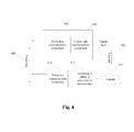
- Fig. 4 is a structural diagram showing an architecture containing both power line communication and visible light communication according to an example embodiment of the present invention.
- the processing components in the architecture include:
- the flow of the terminal sending a signal may be as follows.
- the terminal sends the signal to the visible light communication component 404 via a visible light medium; the visible light communication component 404 then demodulates the signal and sends the signal to the power line communication component 406 for processing; the signal is transmitted over the power line 408 and processed by the power line communication component 410, and is accessed to the Internet 414 via the ADSL or other Internet access device 412.
- the digital signal of the Internet 414 enters the power line communication component 410 via the ADSL or other access devices, and enters the power line for transmission via the power line conversion component.
- Fig. 5 is a schematic diagram of an information processing component which integrates power line carrier and visible light communication according to an example embodiment of the present invention. As shown in Fig. 5 , in an example embodiment, the following processing units are included.
- the information processing flow of the terminal may be as follows.
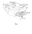
- FIG. 6 is a schematic diagram which combines power line communication and visible light communication according to embodiment 1 of the present invention. As shown in Fig. 6 , this architecture includes communication units as follows:
- a power line-visible light communication components 608 located in another room receives a visible light signal sent by a terminal device (for example, communication devices, such as cellphone, tablet computer, notebook computer) via an LED flashlight of the camera; the power line carrier signal is transmitted via the power line; the power line carrier signal is received by the power line-visible light component 606 and is connected to a wireless router via a wired or wireless interface of the power line-visible light component 606, and is accessed to the Internet 602 via the Internet gateway device 604 (for example, access devices such as asymmetric digital subscriber line (ADSL)).
- a terminal device for example, communication devices, such as cellphone, tablet computer, notebook computer
- the power line carrier signal is transmitted via the power line
- the power line carrier signal is received by the power line-visible light component 606 and is connected to a wireless router via a wired or wireless interface of the power line-visible light component 606, and is accessed to the Internet 602 via the Internet gateway device 604 (for example, access devices such as asymmetric digital subscriber line (
- a solution of controlling room appliances via power line-visible light communication is provided in this example embodiment.
- the household appliances including water heater, security and protection, lamplight, gas monitoring and the like, can be controlled via visible light communication.
- the steps of the solution are as follows:
- a storage medium is also provided.
- the software is stored on the storage medium, and the storage medium includes but is not limited to optical disks, floppy disks, hard disks, erasable storages, etc.
- each of the mentioned components or steps of the present invention can be realized by universal computing devices; the components or steps can be focused on single computing device, or distributed on the network formed by multiple computing devices; selectively, they can be realized by the program codes which can be executed by the computing device; thereby, the components or steps can be stored in the storage device and executed by the computing device; and under some circumstances, the shown or described steps can be executed in different orders, or can be independently manufactured as each integrated circuit component, or multiple components or steps thereof can be manufactured to be single integrated circuit component, thus to be realized. In this way, the present invention is not restricted to any particular hardware and software combination.
Landscapes
- Engineering & Computer Science (AREA)
- Computer Networks & Wireless Communication (AREA)
- Signal Processing (AREA)
- Physics & Mathematics (AREA)
- Electromagnetism (AREA)
- Power Engineering (AREA)
- Optical Communication System (AREA)
- Cable Transmission Systems, Equalization Of Radio And Reduction Of Echo (AREA)
Applications Claiming Priority (2)
| Application Number | Priority Date | Filing Date | Title |
|---|---|---|---|
| CN201210351822.5A CN103684529B (zh) | 2012-09-20 | 2012-09-20 | 信号传输方法及装置 |
| PCT/CN2013/078995 WO2013174307A1 (zh) | 2012-09-20 | 2013-07-08 | 信号传输方法及装置 |
Publications (2)
| Publication Number | Publication Date |
|---|---|
| EP2899902A1 true EP2899902A1 (de) | 2015-07-29 |
| EP2899902A4 EP2899902A4 (de) | 2016-06-22 |
Family
ID=49623162
Family Applications (1)
| Application Number | Title | Priority Date | Filing Date |
|---|---|---|---|
| EP13793457.6A Withdrawn EP2899902A4 (de) | 2012-09-20 | 2013-07-08 | Signalübertragungsverfahren und -vorrichtung |
Country Status (4)
| Country | Link |
|---|---|
| US (1) | US9461741B2 (de) |
| EP (1) | EP2899902A4 (de) |
| CN (1) | CN103684529B (de) |
| WO (1) | WO2013174307A1 (de) |
Cited By (1)
| Publication number | Priority date | Publication date | Assignee | Title |
|---|---|---|---|---|
| CN104980219A (zh) * | 2015-08-04 | 2015-10-14 | 北京奥普泰克科技有限责任公司 | 基于fsk调制和电力线载波的可见光通信系统 |
Families Citing this family (14)
| Publication number | Priority date | Publication date | Assignee | Title |
|---|---|---|---|---|
| CN104202438A (zh) * | 2014-07-30 | 2014-12-10 | 惠州Tcl移动通信有限公司 | 接口适配器、终端以及可见光通信系统 |
| CN104104440B (zh) * | 2014-08-07 | 2017-02-22 | 中国人民解放军信息工程大学 | 基于可见光通信的室内Femtocell组网通信系统 |
| CN107005276B (zh) * | 2015-03-13 | 2020-02-14 | 华为技术有限公司 | 一种网关侧电力线通信plc子系统、网关及耦合解耦器 |
| CN106327852A (zh) * | 2015-06-25 | 2017-01-11 | � 刘 | 一种基于闪光灯的手机控制的家电的系统和方法 |
| CN106066096A (zh) * | 2016-06-01 | 2016-11-02 | 苏州杰姆斯特机械有限公司 | 一种多网络远程光控的智能加热淋浴系统 |
| CN106788600A (zh) * | 2016-12-23 | 2017-05-31 | 福建省亿坤通信股份有限公司 | 一种基于载波通信芯片的可见光通信系统及方法 |
| CN106877928A (zh) * | 2016-12-23 | 2017-06-20 | 中国人民解放军信息工程大学 | 一种基于电力线通信的可见光通信系统及方法 |
| CN106850059A (zh) * | 2016-12-23 | 2017-06-13 | 国网福建省电力有限公司宁德供电公司 | 基于载波通信芯片的可见光通信射频上行通信系统及方法 |
| CN106992799A (zh) * | 2016-12-23 | 2017-07-28 | 中国人民解放军信息工程大学 | 一种具有wifi通信功能的可见光通信系统 |
| CN107547133B (zh) * | 2017-07-24 | 2020-04-10 | 上海师范大学 | 用于室内通信系统的基于ofdm技术的plc-vlc传输方法 |
| EP3729689A1 (de) * | 2017-09-08 | 2020-10-28 | Slux Sagl | System zur übertragung von daten mittels optischer strahlung mittels diffusion durch stromleitungen und zugehöriges verfahren |
| IT201700101065A1 (it) * | 2017-09-08 | 2019-03-08 | Slux Sagl | Sistema di trasmissione di dati mediante radiazione ottica mediante diffusione tramite onde convogliate e metodo associato |
| TWI737403B (zh) * | 2020-07-15 | 2021-08-21 | 南臺學校財團法人南臺科技大學 | 智慧型偵測裝置 |
| CN115882947B (zh) * | 2022-10-17 | 2025-08-22 | 厦门大学 | 一种基于电力线载波电路的可见光通信装置及其通信方法 |
Family Cites Families (13)
| Publication number | Priority date | Publication date | Assignee | Title |
|---|---|---|---|---|
| US20020040388A1 (en) * | 2000-08-15 | 2002-04-04 | Lockheed Martin Corporation | Method and apparatus for delivering services in a constrained environment |
| US7173935B2 (en) * | 2002-06-07 | 2007-02-06 | Current Grid, Llc | Last leg utility grid high-speed data communication network having virtual local area network functionality |
| WO2004038962A1 (ja) * | 2002-10-24 | 2004-05-06 | Nakagawa Laboratories, Inc. | 照明光通信装置 |
| JP2007274566A (ja) * | 2006-03-31 | 2007-10-18 | Nakagawa Kenkyusho:Kk | 照明光通信装置 |
| TWI349466B (en) * | 2007-10-12 | 2011-09-21 | Alpha Networks Inc | Power line adapter and method for controlling power line adepter to power saving mode |
| CN101232327B (zh) * | 2007-10-30 | 2011-05-18 | 华东理工大学 | 可见光空分多址多路通信系统 |
| CN101599781A (zh) * | 2008-06-06 | 2009-12-09 | 许浩坤 | Zigbee转电力线载波网关技术 |
| US20120001567A1 (en) * | 2009-09-30 | 2012-01-05 | Firefly Green Technologies, Inc. | Lighting Control System |
| US8494374B2 (en) * | 2010-06-14 | 2013-07-23 | Streamlight, Inc. | Portable light providing illumination and data |
| CN101945309A (zh) * | 2010-09-02 | 2011-01-12 | 李淑英 | 无源光网络结合电力线载波实现双向通讯的方法、系统和装置 |
| CN102081835A (zh) * | 2010-11-18 | 2011-06-01 | 广州广联数字家庭产业技术研究院 | 基于电力载波的远程抄表系统 |
| CN102624451A (zh) * | 2011-01-27 | 2012-08-01 | 郭丰亮 | 一种基于电力线载波的led可见光通信系统 |
| CN102624455A (zh) * | 2012-04-25 | 2012-08-01 | 武汉华炬光电有限公司 | 一种矿井使用的led可见光无线通信系统 |
-
2012
- 2012-09-20 CN CN201210351822.5A patent/CN103684529B/zh not_active Expired - Fee Related
-
2013
- 2013-07-08 EP EP13793457.6A patent/EP2899902A4/de not_active Withdrawn
- 2013-07-08 WO PCT/CN2013/078995 patent/WO2013174307A1/zh not_active Ceased
- 2013-07-08 US US14/429,533 patent/US9461741B2/en not_active Expired - Fee Related
Cited By (1)
| Publication number | Priority date | Publication date | Assignee | Title |
|---|---|---|---|---|
| CN104980219A (zh) * | 2015-08-04 | 2015-10-14 | 北京奥普泰克科技有限责任公司 | 基于fsk调制和电力线载波的可见光通信系统 |
Also Published As
| Publication number | Publication date |
|---|---|
| CN103684529B (zh) | 2018-01-23 |
| US9461741B2 (en) | 2016-10-04 |
| CN103684529A (zh) | 2014-03-26 |
| EP2899902A4 (de) | 2016-06-22 |
| WO2013174307A1 (zh) | 2013-11-28 |
| US20150304028A1 (en) | 2015-10-22 |
Similar Documents
| Publication | Publication Date | Title |
|---|---|---|
| US9461741B2 (en) | Signal transmission method and apparatus | |
| CN107911166B (zh) | 一种基于无线能量收割与非正交多址的可见光/射频混合协作通信方法 | |
| EP1990936A1 (de) | Drahtloses beleuchtungslichtübertragungssystem | |
| US9906297B2 (en) | Method and system for implementing visible-light communication, sending apparatus, and receiving apparatus | |
| WO2019100789A1 (zh) | 一种基于WiFi与LiFi混合型的通信系统 | |
| CN102811091A (zh) | 基于可见光通信的宽带接入装置及方法 | |
| CN205596120U (zh) | 一种高速led可见光通信系统及接收装置 | |
| CN204089821U (zh) | 一种可见光通信系统 | |
| CN204928832U (zh) | 一种基于智能终端的可见光数据传输系统 | |
| KR20160133838A (ko) | PCI Interface을 이용한 VLC 송, 수신기 | |
| Uysal | Visible light communications: from theory to industrial standardization | |
| CN108092718A (zh) | 基于大功率照明led灯的可见光接入网通信系统 | |
| CN103812560A (zh) | 基于可见光和无线电频的混合型通讯系统 | |
| CN106712849A (zh) | 基于光频梳的室内毫米波和可见光通信混合多接入方法 | |
| CN103974509A (zh) | Led智能控制方法和系统 | |
| WO2022236343A1 (en) | Two-mode smart lighting system for rf and lifi data transmission, and lifi light modulation method on three parallel data streams using both visible and infrared lights | |
| KR102010640B1 (ko) | 다중 사용자 전이중 가시광 통신 장치 | |
| CN103728934A (zh) | 一种智能家居系统 | |
| CN213365772U (zh) | 一种智能家电控制系统及用于遥控家电的照明灯具 | |
| CN111354179A (zh) | 一种基于电力载波通信与红外线遥控的智能家电控制系统 | |
| CN105207717A (zh) | 一种信息传输系统 | |
| CN202602631U (zh) | 基于电力线和可见光的通信系统 | |
| KR20110031264A (ko) | 가시광 통신 시스템에서 프랙셔널 자원 할당 장치 및 방법 | |
| KR101769619B1 (ko) | 가시광 통신 시스템에서 자원 할당을 위한 장치 및 방법 | |
| CN103312376B (zh) | 基于电力线和可见光的通信系统 |
Legal Events
| Date | Code | Title | Description |
|---|---|---|---|
| PUAI | Public reference made under article 153(3) epc to a published international application that has entered the european phase |
Free format text: ORIGINAL CODE: 0009012 |
|
| 17P | Request for examination filed |
Effective date: 20150325 |
|
| AK | Designated contracting states |
Kind code of ref document: A1 Designated state(s): AL AT BE BG CH CY CZ DE DK EE ES FI FR GB GR HR HU IE IS IT LI LT LU LV MC MK MT NL NO PL PT RO RS SE SI SK SM TR |
|
| AX | Request for extension of the european patent |
Extension state: BA ME |
|
| DAX | Request for extension of the european patent (deleted) | ||
| RA4 | Supplementary search report drawn up and despatched (corrected) |
Effective date: 20160520 |
|
| RIC1 | Information provided on ipc code assigned before grant |
Ipc: H04B 10/116 20130101AFI20160513BHEP Ipc: H04B 3/54 20060101ALI20160513BHEP |
|
| 17Q | First examination report despatched |
Effective date: 20171201 |
|
| STAA | Information on the status of an ep patent application or granted ep patent |
Free format text: STATUS: THE APPLICATION IS DEEMED TO BE WITHDRAWN |
|
| 18D | Application deemed to be withdrawn |
Effective date: 20200911 |