EP2900351B1 - Teilchentrennung und -konzentration mittels spiralförmiger inertialer filtration - Google Patents
Teilchentrennung und -konzentration mittels spiralförmiger inertialer filtration Download PDFInfo
- Publication number
- EP2900351B1 EP2900351B1 EP13841066.7A EP13841066A EP2900351B1 EP 2900351 B1 EP2900351 B1 EP 2900351B1 EP 13841066 A EP13841066 A EP 13841066A EP 2900351 B1 EP2900351 B1 EP 2900351B1
- Authority
- EP
- European Patent Office
- Prior art keywords
- fluid
- channel
- main channel
- main
- particle
- Prior art date
- Legal status (The legal status is an assumption and is not a legal conclusion. Google has not performed a legal analysis and makes no representation as to the accuracy of the status listed.)
- Active
Links
Images




Classifications
-
- G—PHYSICS
- G01—MEASURING; TESTING
- G01N—INVESTIGATING OR ANALYSING MATERIALS BY DETERMINING THEIR CHEMICAL OR PHYSICAL PROPERTIES
- G01N1/00—Sampling; Preparing specimens for investigation
- G01N1/28—Preparing specimens for investigation including physical details of (bio-)chemical methods covered elsewhere, e.g. G01N33/50, C12Q
- G01N1/34—Purifying; Cleaning
-
- G—PHYSICS
- G01—MEASURING; TESTING
- G01N—INVESTIGATING OR ANALYSING MATERIALS BY DETERMINING THEIR CHEMICAL OR PHYSICAL PROPERTIES
- G01N1/00—Sampling; Preparing specimens for investigation
- G01N1/28—Preparing specimens for investigation including physical details of (bio-)chemical methods covered elsewhere, e.g. G01N33/50, C12Q
- G01N1/40—Concentrating samples
- G01N1/4077—Concentrating samples by other techniques involving separation of suspended solids
-
- B—PERFORMING OPERATIONS; TRANSPORTING
- B01—PHYSICAL OR CHEMICAL PROCESSES OR APPARATUS IN GENERAL
- B01D—SEPARATION
- B01D21/00—Separation of suspended solid particles from liquids by sedimentation
- B01D21/0087—Settling tanks provided with means for ensuring a special flow pattern, e.g. even inflow or outflow
-
- B—PERFORMING OPERATIONS; TRANSPORTING
- B01—PHYSICAL OR CHEMICAL PROCESSES OR APPARATUS IN GENERAL
- B01D—SEPARATION
- B01D21/00—Separation of suspended solid particles from liquids by sedimentation
- B01D21/24—Feed or discharge mechanisms for settling tanks
- B01D21/2444—Discharge mechanisms for the classified liquid
-
- B—PERFORMING OPERATIONS; TRANSPORTING
- B01—PHYSICAL OR CHEMICAL PROCESSES OR APPARATUS IN GENERAL
- B01D—SEPARATION
- B01D21/00—Separation of suspended solid particles from liquids by sedimentation
- B01D21/26—Separation of sediment aided by centrifugal force or centripetal force
- B01D21/265—Separation of sediment aided by centrifugal force or centripetal force by using a vortex inducer or vortex guide, e.g. coil
-
- B—PERFORMING OPERATIONS; TRANSPORTING
- B01—PHYSICAL OR CHEMICAL PROCESSES OR APPARATUS IN GENERAL
- B01L—CHEMICAL OR PHYSICAL LABORATORY APPARATUS FOR GENERAL USE
- B01L3/00—Containers or dishes for laboratory use, e.g. laboratory glassware; Droppers
- B01L3/50—Containers for the purpose of retaining a material to be analysed, e.g. test tubes
- B01L3/502—Containers for the purpose of retaining a material to be analysed, e.g. test tubes with fluid transport, e.g. in multi-compartment structures
- B01L3/5027—Containers for the purpose of retaining a material to be analysed, e.g. test tubes with fluid transport, e.g. in multi-compartment structures by integrated microfluidic structures, i.e. dimensions of channels and chambers are such that surface tension forces are important, e.g. lab-on-a-chip
- B01L3/502753—Containers for the purpose of retaining a material to be analysed, e.g. test tubes with fluid transport, e.g. in multi-compartment structures by integrated microfluidic structures, i.e. dimensions of channels and chambers are such that surface tension forces are important, e.g. lab-on-a-chip characterised by bulk separation arrangements on lab-on-a-chip devices, e.g. for filtration or centrifugation
-
- B—PERFORMING OPERATIONS; TRANSPORTING
- B01—PHYSICAL OR CHEMICAL PROCESSES OR APPARATUS IN GENERAL
- B01L—CHEMICAL OR PHYSICAL LABORATORY APPARATUS FOR GENERAL USE
- B01L3/00—Containers or dishes for laboratory use, e.g. laboratory glassware; Droppers
- B01L3/50—Containers for the purpose of retaining a material to be analysed, e.g. test tubes
- B01L3/502—Containers for the purpose of retaining a material to be analysed, e.g. test tubes with fluid transport, e.g. in multi-compartment structures
- B01L3/5027—Containers for the purpose of retaining a material to be analysed, e.g. test tubes with fluid transport, e.g. in multi-compartment structures by integrated microfluidic structures, i.e. dimensions of channels and chambers are such that surface tension forces are important, e.g. lab-on-a-chip
- B01L3/502769—Containers for the purpose of retaining a material to be analysed, e.g. test tubes with fluid transport, e.g. in multi-compartment structures by integrated microfluidic structures, i.e. dimensions of channels and chambers are such that surface tension forces are important, e.g. lab-on-a-chip characterised by multiphase flow arrangements
- B01L3/502776—Containers for the purpose of retaining a material to be analysed, e.g. test tubes with fluid transport, e.g. in multi-compartment structures by integrated microfluidic structures, i.e. dimensions of channels and chambers are such that surface tension forces are important, e.g. lab-on-a-chip characterised by multiphase flow arrangements specially adapted for focusing or laminating flows
-
- B—PERFORMING OPERATIONS; TRANSPORTING
- B01—PHYSICAL OR CHEMICAL PROCESSES OR APPARATUS IN GENERAL
- B01L—CHEMICAL OR PHYSICAL LABORATORY APPARATUS FOR GENERAL USE
- B01L2200/00—Solutions for specific problems relating to chemical or physical laboratory apparatus
- B01L2200/06—Fluid handling related problems
- B01L2200/0636—Focussing flows, e.g. to laminate flows
-
- B—PERFORMING OPERATIONS; TRANSPORTING
- B01—PHYSICAL OR CHEMICAL PROCESSES OR APPARATUS IN GENERAL
- B01L—CHEMICAL OR PHYSICAL LABORATORY APPARATUS FOR GENERAL USE
- B01L2200/00—Solutions for specific problems relating to chemical or physical laboratory apparatus
- B01L2200/06—Fluid handling related problems
- B01L2200/0647—Handling flowable solids, e.g. microscopic beads, cells, particles
- B01L2200/0652—Sorting or classification of particles or molecules
-
- B—PERFORMING OPERATIONS; TRANSPORTING
- B01—PHYSICAL OR CHEMICAL PROCESSES OR APPARATUS IN GENERAL
- B01L—CHEMICAL OR PHYSICAL LABORATORY APPARATUS FOR GENERAL USE
- B01L2300/00—Additional constructional details
- B01L2300/08—Geometry, shape and general structure
- B01L2300/0809—Geometry, shape and general structure rectangular shaped
- B01L2300/0816—Cards, e.g. flat sample carriers usually with flow in two horizontal directions
Definitions
- the present invention relates to the field of microfluidics, and specifically relates to the field of sample preparation in microfluidics, including concentrating components of interest from samples.
- the present invention relates to methods of separating target components from biological samples such as blood sputum, etc.
- the components of interests may be white blood cells, viruses, bacteria, fungi or combinations thereof.
- the components of interest may be cells having nuclei.
- the cells are mammalian cells.
- the separated target organisms are subjected to treatment to release DNA which can then be recovered.
- High throughput particle separation and concentration are critical for many applications in the chemical, environmental, and biomedical fields.
- a number of cellular and sub-cellular purification and enrichment applications are used to enable the quantitative study and diagnosis of disease.
- the diagnosis of infectious diseases relies on the detection of relatively small amounts of infectious organisms (e.g. , viruses, bacteria, or fungi) in the blood stream or in other biological samples. It may also be desirable to isolate other components from samples, including different types of cells (e.g. , cancer cells, white blood cells, etc.). Once infectious organisms or components of interest are isolated from samples, they may then be used in further applications related to identification, including the isolation of nucleic acids from those components to allow downstream processing.
- FACS fluorescence-activated cell sorting
- microfluidic techniques have emerged for sorting, concentrating, or purifying particles and cells. 1-20 Recent research into microfluidic devices has enabled applications that include microorganism recovery from environmental and biological samples 21 , white blood cell counting for immune deficiency diagnosis 22 , and circulating tumor cell (CTC) counting for cancer metastasis diagnosis and prognosis 23,24 . Most of these techniques operate in the range of 1-100 ⁇ L/min, but a significantly higher throughput is needed for applications that require processing large volumes of fluid to obtain usable quantities of a target species, such as rare cell concentration. Methods designed for rare cell recovery must therefore be capable of significantly reducing the total fluid volume, from mL to 100 ⁇ L or less, to enable downstream microfluidic steps while preserving the rare targeted particles.
- inertial-migration-based particle separation strategies which are capable of achieving greater than 1 mL/min throughput. 25 These strategies balance forces within the channel to locate particles of a certain size into a desired longitudinal position. In a straight channel, two inertial lift forces ( F L ) , one due to the parabolic flow profile and the other due to the interaction of the particles with the wall, balance to focus particles to discrete equilibrium positions along the channel periphffy. 26,27 This was first shown by Segre and Silberberg 28 at the centimeter-scale and later by others for microscale applications. 29-32,21,33-37
- the Dean vortices are counterrotating and act to laterally displace particles across the channel by imposing a drag force.
- the Dean force acts in combination with the combined lift forces to alter the equilibrium positions of focused particles to a single equilibrium position near the inner wall of the channel.
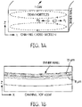
- Figure 1A is a schematic diagram of a microfluidic channel cross-section illustrating the principle of inertial spiral microfluidics.
- the main flow (into the page) follows a curvilinear path leading to the development of secondary flows, known as Dean vortices (dashed lines).
- Dispersed particles experience a combination of lift forces ( F L ) and Dean forces ( F D ) , which result in differential migration of the particles to unique equilibrium positions near the inner wall.
- the lift forces go as F L ⁇ a p 4 and the Dean forces go as F D ⁇ a p , where a p is particle diameter.
- the equilibrium position is thus particle-size-dependent, with larger particles (dominated by F L ) aligning near the inner wall and smaller particles (dominated by F D ) near the channel center 47 .
- An example of a two-particle separation in a microfluidic spiral is shown in Figure 1B . Particles of one size (e.g. , 15 ⁇ m) are separated from particles of a different size ( e.g. , 8 ⁇ m) at a flow rate of 1 mL/min.
- Spiral inertial microfluidic devices have been successfully used in a wide range of applications including particle 47,49,51,54 and cell 49 separations, cell synchronization, 50 circulating tumor cell isolation, 59 and electroporation. 55 These devices typically utilize a branched outlet to collect the concentrated, focused particle or cell streams.
- the separation efficiency for a device is defined as the number of targeted particles collected at a single outlet over the number of those particles input into the device.
- the concentration factor is defined as the concentration of particles, assuming 100% recovery, over the inlet partial concentration multiplied by the separation efficiency.
- the concentration factor is limited by the number of outlets: if there are too many, a particle stream cannot be precisely controlled to flow through a single one.
- centrifugal forces dominated and pushed particles to the outside wall of the curvilinear channels.
- Another design took advantage of centrifugal forces to push blood cells against the outer wall and remove plasma from a waste channel on the inner wall. 38 Flow rates up to 120 ⁇ L/min were achieved.
- inertial lift forces focused targeted cells away from the walls, creating a target-free region where waste channels removed fluid and non-targeted cells 69,70 ; this design achieved > 500 ⁇ L/min.
- WO 2011/109762 A1 discloses a fluid processing apparatus having the features of the preamble of claim 1.
- this fluid processing apparatus is a microfluidic sorter which has a spiral channel separator having an inlet in the center and a plurality of outlets at the periphery.
- US 2009/0283474 A1 discloses a device for extracting a liquid phase from a suspension.
- the device comprises: a main duct for conveying a flow of said suspension, the duct being of a length that is sufficient to enable a layer of said suspension to develop that is depleted in solid phase; flow disturbance means for disturbing the flow of said suspension, said means being provided in the main duct and being adapted to cause at least one recirculation vortex to form so as to increase locally the thickness of said depleted layer; and liquid extraction means disposed in a region of the device where said suspension is enriched in liquid phase as a result of said recirculation vortex.
- FR 2 918 900 A1 discloses a device for separating a liquid suspension.
- the device comprises a continuous liquid phase and at least one dispersed phase, the phases having different densities.
- the device comprises a first duct with at least one curved section, at least one second duct also with a curved section, running parallel to said first duct on the outside of the curve of the latter and at least one chamber separating the first and second ducts and in turn being curved.
- a longitudinal slot is arranged in the chamber running along the curved section of the chamber and communicating between the first and second ducts such as to permit the exchange of material between them.
- the slot is arranged at the center of the chamber.
- EP 2 127 752 A2 discloses a particle separation system.
- the system comprises a plurality of individual curved particle separation devices stacked parallel to one another; an inlet coupler connected to all inlets of the devices, the inlet couple being operative to facilitate input of fluid to all inlets of the plurality of individual curved particle separation devices; and at least two outlet couplers connected to the corresponding outlets of the plurality of individual curved particle separation devices.
- the present invention relates to methods of separating particles within samples, for example, separating target DNA, from mixed DNA in a sample.
- the target DNA is present in target organisms, such as viruses, bacteria (prokaryotes), fungi or combinations thereof.
- the mixed DNA includes target DNA and non-target DNA.
- the non-target DNA is mammalian DNA.
- the sample contains cells having nuclei.
- the cells are mammalian cells.
- the separated target organisms are treated to release their DNA which can be recovered.
- a method of separating a component of interest from a sample comprising introducing the sample to a spiral inertial filtration device as provided herein.
- the spiral inertial filtration device comprises at least one waste channel configured to draw particle-free fluid from the device, thereby increasing the particle concentration of fluid (sample) remaining in the device.
- the waste channels reduce the volume of the sample from about 10% to about 95%, ie. about 10%, about 15%, about 20%, about 25%, about 30%, about 35%, about 40%, about 45%, about 50%, about 55%, about 60%, about 65%, about 70%, about 75%, about 80%, about 85%, about 90%, or about 95%.
- the component of interest is concentrated by the spiral inertial filtration device.
- the component of interest is selected from viruses, bacteria, fungi, cancer cells, and white blood cells.
- the component of interest is neutrophils.
- One embodiment of the present invention provides a spiral inertial filtration device as described herein.
- Another embodiment of the present invention provides a spiral inertial filtration device as described herein, wherein the device concentrates and/or filters more than one component of interest from the same sample.
- a further embodiment of the present invention provides a method of concentrating and/or filtering more than one component of interest from a sample using a spiral inertial filtration device as provided herein.
- This description may use relative spatial and/or orientation terms in describing the position and/or orientation of a component, apparatus, location, feature, or a portion thereof. Unless specifically stated, or otherwise dictated by the context of the description, such terms, including, without limitation, top, bottom, above, below, under, on top of, upper, lower, left of, right of, in front of, behind, next to, adjacent, between, horizontal, vertical, diagonal, longitudinal, transverse, etc., are used for convenience in referring to such component, apparatus, location, feature, or a portion thereof in the drawings and are not intended to be limiting.
- the present invention relates to methods of separating particles, such as target DNA, from mixed DNA in a sample.
- the target DNA is present in target organisms.
- the target organisms may be viruses, bacteria (prokaryotes), fungi or combinations thereof.
- the mixed DNA includes target DNA and non-target DNA.
- the non-target DNA is mammalian DNA.
- the sample contains cells having nuclei.
- the cells are mammalian cells.
- the separated target organisms are treated to release their DNA which can be recovered.
- the present invention provides a method of increasing the concentration factor of spiral inertial microfluidics while relaxing the requirements for the number of branched outlets, through a new approach known as S piral I nertial F il T ration (SIFT).
- SIFT S piral I nertial F il T ration
- This technique utilizes the focusing behavior of inertial microfluidics in a main microfluidic channel having a spiral geometry to create a large particle-free flow region from which a large fraction of particle-free (or substantially particle free) fluid can be "skimmed" through one or more waste channels, or secondary channels, extending from one or more portions of the main channel.
- the major drawback of skimming techniques described above is that the performance drops at increased flow rates.
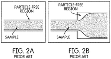
- particles are instead focused near the inner wall, creating a large particle-free region at the outer wall (as shown in Figure 3 ).
- fluid can be removed from this particle-free region, thus increasing the concentration of the particles in the main microfluidic channel.
- the particle streams are minimally disrupted by removing large amounts of fluid.
- FIG. 4 is a schematic diagram of a spiral inertial filtration (SIFT) device embodying aspects of the invention.
- the device includes an inlet at which a fluid containing particles of one or more sizes is introduced into the device, a microfluidic, main channel coiled in a spiral configuration, and one or more outlets.
- the device includes five outlets 01-05. In practice, however, the device may have fewer than or more than five outlets.
- the inlet is located at an inner part of the spiral configuration of the main channel, and the outlets 01-05 are located at an outer end portion of the spiral configuration.
- Fluid particles within the fluid segregate into separate, focused streams, according to the size of the particle, as explained above, thereby creating substantially particle-free regions within the fluid flowing through the main channel.
- Fluid particle-free or substantially particle-free
- the illustrated embodiment include six secondary channels W1-W6.
- the device may have fewer than or more than six secondary channels.
- the waste channels extend radially outwardly from the outermost loop of the spiral configuration. Concentrated particle streams, each comprising particles of a different size, are collected through one of outlets 01-05.
- the device may be fabricated from a material such as polydimethylsiloxane (PDMS) prepolymer, examples of which are described in further detail below.
- PDMS polydimethylsiloxane
- Other suitable materials include thermal plastics (e.g., Poly(methyl methacrylate) (“PMMA”), or Cyclic Olefin Copolymer (“COC”)) and glass/silicon.
- the particle, or component, of interest does not readily migrate to a unique equilibrium position under the effects of lift forces ( F L ) and/or Dean forces ( F D ), and thus does not focus into a discrete particle stream as shown in Figure 1B .
- lift forces F L
- Dean forces F D
- non-focused components can be collected through the secondary channels and can be focused by other means and removed from the waste fluid.
- the SIFT design concept presented in Figure 4 is capable of recovering a targeted particle size with nearly perfect separation efficiency and concentrating the targeted particles by more than an order of magnitude while operating at a sample processing rate of 1 mL/min.
- aspects of the invention include the development of equations for designing a SIFT device for specific fluid removal. Validation of the design equations was demonstrated by removal of a desired fraction of the sample fluid (without removing targeted particles) by controlling the channel geometries. The experimental results demonstrated that the amount of fluid removed from the sample is limited by changes in particle position and particle stream width caused by decreases in the linear velocity in the channel, U ⁇ , and the Dean number, De, as fluid is removed.
- aspects of the invention further include the determination that the limitations on larger fluid removal rates can be overcome by correcting the main channel geometry to maintain U ⁇ or De following fluid removal through a waste channel.
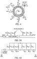
- FIG. 5A is a schematic diagram of a fluidic network including a main channel and a plurality of waste, or secondary, W 1 -W n channels.
- a schematic of the equivalent electrical circuit is shown in Figure 5B .
- the subscripts "m” and “s” represent the main channel and secondary channels, respectively.
- the flow rate at the inlet of the device is analogous to a current source, and all outlets are terminated at ground, as they have the same pressure.
- a volumetric flow ratio, r Qj of the main channel ( Q m,j ) to a side waste channel at the j th node ( Q s,j )
- R s,j and R m,j are the resistances of the waste channel and main channel at the j th node, respectively
- R s,j-1 is the resistance of the waste channel at the previous node j-1
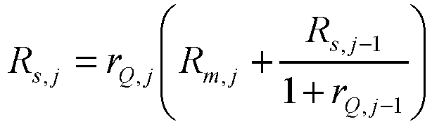
- Equation (4) illustrates that once r Qj is specified, the resistance of the waste channel, R s,j , at any node is determined only by the resistance in the main channel, R m,j , the resistance of the previous waste channel, R s,j-1 , and the flow ratio of the previous waste channel, r Qj-1 . Using this relationship, the resistance required to achieve a specified fluid removal can be determined, and from that relationship, the geometry, e.g. , the width, of the secondary waste channel can be determined.
- the channel dimensions can be calculated.
- ⁇ is the fluid dynamic viscosity
- w , h , and L are the width, height, and length of the channel.
- Equation (6) illustrates that the fluidic resistance of a waste channel can be controlled by changing its width.
- amount of fluid drawn through a secondary channel can be controlled by the width of the secondary channel, which is given by the formula: w ⁇ 12 ⁇ L h 3 R H + 0.63 h .
- L arc ⁇ R 180 , where ⁇ is the angle in degrees and R is the radius of curvature.
- Equation (7) is only valid for the case of w > h .
- a thin channel may be required, and thus the width may be less than the height.
- the full Equation (5) should be solved to determine the width, which requires a numerical solver.
- the waste channel width is set in order to remove a targeted fraction of the sample fluid.
- a spiral inertial filtration device can be designed for the removal of a specific fraction of the inlet fluid.
- the relative volumetric flow rates through the main ( Q m ) and secondary channel ( Q s ) are achieved by properly balancing the fluidic resistances in the channels.
- the fraction of fluid removed from a SIFT device can be controlled by designing for a specific flow ratio, r Q,j , at each waste channel, which is achieved by properly balancing the fluidic resistances.
- the waste channel was located at the W2 position (See Figure 4 ).
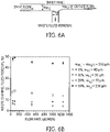
- a schematic of the waste channel is shown in Figure 6A .
- the width of the waste channel, w s,j was set to control the amount of fluid removed from the main channel.
- the main channel width prior to the waste channel, w m,j , and the main channel width after the waste channel, w m,j-1 were both 250 ⁇ m.
- Figure 6B shows the percentage of fluid removed through the waste channel as a function of inlet volumetric flow rate for devices designed for the removal of 5%, 10%, 20% , or 50% of the inlet fluid.
- the widths of the main channel w m and the waste, or secondary, channels w s in ⁇ m are listed for each of the devices.
- the width of the main channel, w m,j , before the waste channel is equal to the width of the main channel after the waste channel, w m,j - 1 for each graph presented in Figure 6B .
- the width of the waste channel, w s j is shown as being different for each graph in response to the amount of fluid removed from the main channel._ Specifically, the width of the main channel, w m,j , before the waste channel and after the waste channel, w m,j-1 , is 250 ⁇ m. Errors bars indicate the standard deviation across three experiments for a single device. To measure variation due to fabrication, two conditions were tested with duplicate devices: 20% fluid removal at 50 ⁇ L/min and 10% fluid removal at 1000 ⁇ L/min. The 20% results agreed to within 1.5%, and the 10% results were within 0.5%.
- the fraction of fluid removed was within 2% of the designed value. With increasing flow rate, the fraction decreased, flattening at 1000 ⁇ L/min, although the removal rates were still within 6%.
- the fluid removal rate should be independent of flow rate.
- the flow rate dependence was attributed to the elasticity of the PDMS. It is known that deformation of PDMS microchannels occurs under pressure-driven flow, causing changes in the channel height and width 73,74 . The design equations did not account for this behavior. As a result, for the flow rates at which operation was desired (> 750 ⁇ L/min), the fluid removal rates were different than what was designed.
- the widths of the waste channels could be adjusted to account for PDMS deformation, or other materials can be used that do not swell under pressure, such as thermal plastics.
- Equation (7) was used to design these devices even though for the 5% removal width, w , of the waste channel is less than height, h, of the waste channel so this approximation was not valid.
- the difference in widths calculated by solving Equation (5) and Equation (7) is 5 ⁇ m. Given the fabrication tolerances ( see above), a 5 ⁇ m difference in the widths was deemed to be acceptable.
- Figure 6B shows 5% fluid removal to within ⁇ 1.5%.
- a series of SIFT microfluidic devices with a single waste channel were fabricated. These devices consisted of a 7-loop Archimedean spiral (inner radius of 0.5 cm) with a single inlet, a waste channel, and a bifurcating outlet. In this non-limiting example, the spiral channel was 250 ⁇ m ⁇ 50 ⁇ m (w ⁇ h) and had a 250 ⁇ m gap between successive loops.
- the evaluation design chosen is not intended to be limiting.
- the invention may be implemented with main channel conigurations having fewer than or more than seven loops or configurations other than an Archimedean spiral of the stated dimensions.
- the widths of the waste channels were set between 40 and 250 ⁇ m to remove a certain fraction of fluid: e.g., 5, 10, 20, or 50%.
- a certain fraction of fluid e.g., 5, 10, 20, or 50%.
- the flow removed by a waste channel depends on its fluidic resistance, which is proportional to the channel length divided by its width.
- the soft lithography technique that was used achieved widths within 2-5 ⁇ m of the designed widths. Therefore, to distinguish devices designed to remove different amounts of fluid, the waste channel widths needed to differ by more than 5 ⁇ m.Ensuring this tolerance necessitated a waste channel length of 19 mm, which was fit compactly next to the spiral using a meander path ( see Figure 4 ).
- each of the waste channels was 35 ⁇ m wide, 50 ⁇ m high, and 19 mm in long.
- the goal of the SIFT device containing six waste channels and five outlets was to achieve fluid removal rates r Q larger than an order of magnitude.
- For W3-W6 r Q was 5, and for W1 and W2 r Q was 10.
- the five outlets, each having an r Q of 4 were used to further increase the amount of fluid separated from the recovered particles.
- Table 1 lists the r Q and the calculated fraction of fluid removed from the waste channels, x s,j,ca / c , wherein the subscript "s" refers to secondary, or waste, channels.
- the waste channel width, w s,j,ca / c , required to achieve these r Q was calculated.
- the w s,j,calc must be greater than h (50 ⁇ m); if not, the error from using the approximation was > 10 ⁇ m.
- w s,j,calc would be ⁇ h (50 ⁇ m), and so the full Equation (5) was solved to calculate w s,j,calc (see below for a discussion on using Equation (5) for w > h and w ⁇ h ).
- the w s,j,calc are listed in Table 1.
- the devices were fabricated using standard soft lithography.
- a 10:1 mixture of polydimethylsiloxane (PDMS) prepolymer and curing agent (Sylgard 184, Dow Corning) was cast over a silicon master mold and cured at 50 °C for two hours.
- the master mold was formed by spin coating photoresist (Shipley 1813) onto a silicon wafer to a thickness of 3 ⁇ m, pre-baking for 1 min at 95 °C, and exposing to 365 nm UV for 13 s.
- the photoresist was developed for 75 sec. in Microposit developer CD-30 (Shipley).
- the wafer was then etched at a rate of ⁇ 2 ⁇ m/min with deep reactive ion etching (DRIE) using the photoresist as the mask.
- the resist was stripped using Remover PG (MicroChem Corp.).
- the silicon mold was silanized with trichloro1H, 1H, 2H, 2H-perfluorooctyl)silane (Sigma Aldrich) using vapor deposition. Inlets and outlets were punched into the PDMS substrate, and it was sonicated in isopropanol for 90 min to remove PDMS debris and dust.
- the PDMS substrate was placed on an 85 °C hotplate for 2 hrs to remove the isopropanol and was then irreversibly bonded to glass using O 2 plasma (13 seconds at 0.75 Torr and 50 mW).
- Tygon tubing (0.02" I.D., 0.06" O.D.) was inserted into the inlet and outlets of the bonded devices.
- deionized water was pumped into the devices at particular flow rates using a syringe pump (New Era Pump Systems, Inc.). To ensure that the flow rate had stabilized, each rate was held for 5 minutes. Fluid was then collected from the waste channels and the outlets for 5 min and the fluid was weighed to determine the volume collected. This was repeated three times for each flow rate for a single device.
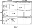
- Figure 7 represents images of 15 ⁇ m particles focused in SIFT devices containing a single waste channel designed for 5% ( i and ii ) , 20% ( iii and iv ), and 50% ( v and vi ) fluid removal at two flow rates (100 ⁇ L/min and 1250 ⁇ L/min).
- the flow rates selected for experiment and verification are not intended to be limiting. Flow rates different from 100 ⁇ L/min or 1250 ⁇ L/min may be used and higher flow rates, e.g., up to 3 mL/min. may be employed.
- Figure 7 showed that one can design for specific fluid removal rates; however, it is important to determine the impact of the fluid removal on the concentration and position of focused particle streams.
- Fluorescent particles 15 ⁇ m in diameter (14% coefficient of variation (CV)) (ThermoFisher Scientific) dispersed in deionized water at a concentration of 0.003% by weight were injected at increasing flow rates into the spiral inertial filtration devices containing a single waste channel of varying width using the syringe pump. Images of the focused particles were taken using an inverted fluorescence microscope (Olympus Corporation, model IX51) equipped with a 12-bit digital CCD camera (Hamamatsu Photonics, model ORCA-03G). Three-second exposures were used to create visible particle traces. A sequence of 15 images was overlaid to create a composite image. To visualize the channel walls, a bright field image was taken, the image was inverted (converted to a negative) using ImageJ (U.S. National Institutes of Health), and the image was overlaid onto the particle focusing composite to create the final image.
- CV coefficient of variation
- the position shift is likely due to distortions in the fluid streamlines caused by the large fluid removal rates, drawing the particle stream toward the waste channel.
- the impact of the waste channel on the particle stream decreased because the particles occupied streamlines closer to the inner wall, which are less affected by the waste channel ( Figure 7 iv ).
- the width of the streamlines increases, causing a further increase in the width of the particle stream.
- U f and De must be maintained by modifying conditions of the main channel flow downstream of the waste channel. This can be most easily accomplished by changing the width of the main channel following the waste channel.
- U f and De have different dependences on the channel width and cannot be simultaneously corrected. As a result, the effect of correcting each individually was investigated to determine which parameter had the largest impact on focusing.
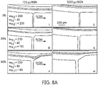
- FIG. 8A represents particle focusing results for SIFT devices with the main channel widths corrected to maintain Dean number, De, following fluid removal from a single waste channel.
- Figure 8A shows the particle stream at fluid removal rates of 5, 20, and 50% at 100 ⁇ L/min and 1250 ⁇ L/min.
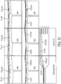
- Figure 8B shows the results of focusing 15 ⁇ m fluorescent particles in devices designed to maintain fluid velocity, U f , following fluid removal from a single waste channel.
- the waste channel had little to no effect on the particle stream for 5% removal ( See Figures 8Bi and ii ) and 20% removal ( See Figures 8B iii and iv ).
- the results were similar to those obtained for maintaining De ( compare Figures 8A i , ii, iii, iv ) because w m,j-1 corrected for De and U f for 5% removal and 20% removal differed by only 4% and 7%, respectively.
- the w m,j-1 was 36% larger for the U f correction than for the De correction.
- Figure 8 shows that correcting for either De or U f eliminated particle loss through the waste channel and improved focusing after the waste channel.
- U f correction prevented particle stream dispersion at the waste channel ( Figure 8B ).
- the particle stream maintained its trajectory at a normalized particle position of 0.45.
- the corrected width for U f is wider than for De, more fluid can be removed from sequential waste channels without negatively affecting particle focusing and separation.
- the main channel of the device may have a non-uniform height varying along the length of the main channel so that the channel geometry could be varied to maintain a substantially constant De or U f by varying the height instead of, or in addition to, varying the width.
- the height of the main channel is substantially constant between each two neighboring secondary channels.
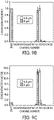
- Figure 9A represents fluorescent images showing the separation of two particle sizes, 4.8 ⁇ m and 8 ⁇ m, in a SIFT device designed for removal of 93% of the inlet fluid.
- the two particle sizes were completely separated at W6 ( Figure 9A i ).
- the main channel width correction main channel width after the waste channel is smaller than before the waste channel
- the particle streams were not impacted by the waste channels.
- Figure 9A ii Due to the change in the aspect ratio and the decreased particle confinement, the separation between the two particle streams decreased, but the two sizes were still clearly separated.
- the channel was expanded ( Figure 9A iii ) to allow for the two particle streams to be separated into different outlets, with the 8 ⁇ m (red) particles flowing out of O1 and the 4.8 ⁇ m particles out of 02 ( Figure 9A iv ).
- the derivation begins with the resistance of the first (right-most in Error! Reference source not found.9) leg of the main channel R m,1 and the resistance of the first side waste channel, R s,1 .
- V IR
- ⁇ P QR
- ⁇ P s,1 ⁇ P m, 1 because they both start at the same point, and thus have the same pressure on their left sides, and both end at the same point, which is atmospheric pressure (or ground) on their right sides.
- r Q,1 Q m , 1 / Q s , 1 ,
- the resistance of the third side waste channel, R s,3 is found in the same manner.
- ⁇ P EQm,3 Q m , 3 R EQ , 3
- Equation (5) For Equation (5) to be valid, the width of the channel, w , must be greater than the height, h . As previously discussed, for some cases Equation (5) can be simplified to Equation (7). Whether Equation (7) is valid will depend on the specific parameters of the system.
- Equation (5) For w ⁇ h, a variation of Equation (5) can be used.
- the hydraulic resistance of a rectangular channel depends on its cross-sectional area, so the resistance of a rectangular channel with dimensions w ⁇ h is the same as that of a channel with " w " and "h" reversed. In other words, rotating a rectangular channel by 90 ° does not change its resistance.
- Equation (5), Equation (7), and Equation (30) could be used for widths w ranging from 10 ⁇ m to 200 ⁇ m ( i.e. aspect ratios ranging from 0.2 to 4).
- Equation (5) instead of Equation (29) was compared with Equation (5) instead of Equation (29) to 0.5.
- Equation (5) and Equation (29) differed by less than 3%, so they could be used interchangeably. In other words, for w ⁇ h both Equation (5) and Equation (29) were valid. Beyond these aspect ratios, the correct equation, either Equation (5) or Equation (29) must be used.
Landscapes
- Chemical & Material Sciences (AREA)
- Health & Medical Sciences (AREA)
- Chemical Kinetics & Catalysis (AREA)
- Analytical Chemistry (AREA)
- General Health & Medical Sciences (AREA)
- Life Sciences & Earth Sciences (AREA)
- Clinical Laboratory Science (AREA)
- Hematology (AREA)
- Dispersion Chemistry (AREA)
- Biochemistry (AREA)
- Physics & Mathematics (AREA)
- General Physics & Mathematics (AREA)
- Molecular Biology (AREA)
- Pathology (AREA)
- Immunology (AREA)
- Biomedical Technology (AREA)
- Engineering & Computer Science (AREA)
- Physical Or Chemical Processes And Apparatus (AREA)
- Apparatus Associated With Microorganisms And Enzymes (AREA)
- Separation Of Solids By Using Liquids Or Pneumatic Power (AREA)
- Sampling And Sample Adjustment (AREA)
- Measuring Or Testing Involving Enzymes Or Micro-Organisms (AREA)
- Micro-Organisms Or Cultivation Processes Thereof (AREA)
Claims (26)
- Fluidbehandlungsvorrichtung, die aufgebaut ist zum Separieren von Partikeln aus einem Fluid, das durch die Vorrichtung fließt, wobei die Vorrichtung Folgendes aufweist:einen Fluideinlass, der so aufgebaut ist, dass er ein Fluid empfängt, das Partikel mit einer oder mehreren Partikelgrößen enthält;einen Hauptfluidkanal, der sich von dem Fluideinlass erstreckt und in einer Spiralkonfiguration angeordnet ist und so aufgebaut ist, dass er eine Differenzialmigration von Partikeln innerhalb des Fluides bewirkt, das durch den Hauptfluidkanal strömt, zu einzelnen Gleichgewichtspositionen innerhalb des Hauptkanals gemäß der Größe des Partikels, wodurch ein oder mehrere Partikelströme und ein partikelfreier Bereich innerhalb der Fluidströmung durch den Hauptkanal ausgebildet werden;einen oder mehrere Auslässe in Fluidkommunikation mit dem Hauptfluidkanal und so aufgebaut, dass er/sie Partikel von einem Partikelstrom empfängt/empfangen, der von dem Hauptfluidkanal strömt; undeinen oder mehrere rechtwinklige Sekundärkanäle, der/die sich von einer Seite des Hauptfluidkanals entlang einer Länge des Hauptfluidkanals zwischen dem Fluideinlass und dem einen oder mehreren Auslässen erstreckt/erstrecken und so aufgebaut ist/sind, dass er/sie zumindest einen Anteil des Fluides von dem partikelfreien Bereich innerhalb des Hauptkanals ansaugt/ansaugen, um die Konzentration von Partikeln innerhalb des verbleibenden Fluides zu erhöhen, das durch den Hauptkanal strömt, wobei der Hauptkanal eine ungleichförmige Geometrie hat, wobei die Geometrie des Abschnittes des Hauptkanals stromabwärtig von einem Sekundärkanal eine verringerte Breite hat, um ein geringeres Fluidvolumen in dem Hauptkanal zu kompensieren, das aus einem Fluidentfernen über den Sekundärkanal herrührt;wobei die Breite jedes Sekundärkanals zwischen 40 und 250 µm beträgt.
- Fluidbehandlungsvorrichtung gemäß Anspruch 1, wobei zumindest:(a) die Sekundärkanäle so aufgebaut sind, dass sie einen Anteil des Fluides des partikelfreien Bereiches von dem Hauptkanal ansaugen, um das Volumen des Fluides, das durch den Hauptkanal strömt, um ungefähr 10 bis 95% zu reduzieren;(b) jeder Sekundärkanal sich von einem Außenrand eines äußersten Ringes der Spiralkonfiguration des Hauptkanals erstreckt;(c) jeder des einen oder der mehreren Sekundärkanäle so aufgebaut ist, dass er von 5 bis 50% des Fluides angesaugt, das durch den Hauptkanal strömt; und/oder(d) jeder Sekundärkanal einen Mäanderpfad aufweist.
- Fluidbehandlungsvorrichtung gemäß Anspruch 1, wobei das durch die Vorrichtung strömende Fluid eine Probe aufweist und die Partikel mehr als eine Komponente von Interesse innerhalb der Probe aufweist, und wobeider Fluideinlass so aufgebaut ist, dass er die Probe empfängt;der Hauptfluidkanal so aufgebaut ist, dass die Komponenten von Interesse zu mehr als einem Komponentenstrom gemäß der Größe der Komponenten fokussiert werden, wodurch ein komponentenfreier Bereich innerhalb des Fluides ausgebildet wird, das durch den Hauptkanal strömt;die Vorrichtung mehr als einen Auslass in Fluidkommunikation mit dem Hauptfluidkanal aufweist und so aufgebaut ist, dass die Komponenten von Interesse von den Komponentenströmen empfangen werden, die von dem Hauptfluidkanal strömen, um jede der Komponenten von Interesse aus der Probe zu filtern; undder eine oder die mehreren Sekundärkanäle so aufgebaut ist/sind, dass er/sie zumindest einen Anteil des Fluides aus dem komponentenfreien Bereich innerhalb des Hauptkanals ansaugt/ansaugen, um die Konzentration von Komponenten von Interesse innerhalb des restlichen Fluides zu erhöhen, das durch den Hauptkanal strömt.
- Fluidbehandlungsvorrichtung gemäß Anspruch 1, wobei der Fluideinlass an einem Innenendabschnitt der Spiralkonfiguration des Hauptkanals angeordnet ist, der eine oder die mehreren Auslässe an einem Außenendabschnitt der Spiralkonfiguration des Hauptkanals angeordnet ist/sind, und der eine oder die mehreren Sekundärkanäle sich radial nach außen von einer Außenschleife der Spiralkonfiguration des Hauptkanals erstreckt/erstrecken.
- Fluidbehandlungsvorrichtung gemäß Anspruch 1, wobei zumindest: (a) die Fluidbehandlungsvorrichtung zumindest zwei Sekundärkanäle aufweist, und/oder (b) die Breite des Hauptkanals zwischen jeweils zwei benachbarten Sekundärkanälen im Wesentlichen konstant ist.
- Fluidbehandlungsvorrichtung gemäß Anspruch 1, wobei die Geometrie des Hauptkanals folgend einem Sekundärkanal sich ändert, um ein Fluidentfernen über den Sekundärkanal zu kompensieren; und wobei zumindest:(a) die Geometrie des Hauptkanals folgend einem Sekundärkanal sich ändert, um eine konstante oder im Wesentlichen konstante Strömungsgeschwindigkeit innerhalb des Hauptkanals vor und nach dem Sekundärkanal beizubehalten, wobei die Geometrie des Hauptkanals sich ändert durch Ändern der Breite des Hauptkanals, und die neue Breite wm,j des Hauptkanals folgend einem j-ten Sekundärkanal durch die folgende Formel bestimmt wird:
 (b) die Geometrie des Hauptkanals sich folgend einem Sekundärkanal ändert, um eine konstante oder im Wesentlichen konstante Dean-Zahl De innerhalb des Hauptkanals vor und nach dem Sekundärkanal beizubehalten, wobei die Dean-Zahl De durch die folgende Formel angegeben ist: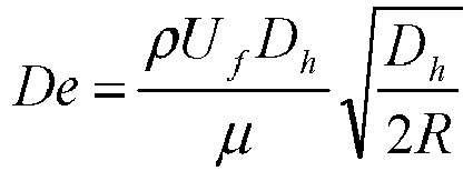
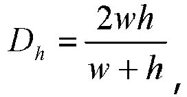 (c) die Geometrie des Hauptkanals sich ändert durch Ändern der Breite des Hauptkanals, wobei eine stromabwärtige Ecke einer Verbindung zwischen dem Hauptkanal und dem Sekundärkanal filetiert ist, um eine allmähliche Änderung der Breite des Hauptkanals zu ermöglichen.
 - Fluidbehandlungsvorrichtung gemäß Anspruch 1, mit zumindest (a) zwischen einem und fünf Auslässen, und/oder (b) zwischen einem und sechs Sekundärkanälen.
- Fluidbehandlungsvorrichtung gemäß Anspruch 1, wobei die Vorrichtung aus Polydimethylsiloxan hergestellt ist.
- Fluidbehandlungsvorrichtung gemäß Anspruch 1, wobei zumindest: (a) die Vorrichtung so aufgebaut ist, dass sie eine Strömungsrate zwischen 100 µl/min und 1250 µl/min speichert, und/oder (b) die Vorrichtung so aufgebaut ist, dass sie Fluid bei einer Rate von 1 mL/min behandelt.
- Fluidbehandlungsvorrichtung gemäß Anspruch 1, wobei der Fluidwiderstand des Sekundärkanals, der erforderlich ist, um Fluid aus dem Hauptkanal bei einer spezifischen Rate zu saugen, die folgende Beziehung erfüllt:
- Fluidbehandlungsvorrichtung gemäß Anspruch 1, wobei die Spiralkonfiguration des Hauptkanals eine 6- oder 7-Schleifenspirale aufweist; wobei:(a) die Fluidbehandlungsvorrichtung einen einzelnen Einlass, einen einzelnen Sekundärkanal und einen in zwei gegabelten Auslass aufweist, wobei der Spiralhauptkanal einen Zwischenraum mit 250 µm zwischen aufeinanderfolgenden Schleifen hat, und wobei die Länge des Sekundärkanals ungefähr 19 mm beträgt; oder(b) die Spiralkonfiguration eine archimedische Spirale ist.
- Fluidbehandlungsvorrichtung gemäß Anspruch 1, wobei zumindest (a) der Hauptkanal eine Breite von ungefähr 250 µm und eine Höhe von ungefähr 50 µm aufweist, und/oder (b) jeder Sekundärkanal eine Breite von ungefähr 35 µm, eine Höhe von ungefähr 50 µm und eine Länge von ungefähr 19 mm aufweist.
- Verfahren zum Filtern und/oder Konzentrieren von Partikeln eines Fluides, das Partikel in einer oder mehrerer Partikelgrößen aufweist, in der Fluidbehandlungsvorrichtung gemäß einem der vorherigen Ansprüche, wobei das Verfahren Folgendes aufweist:Bewegen des Fluides in einem Spiralpfad unter Bedingungen, die eine Differenzialmigration von Partikeln innerhalb des sich bewegenden Fluides zu einzelnen Gleichgewichtspositionen gemäß der Größe des Partikels bewirkten, wodurch einer oder mehrere Partikelströme und ein partikelfreier Bereich innerhalb des sich bewegenden Fluides ausgebildet werden;Ansaugen von zumindest einem Anteil des Fluides aus dem partikelfreien Bereich des sich bewegenden Fluides zu einem rechtwinkligen Sekundärkanal, der sich von einer Seite des Spiralpfades entlang einer Länge des Pfades zwischen einem Fluideinlass und einem oder mehreren Auslässen erstreckt, um die Konzentration von Partikeln innerhalb des Restes des sich bewegenden Fluides zu erhöhen; undSammeln von Partikeln von einem oder mehreren der Partikelströme;dadurch gekennzeichnet, dassdas Verfahren des Weiteren aufweist: Definieren der Breite jedes Sekundärkanals zum Ansaugen eines spezifischen Anteils des Fluides des partikelfreien Bereiches von dem Hauptkanal gemäß der folgenden Formel:

- Verfahren gemäß Anspruch 13, wobei zumindest: (a) der Sammelschritt an dem Ende des Spiralpfades ausgeführt wird; (b) die Partikel von jedem des einen oder mehreren Partikelströmen in Gleichgewichtspositionen gehalten werden durch Anhebekräfte FL und Dean-Kräfte FD; und/oder (c) der Ansaugschritt das Volumen des sich bewegenden Fluides um ungefähr 10 bis 95% reduziert.
- Verfahren gemäß Anspruch 13, wobei die Partikel eine oder mehrere Komponenten von Interesse innerhalb eines Probenfluides aufweisen; und das Verfahren des Weiteren aufweist: Erhöhen der Konzentration jeder Komponente von Interesse.
- Verfahren gemäß Anspruch 13, wobei zumindest (a) die eine oder die mehreren Partikelgrößen in einem Bereich von 4,8 µm bis 15 µm sind, und/oder (b) die Partikel aus einer Gruppe ausgewählt werden, die aus DNA-Molekülen, Viren, Bakterien, Pilzen, Krebszellen, weißen Blutzellen und Neutrophilen besteht.
- Verfahren gemäß Anspruch 13, das des Weiteren aufweist: Ändern der Bedingungen des sich bewegenden Fluides nach dem Ansaugen von zumindest einem Anteil des Fluides aus dem partikelfreien Bereich des sich bewegenden Fluides, um ein Fluidentfernen zu kompensieren; und des Weiteren zumindest aufweist:(a) Ändern der Bedingungen des sich bewegenden Fluides nach dem Ansaugen von zumindest einem Anteil des Fluides aus dem partikelfreien Bereich des sich bewegenden Fluides, um eine Strömungsgeschwindigkeit innerhalb des sich bewegenden Fluides konstant oder im Wesentlichen konstant zu halten vor und nach dem Ansaugen von zumindest einem Anteil des Fluides aus dem partikelfreien Bereich des sich bewegenden Fluides; und/oder(b) Ändern der Bedingungen des sich bewegenden Fluides nach dem Ansaugen von zumindest einem Anteil des Fluides aus dem partikelfreien Bereich des sich bewegenden Fluides, um eine Dean-Zahl konstant oder im Wesentlichen konstant zu halten vor und nach dem Ansaugen von zumindest einem Anteil des Fluides aus dem partikelfreien Bereich des sich bewegenden Fluides.
- Verfahren gemäß Anspruch 13, wobei zumindest: (a) das sich bewegende Fluid eine Strömungsrate von zwischen 100 µl/min und 1250 µl/min aufweist, und/oder (b) das Verfahren aufweist: Filtern und/oder Konzentrieren von Fluid, das Partikel von einer oder mehreren Partikelgrößen enthält, bei einer Rate von 1 ml/min.
- Verfahren gemäß Anspruch 13, wobeider Schritt des Bewegens des Fluides in einem Spiralpfad ausgeführt wird in einem Hauptfluidkanal, der sich von einem Fluideinlass erstreckt und in einer Spiralkonfiguration angeordnet ist;der Schritt des Ansaugens von zumindest einem Anteil des Fluides aus dem partikelfreien Bereich des sich bewegenden Fluides ausgeführt wird in einem oder mehreren Sekundärkanälen, der/die sich von dem Hauptfluidkanal erstreckt/erstrecken; undder Schritt des Sammelns von Partikeln aus einem oder mehreren der Partikelströme ausgeführt wird mit einem oder mehreren Auslässen in Fluidkommunikation mit dem Hauptfluidkanal.
- Verfahren gemäß Anspruch 13, wobei der Hauptkanal eine ungleichförmige Breite hat, die entlang der Länge des Hauptkanals variiert, und der Schritt des Ansaugens von zumindest einem Anteil des Fluides aus dem partikelfreien Bereich des sich bewegenden Fluides ausgeführt wird durch zumindest zwei Sekundärkanäle, wobei die Breite des Hauptkanals zwischen jeweils zwei benachbarten Sekundärkanälen im Wesentlichen konstant ist.
- Verfahren gemäß Anspruch 19, wobei zumindest (a) der eine oder die mehreren Sekundärkanäle sich radial nach außen von einer Außenschleife der Spiralkonfiguration des Hauptkanals erstreckt/erstrecken, und/oder (b) jeder Sekundärkanal sich von einem Außenrand eines äußersten Ringes der Spiralkonfiguration des Hauptkanals erstreckt.
- Verfahren gemäß Anspruch 19, das des Weiteren aufweist: Ändern der Geometrie des Hauptkanals folgend einem Sekundärkanal, um ein Fluidentfernen über den Sekundärkanal zu kompensieren; und des Weiteren mit zumindest:(a) Ändern der Geometrie des Hauptkanals folgend dem Sekundärkanal, um eine Strömungsgeschwindigkeit innerhalb des Hauptkanals konstant oder im Wesentlichen konstant zu halten vor und nach dem Sekundärkanal, und wobei das Verfahren des Weiteren aufweist: Ändern der Geometrie des Hauptkanals durch Ändern der Breite des Hauptkanals, wobei die neue Breite bm,j des Hauptkanals folgend einem j-ten Sekundärkanal bestimmt wird durch die Formel:
 (b) Ändern der Geometrie des Hauptkanals folgend einem Sekundärkanal, um eine Dean-Zahl De innerhalb des Hauptkanals konstant oder im Wesentlichen konstant zu halten vor und nach dem Sekundärkanal, wobei die Dean-Zahl De durch die folgende Formel wiedergegeben wird:
 (c) Ändern der Geometrie des Hauptkanals durch Ändern der Breite des Hauptkanals.
 - Verfahren gemäß Anspruch 13, wobei der Fluidwiderstand eines Sekundärkanals, der Fluid aus dem Hauptkanal bei einer spezifischen Rate saugen soll, die folgende Beziehung erfüllt:

- Verfahren gemäß Anspruch 19 mit des Weiteren zumindest: (a) Sammeln von Partikeln aus jedem Partikelstrom mit zwischen einem und fünf Auslässen; (b) Ansaugen von zumindest einem Anteil des Fluides aus dem partikelfreien Bereich des sich bewegenden Fluides mit zwischen einem bis sechs Sekundärkanälen; und/oder (c) Ansaugen von 5 bis 50% des sich bewegenden Fluides in dem Hauptkanal mit jedem von dem einen oder mehreren Sekundärkanälen.
- Verfahren gemäß Anspruch 19, wobei zumindest: (a) die Spiralkonfiguration des Hauptkanals eine 7-Schleifen-Spirale aufweist, die einen Innenradius von ungefähr 0,5 cm hat, und der Hauptkanal eine Breite von ungefähr 250 µm und eine Höhe von ungefähr 50 µm aufweist;(b) der Spiralhauptkanal einen Zwischenraum von 250 µm zwischen aufeinanderfolgenden Schleifen hat; und/oder(c) die Länge jedes Sekundärkanals ungefähr 19 mm beträgt.
- Verfahren gemäß Anspruch 19, wobei jeder Sekundärkanal eine Breite von ungefähr 35 µm, eine Höhe von ungefähr 50 µm und eine Länge von ungefähr 19 mm aufweist.
Applications Claiming Priority (2)
| Application Number | Priority Date | Filing Date | Title |
|---|---|---|---|
| US201261707878P | 2012-09-28 | 2012-09-28 | |
| PCT/US2013/062672 WO2014052968A1 (en) | 2012-09-28 | 2013-09-30 | Particle separation and concentration using spiral inertial filtration |
Publications (3)
| Publication Number | Publication Date |
|---|---|
| EP2900351A1 EP2900351A1 (de) | 2015-08-05 |
| EP2900351A4 EP2900351A4 (de) | 2016-07-06 |
| EP2900351B1 true EP2900351B1 (de) | 2022-05-25 |
Family
ID=50385555
Family Applications (1)
| Application Number | Title | Priority Date | Filing Date |
|---|---|---|---|
| EP13841066.7A Active EP2900351B1 (de) | 2012-09-28 | 2013-09-30 | Teilchentrennung und -konzentration mittels spiralförmiger inertialer filtration |
Country Status (4)
| Country | Link |
|---|---|
| US (2) | US9804068B2 (de) |
| EP (1) | EP2900351B1 (de) |
| JP (3) | JP6501709B2 (de) |
| WO (1) | WO2014052968A1 (de) |
Families Citing this family (35)
| Publication number | Priority date | Publication date | Assignee | Title |
|---|---|---|---|---|
| JP6265508B2 (ja) | 2012-09-21 | 2018-01-24 | マサチューセッツ インスティテュート オブ テクノロジー | マイクロ流体装置およびその使用 |
| JP6501709B2 (ja) * | 2012-09-28 | 2019-04-17 | キヤノン ユー.エス. ライフ サイエンシズ, インコーポレイテッドCanon U.S. Life Sciences, Inc. | スパイラル慣性濾過を使用する粒子分離及び濃縮 |
| EP3608022A1 (de) | 2013-03-15 | 2020-02-12 | The Trustees of Princeton University | Verfahren und vorrichtungen für reinigung mit hohem durchsatz |
| US11493428B2 (en) | 2013-03-15 | 2022-11-08 | Gpb Scientific, Inc. | On-chip microfluidic processing of particles |
| US20150064153A1 (en) | 2013-03-15 | 2015-03-05 | The Trustees Of Princeton University | High efficiency microfluidic purification of stem cells to improve transplants |
| US12590955B2 (en) * | 2013-03-15 | 2026-03-31 | Zeon Corporation | Methods and systems for processing particles |
| TWI655963B (zh) * | 2013-06-14 | 2019-04-11 | 帕洛阿爾托研究中心公司 | 流體動力分離裝置及流體動力分離方法 |
| US10047344B2 (en) | 2014-02-18 | 2018-08-14 | National University Of Singapore | Biophysically sorted osteoprogenitors from culture expanded bone marrow derived mesenchymal stromal cells (MSCs) |
| CN103923825B (zh) * | 2014-04-17 | 2016-01-13 | 东南大学 | 一种集成细胞分选及检测的微流控芯片系统 |
| ES2839998T3 (es) * | 2014-08-01 | 2021-07-06 | Gpb Scient Inc | Métodos y sistemas para procesar partículas |
| JP2017527299A (ja) * | 2014-09-17 | 2017-09-21 | マサチューセッツ インスティテュート オブ テクノロジー | 灌流バイオリアクター細胞保持のためのマイクロ流体システム及び方法 |
| WO2016044555A1 (en) | 2014-09-17 | 2016-03-24 | Massachusetts Institute Of Technology | System and method for inertial focusing microfiltration for intra-operative blood salvage autotransfusion |
| CA2966623C (en) | 2014-11-03 | 2024-02-20 | The General Hospital Corporation | Concentrating particles in a microfluidic device |
| GB201510189D0 (en) * | 2015-06-11 | 2015-07-29 | Univ Edinburgh | Microfluidic device |
| US10976232B2 (en) | 2015-08-24 | 2021-04-13 | Gpb Scientific, Inc. | Methods and devices for multi-step cell purification and concentration |
| US20170113222A1 (en) * | 2015-10-22 | 2017-04-27 | Owl biomedical, Inc. | Particle manipulation system with spiral focusing channel |
| US11214823B2 (en) | 2015-12-22 | 2022-01-04 | Canon U.S.A., Inc. | Sample-to-answer system for microorganism detection featuring target enrichment, amplification and detection |
| WO2018093475A1 (en) * | 2016-11-15 | 2018-05-24 | Massachusetts Institute Of Technology | Liquid biopsy detection of leukemia using closed-loop microfluidics |
| CN106769361A (zh) * | 2017-01-16 | 2017-05-31 | 大连海事大学 | 一种基于微流控技术的润滑油中颗粒分离的装置及方法 |
| US10543435B2 (en) * | 2017-07-26 | 2020-01-28 | James William Masten, JR. | Low-energy dynamic filter |
| JP7124475B2 (ja) * | 2018-01-17 | 2022-08-24 | 株式会社Ihi | 細胞培養システム及び細胞培養方法 |
| EP4477315A3 (de) | 2018-05-31 | 2025-03-05 | Donaldson Company, Inc. | Tropfensensoren für kraftstoffsysteme |
| JP2020082047A (ja) * | 2018-11-30 | 2020-06-04 | シスメックス株式会社 | 分離成否判定方法、粒子検出方法および粒子分離装置 |
| CN109827806A (zh) * | 2019-03-18 | 2019-05-31 | 中国科学院重庆绿色智能技术研究院 | 一种循环肿瘤细胞的采集装置及方法 |
| JP2021013333A (ja) * | 2019-07-12 | 2021-02-12 | 株式会社Ihi | 微生物選別システム及び微生物選別方法 |
| JP7434740B2 (ja) * | 2019-07-12 | 2024-02-21 | 株式会社Ihi | 検査用サンプル液の調製システム及び検査用サンプル液の調製方法 |
| US12128408B2 (en) | 2019-08-06 | 2024-10-29 | Bio-Rad Laboratories Inc. | Structures on microfluidic devices to control sedimentation |
| CN114901392B (zh) * | 2019-10-21 | 2024-10-29 | 南洋理工大学 | 使用离心力从全血中直接和可扩展地分离循环胞外囊泡 |
| CN110975775A (zh) * | 2019-10-29 | 2020-04-10 | 肇庆市华师大光电产业研究院 | 一种基于迪恩流效应的高通量三维微流体混合装置及其混合方法 |
| EP3971551B1 (de) * | 2020-09-21 | 2026-03-25 | OP-Hygiene IP GmbH | Verfahren zum nachweis einer infektion mittels negativer sortierung |
| KR102474060B1 (ko) * | 2020-10-14 | 2022-12-05 | 한국과학기술연구원 | 미세유체칩 유동에 의한 세포입자의 크기별 분리 장치와 방법 |
| KR20230108294A (ko) | 2020-11-25 | 2023-07-18 | 도날드슨 컴파니, 인코포레이티드 | 최적의 미세채널 길이를 갖는 수리동력학적 분리기 |
| US12478899B2 (en) | 2021-06-02 | 2025-11-25 | Donaldson Company, Inc. | Maintenance of hydrodynamic separators |
| CN113828366A (zh) * | 2021-11-05 | 2021-12-24 | 北华大学 | 微流控芯片 |
| CN116398460A (zh) * | 2023-04-24 | 2023-07-07 | 湖南泛航智能装备有限公司 | 一种透平真空泵离心叶轮转子的动平衡监测系统及方法 |
Family Cites Families (18)
| Publication number | Priority date | Publication date | Assignee | Title |
|---|---|---|---|---|
| US6884360B2 (en) | 2003-07-03 | 2005-04-26 | Sei-Chang Chang | Filtration device with cross-flow function and its filtration method |
| US20070263477A1 (en) * | 2006-05-11 | 2007-11-15 | The Texas A&M University System | Method for mixing fluids in microfluidic channels |
| CN101534917A (zh) | 2006-05-22 | 2009-09-16 | 纽约市哥伦比亚大学理事会 | 采用萃取流体排出流过滤的微流无膜交换系统和方法 |
| US9486812B2 (en) * | 2006-11-30 | 2016-11-08 | Palo Alto Research Center Incorporated | Fluidic structures for membraneless particle separation |
| US8931644B2 (en) * | 2006-11-30 | 2015-01-13 | Palo Alto Research Center Incorporated | Method and apparatus for splitting fluid flow in a membraneless particle separation system |
| US10052571B2 (en) * | 2007-11-07 | 2018-08-21 | Palo Alto Research Center Incorporated | Fluidic device and method for separation of neutrally buoyant particles |
| US8186913B2 (en) * | 2007-04-16 | 2012-05-29 | The General Hospital Corporation | Systems and methods for particle focusing in microchannels |
| WO2008151093A1 (en) | 2007-05-30 | 2008-12-11 | Alburtylab, Inc. | Liquid to liquid biological particle concentrator |
| FR2918900A1 (fr) * | 2007-07-18 | 2009-01-23 | Commissariat Energie Atomique | Dispositif et procede pour la separation des composantes d'une suspension et en particulier du sang |
| FR2931079B1 (fr) * | 2008-05-13 | 2010-07-30 | Commissariat Energie Atomique | Dispositif et procede de separation d'une suspension |
| FR2931080B1 (fr) | 2008-05-13 | 2010-07-30 | Commissariat Energie Atomique | Procede et dispositif d'extraction d'une phase liquide d'une suspension |
| JP4674625B2 (ja) * | 2008-09-25 | 2011-04-20 | 富士ゼロックス株式会社 | 分級装置及び分級方法 |
| US20110070581A1 (en) * | 2009-04-27 | 2011-03-24 | Amit Gupta | Separation of Leukocytes |
| US8208138B2 (en) * | 2009-09-24 | 2012-06-26 | University Of Cincinnati | Spiral microchannel particle separators, straight microchannel particle separators, and continuous particle separator and detector systems |
| SG183468A1 (en) | 2010-03-04 | 2012-09-27 | Univ Singapore | Microfluidics sorter for cell detection and isolation |
| US9149806B2 (en) * | 2012-01-10 | 2015-10-06 | Biopico Systems Inc | Microfluidic devices and methods for cell sorting, cell culture and cells based diagnostics and therapeutics |
| US9327296B2 (en) * | 2012-01-27 | 2016-05-03 | Fenwal, Inc. | Fluid separation chambers for fluid processing systems |
| JP6501709B2 (ja) * | 2012-09-28 | 2019-04-17 | キヤノン ユー.エス. ライフ サイエンシズ, インコーポレイテッドCanon U.S. Life Sciences, Inc. | スパイラル慣性濾過を使用する粒子分離及び濃縮 |
-
2013
- 2013-09-30 JP JP2015534799A patent/JP6501709B2/ja active Active
- 2013-09-30 EP EP13841066.7A patent/EP2900351B1/de active Active
- 2013-09-30 WO PCT/US2013/062672 patent/WO2014052968A1/en not_active Ceased
- 2013-09-30 US US14/042,043 patent/US9804068B2/en active Active
-
2017
- 2017-10-30 US US15/797,704 patent/US10823648B2/en active Active
-
2018
- 2018-12-03 JP JP2018226494A patent/JP7307539B2/ja active Active
-
2021
- 2021-03-05 JP JP2021035334A patent/JP7493473B2/ja active Active
Also Published As
| Publication number | Publication date |
|---|---|
| JP2021102209A (ja) | 2021-07-15 |
| EP2900351A1 (de) | 2015-08-05 |
| JP6501709B2 (ja) | 2019-04-17 |
| JP2019069438A (ja) | 2019-05-09 |
| US10823648B2 (en) | 2020-11-03 |
| JP2015532198A (ja) | 2015-11-09 |
| JP7307539B2 (ja) | 2023-07-12 |
| US9804068B2 (en) | 2017-10-31 |
| US20140093867A1 (en) | 2014-04-03 |
| US20180045626A1 (en) | 2018-02-15 |
| JP7493473B2 (ja) | 2024-05-31 |
| WO2014052968A1 (en) | 2014-04-03 |
| EP2900351A4 (de) | 2016-07-06 |
Similar Documents
| Publication | Publication Date | Title |
|---|---|---|
| EP2900351B1 (de) | Teilchentrennung und -konzentration mittels spiralförmiger inertialer filtration | |
| AU2022203791B2 (en) | Methods and systems for detecting biological components | |
| Wei et al. | Particle sorting using a porous membrane in a microfluidic device | |
| Guo et al. | Deformability based cell sorting using microfluidic ratchets enabling phenotypic separation of leukocytes directly from whole blood | |
| Burke et al. | High-throughput particle separation and concentration using spiral inertial filtration | |
| US8551333B2 (en) | Particle-based microfluidic device for providing high magnetic field gradients | |
| Yamada et al. | Hydrodynamic filtration for on-chip particle concentration and classification utilizing microfluidics | |
| EP3052219B1 (de) | Siebventile, mikrofluidische schaltkreise, mikrofluidische vorrichtungen, kits und verfahren zur isolierung eines analyten | |
| Lin et al. | Highly selective biomechanical separation of cancer cells from leukocytes using microfluidic ratchets and hydrodynamic concentrator | |
| Zheng et al. | Streamline-based microfluidic devices for erythrocytes and leukocytes separation | |
| Jiang et al. | A multilayer lateral-flow microfluidic device for particle separation | |
| Mehendale et al. | A Ra dial Pi llar D evice (RAPID) for continuous and high-throughput separation of multi-sized particles | |
| Chen et al. | Design, fabrication and characterization of nano‐filters in silicon microfluidic channels based on MEMS technology | |
| Chandna et al. | Pillar based microfluidic approach to sorting of microparticle mixtures at various particle ratios | |
| Bayareh et al. | Cancer cell separation using passive mechanisms: A review | |
| US20060204400A1 (en) | Process for separation of dispersions and an apparatus | |
| Parichehreh et al. | Inertial lift enhanced phase partitioning for continuous microfluidic surface energy based sorting of particles | |
| WO2007074906A1 (ja) | マイクロ流体デバイスおよび物質分離方法 | |
| WO2020083984A1 (en) | Fluid refining device | |
| Laki et al. | Microvesicle fractionation using deterministic lateral displacement effect | |
| Bhagat | Inertial microfluidics for particle separation and filtration | |
| Arremsetty | Characterization of a Microscale Cross-Flow Based Split Flow Thin Fractionation (SPLITT) | |
| Huh et al. | Sample clean-up of red fluorescent protein for analysis using electric field in microfluidic device | |
| Raj et al. | Engineering Microfluidics Based Technologies for Rapid Sorting of White Blood Cells | |
| Chen et al. | Integrated Microfluidic Chips for Whole Blood Pretreatment |
Legal Events
| Date | Code | Title | Description |
|---|---|---|---|
| PUAI | Public reference made under article 153(3) epc to a published international application that has entered the european phase |
Free format text: ORIGINAL CODE: 0009012 |
|
| 17P | Request for examination filed |
Effective date: 20150415 |
|
| AK | Designated contracting states |
Kind code of ref document: A1 Designated state(s): AL AT BE BG CH CY CZ DE DK EE ES FI FR GB GR HR HU IE IS IT LI LT LU LV MC MK MT NL NO PL PT RO RS SE SI SK SM TR |
|
| AX | Request for extension of the european patent |
Extension state: BA ME |
|
| DAX | Request for extension of the european patent (deleted) | ||
| RA4 | Supplementary search report drawn up and despatched (corrected) |
Effective date: 20160602 |
|
| RIC1 | Information provided on ipc code assigned before grant |
Ipc: B01D 33/37 20060101AFI20160527BHEP Ipc: A01F 12/44 20060101ALI20160527BHEP |
|
| STAA | Information on the status of an ep patent application or granted ep patent |
Free format text: STATUS: EXAMINATION IS IN PROGRESS |
|
| 17Q | First examination report despatched |
Effective date: 20200807 |
|
| GRAP | Despatch of communication of intention to grant a patent |
Free format text: ORIGINAL CODE: EPIDOSNIGR1 |
|
| STAA | Information on the status of an ep patent application or granted ep patent |
Free format text: STATUS: GRANT OF PATENT IS INTENDED |
|
| INTG | Intention to grant announced |
Effective date: 20211209 |
|
| GRAS | Grant fee paid |
Free format text: ORIGINAL CODE: EPIDOSNIGR3 |
|
| GRAA | (expected) grant |
Free format text: ORIGINAL CODE: 0009210 |
|
| STAA | Information on the status of an ep patent application or granted ep patent |
Free format text: STATUS: THE PATENT HAS BEEN GRANTED |
|
| AK | Designated contracting states |
Kind code of ref document: B1 Designated state(s): AL AT BE BG CH CY CZ DE DK EE ES FI FR GB GR HR HU IE IS IT LI LT LU LV MC MK MT NL NO PL PT RO RS SE SI SK SM TR |
|
| REG | Reference to a national code |
Ref country code: GB Ref legal event code: FG4D |
|
| REG | Reference to a national code |
Ref country code: CH Ref legal event code: EP |
|
| REG | Reference to a national code |
Ref country code: DE Ref legal event code: R096 Ref document number: 602013081736 Country of ref document: DE |
|
| REG | Reference to a national code |
Ref country code: AT Ref legal event code: REF Ref document number: 1494036 Country of ref document: AT Kind code of ref document: T Effective date: 20220615 |
|
| REG | Reference to a national code |
Ref country code: IE Ref legal event code: FG4D |
|
| REG | Reference to a national code |
Ref country code: LT Ref legal event code: MG9D |
|
| REG | Reference to a national code |
Ref country code: NL Ref legal event code: MP Effective date: 20220525 |
|
| REG | Reference to a national code |
Ref country code: AT Ref legal event code: MK05 Ref document number: 1494036 Country of ref document: AT Kind code of ref document: T Effective date: 20220525 |
|
| PG25 | Lapsed in a contracting state [announced via postgrant information from national office to epo] |
Ref country code: SE Free format text: LAPSE BECAUSE OF FAILURE TO SUBMIT A TRANSLATION OF THE DESCRIPTION OR TO PAY THE FEE WITHIN THE PRESCRIBED TIME-LIMIT Effective date: 20220525 Ref country code: PT Free format text: LAPSE BECAUSE OF FAILURE TO SUBMIT A TRANSLATION OF THE DESCRIPTION OR TO PAY THE FEE WITHIN THE PRESCRIBED TIME-LIMIT Effective date: 20220926 Ref country code: NO Free format text: LAPSE BECAUSE OF FAILURE TO SUBMIT A TRANSLATION OF THE DESCRIPTION OR TO PAY THE FEE WITHIN THE PRESCRIBED TIME-LIMIT Effective date: 20220825 Ref country code: NL Free format text: LAPSE BECAUSE OF FAILURE TO SUBMIT A TRANSLATION OF THE DESCRIPTION OR TO PAY THE FEE WITHIN THE PRESCRIBED TIME-LIMIT Effective date: 20220525 Ref country code: LT Free format text: LAPSE BECAUSE OF FAILURE TO SUBMIT A TRANSLATION OF THE DESCRIPTION OR TO PAY THE FEE WITHIN THE PRESCRIBED TIME-LIMIT Effective date: 20220525 Ref country code: HR Free format text: LAPSE BECAUSE OF FAILURE TO SUBMIT A TRANSLATION OF THE DESCRIPTION OR TO PAY THE FEE WITHIN THE PRESCRIBED TIME-LIMIT Effective date: 20220525 Ref country code: GR Free format text: LAPSE BECAUSE OF FAILURE TO SUBMIT A TRANSLATION OF THE DESCRIPTION OR TO PAY THE FEE WITHIN THE PRESCRIBED TIME-LIMIT Effective date: 20220826 Ref country code: FI Free format text: LAPSE BECAUSE OF FAILURE TO SUBMIT A TRANSLATION OF THE DESCRIPTION OR TO PAY THE FEE WITHIN THE PRESCRIBED TIME-LIMIT Effective date: 20220525 Ref country code: ES Free format text: LAPSE BECAUSE OF FAILURE TO SUBMIT A TRANSLATION OF THE DESCRIPTION OR TO PAY THE FEE WITHIN THE PRESCRIBED TIME-LIMIT Effective date: 20220525 Ref country code: BG Free format text: LAPSE BECAUSE OF FAILURE TO SUBMIT A TRANSLATION OF THE DESCRIPTION OR TO PAY THE FEE WITHIN THE PRESCRIBED TIME-LIMIT Effective date: 20220825 Ref country code: AT Free format text: LAPSE BECAUSE OF FAILURE TO SUBMIT A TRANSLATION OF THE DESCRIPTION OR TO PAY THE FEE WITHIN THE PRESCRIBED TIME-LIMIT Effective date: 20220525 |
|
| PG25 | Lapsed in a contracting state [announced via postgrant information from national office to epo] |
Ref country code: RS Free format text: LAPSE BECAUSE OF FAILURE TO SUBMIT A TRANSLATION OF THE DESCRIPTION OR TO PAY THE FEE WITHIN THE PRESCRIBED TIME-LIMIT Effective date: 20220525 Ref country code: PL Free format text: LAPSE BECAUSE OF FAILURE TO SUBMIT A TRANSLATION OF THE DESCRIPTION OR TO PAY THE FEE WITHIN THE PRESCRIBED TIME-LIMIT Effective date: 20220525 Ref country code: LV Free format text: LAPSE BECAUSE OF FAILURE TO SUBMIT A TRANSLATION OF THE DESCRIPTION OR TO PAY THE FEE WITHIN THE PRESCRIBED TIME-LIMIT Effective date: 20220525 Ref country code: IS Free format text: LAPSE BECAUSE OF FAILURE TO SUBMIT A TRANSLATION OF THE DESCRIPTION OR TO PAY THE FEE WITHIN THE PRESCRIBED TIME-LIMIT Effective date: 20220925 |
|
| PG25 | Lapsed in a contracting state [announced via postgrant information from national office to epo] |
Ref country code: SM Free format text: LAPSE BECAUSE OF FAILURE TO SUBMIT A TRANSLATION OF THE DESCRIPTION OR TO PAY THE FEE WITHIN THE PRESCRIBED TIME-LIMIT Effective date: 20220525 Ref country code: SK Free format text: LAPSE BECAUSE OF FAILURE TO SUBMIT A TRANSLATION OF THE DESCRIPTION OR TO PAY THE FEE WITHIN THE PRESCRIBED TIME-LIMIT Effective date: 20220525 Ref country code: RO Free format text: LAPSE BECAUSE OF FAILURE TO SUBMIT A TRANSLATION OF THE DESCRIPTION OR TO PAY THE FEE WITHIN THE PRESCRIBED TIME-LIMIT Effective date: 20220525 Ref country code: EE Free format text: LAPSE BECAUSE OF FAILURE TO SUBMIT A TRANSLATION OF THE DESCRIPTION OR TO PAY THE FEE WITHIN THE PRESCRIBED TIME-LIMIT Effective date: 20220525 Ref country code: DK Free format text: LAPSE BECAUSE OF FAILURE TO SUBMIT A TRANSLATION OF THE DESCRIPTION OR TO PAY THE FEE WITHIN THE PRESCRIBED TIME-LIMIT Effective date: 20220525 Ref country code: CZ Free format text: LAPSE BECAUSE OF FAILURE TO SUBMIT A TRANSLATION OF THE DESCRIPTION OR TO PAY THE FEE WITHIN THE PRESCRIBED TIME-LIMIT Effective date: 20220525 |
|
| REG | Reference to a national code |
Ref country code: DE Ref legal event code: R097 Ref document number: 602013081736 Country of ref document: DE |
|
| PG25 | Lapsed in a contracting state [announced via postgrant information from national office to epo] |
Ref country code: AL Free format text: LAPSE BECAUSE OF FAILURE TO SUBMIT A TRANSLATION OF THE DESCRIPTION OR TO PAY THE FEE WITHIN THE PRESCRIBED TIME-LIMIT Effective date: 20220525 |
|
| PLBE | No opposition filed within time limit |
Free format text: ORIGINAL CODE: 0009261 |
|
| STAA | Information on the status of an ep patent application or granted ep patent |
Free format text: STATUS: NO OPPOSITION FILED WITHIN TIME LIMIT |
|
| PG25 | Lapsed in a contracting state [announced via postgrant information from national office to epo] |
Ref country code: MC Free format text: LAPSE BECAUSE OF FAILURE TO SUBMIT A TRANSLATION OF THE DESCRIPTION OR TO PAY THE FEE WITHIN THE PRESCRIBED TIME-LIMIT Effective date: 20220525 |
|
| REG | Reference to a national code |
Ref country code: CH Ref legal event code: PL |
|
| 26N | No opposition filed |
Effective date: 20230228 |
|
| REG | Reference to a national code |
Ref country code: BE Ref legal event code: MM Effective date: 20220930 |
|
| PG25 | Lapsed in a contracting state [announced via postgrant information from national office to epo] |
Ref country code: SI Free format text: LAPSE BECAUSE OF FAILURE TO SUBMIT A TRANSLATION OF THE DESCRIPTION OR TO PAY THE FEE WITHIN THE PRESCRIBED TIME-LIMIT Effective date: 20220525 |
|
| PG25 | Lapsed in a contracting state [announced via postgrant information from national office to epo] |
Ref country code: LU Free format text: LAPSE BECAUSE OF NON-PAYMENT OF DUE FEES Effective date: 20220930 |
|
| P01 | Opt-out of the competence of the unified patent court (upc) registered |
Effective date: 20230530 |
|
| PG25 | Lapsed in a contracting state [announced via postgrant information from national office to epo] |
Ref country code: LI Free format text: LAPSE BECAUSE OF NON-PAYMENT OF DUE FEES Effective date: 20220930 Ref country code: IE Free format text: LAPSE BECAUSE OF NON-PAYMENT OF DUE FEES Effective date: 20220930 Ref country code: FR Free format text: LAPSE BECAUSE OF NON-PAYMENT OF DUE FEES Effective date: 20220930 Ref country code: CH Free format text: LAPSE BECAUSE OF NON-PAYMENT OF DUE FEES Effective date: 20220930 |
|
| PG25 | Lapsed in a contracting state [announced via postgrant information from national office to epo] |
Ref country code: BE Free format text: LAPSE BECAUSE OF NON-PAYMENT OF DUE FEES Effective date: 20220930 |
|
| PG25 | Lapsed in a contracting state [announced via postgrant information from national office to epo] |
Ref country code: IT Free format text: LAPSE BECAUSE OF FAILURE TO SUBMIT A TRANSLATION OF THE DESCRIPTION OR TO PAY THE FEE WITHIN THE PRESCRIBED TIME-LIMIT Effective date: 20220525 |
|
| PG25 | Lapsed in a contracting state [announced via postgrant information from national office to epo] |
Ref country code: HU Free format text: LAPSE BECAUSE OF FAILURE TO SUBMIT A TRANSLATION OF THE DESCRIPTION OR TO PAY THE FEE WITHIN THE PRESCRIBED TIME-LIMIT; INVALID AB INITIO Effective date: 20130930 |
|
| PG25 | Lapsed in a contracting state [announced via postgrant information from national office to epo] |
Ref country code: CY Free format text: LAPSE BECAUSE OF FAILURE TO SUBMIT A TRANSLATION OF THE DESCRIPTION OR TO PAY THE FEE WITHIN THE PRESCRIBED TIME-LIMIT Effective date: 20220525 |
|
| PG25 | Lapsed in a contracting state [announced via postgrant information from national office to epo] |
Ref country code: MK Free format text: LAPSE BECAUSE OF FAILURE TO SUBMIT A TRANSLATION OF THE DESCRIPTION OR TO PAY THE FEE WITHIN THE PRESCRIBED TIME-LIMIT Effective date: 20220525 |
|
| PG25 | Lapsed in a contracting state [announced via postgrant information from national office to epo] |
Ref country code: TR Free format text: LAPSE BECAUSE OF FAILURE TO SUBMIT A TRANSLATION OF THE DESCRIPTION OR TO PAY THE FEE WITHIN THE PRESCRIBED TIME-LIMIT Effective date: 20220525 |
|
| PG25 | Lapsed in a contracting state [announced via postgrant information from national office to epo] |
Ref country code: MT Free format text: LAPSE BECAUSE OF FAILURE TO SUBMIT A TRANSLATION OF THE DESCRIPTION OR TO PAY THE FEE WITHIN THE PRESCRIBED TIME-LIMIT Effective date: 20220525 |
|
| PG25 | Lapsed in a contracting state [announced via postgrant information from national office to epo] |
Ref country code: BG Free format text: LAPSE BECAUSE OF FAILURE TO SUBMIT A TRANSLATION OF THE DESCRIPTION OR TO PAY THE FEE WITHIN THE PRESCRIBED TIME-LIMIT Effective date: 20220525 |
|
| PG25 | Lapsed in a contracting state [announced via postgrant information from national office to epo] |
Ref country code: BG Free format text: LAPSE BECAUSE OF FAILURE TO SUBMIT A TRANSLATION OF THE DESCRIPTION OR TO PAY THE FEE WITHIN THE PRESCRIBED TIME-LIMIT Effective date: 20220525 |
|
| PGFP | Annual fee paid to national office [announced via postgrant information from national office to epo] |
Ref country code: DE Payment date: 20250820 Year of fee payment: 13 |
|
| PGFP | Annual fee paid to national office [announced via postgrant information from national office to epo] |
Ref country code: GB Payment date: 20250822 Year of fee payment: 13 |