EP2900449B1 - Drehbegrenzer für ventilstift - Google Patents
Drehbegrenzer für ventilstift Download PDFInfo
- Publication number
- EP2900449B1 EP2900449B1 EP13779440.0A EP13779440A EP2900449B1 EP 2900449 B1 EP2900449 B1 EP 2900449B1 EP 13779440 A EP13779440 A EP 13779440A EP 2900449 B1 EP2900449 B1 EP 2900449B1
- Authority
- EP
- European Patent Office
- Prior art keywords
- valve pin
- rail
- finger
- pin
- receiving surface
- Prior art date
- Legal status (The legal status is an assumption and is not a legal conclusion. Google has not performed a legal analysis and makes no representation as to the accuracy of the status listed.)
- Not-in-force
Links
- 239000012530 fluid Substances 0.000 claims description 30
- 238000011144 upstream manufacturing Methods 0.000 claims description 20
- 238000001746 injection moulding Methods 0.000 claims description 6
- 238000002347 injection Methods 0.000 claims description 5
- 239000007924 injection Substances 0.000 claims description 5
- 239000000463 material Substances 0.000 claims description 5
- 238000000034 method Methods 0.000 claims description 5
- 230000000295 complement effect Effects 0.000 description 8
- 238000010168 coupling process Methods 0.000 description 3
- 238000005859 coupling reaction Methods 0.000 description 3
- 230000008878 coupling Effects 0.000 description 1
- 230000005484 gravity Effects 0.000 description 1
Images




Classifications
-
- B—PERFORMING OPERATIONS; TRANSPORTING
- B29—WORKING OF PLASTICS; WORKING OF SUBSTANCES IN A PLASTIC STATE IN GENERAL
- B29C—SHAPING OR JOINING OF PLASTICS; SHAPING OF MATERIAL IN A PLASTIC STATE, NOT OTHERWISE PROVIDED FOR; AFTER-TREATMENT OF THE SHAPED PRODUCTS, e.g. REPAIRING
- B29C45/00—Injection moulding, i.e. forcing the required volume of moulding material through a nozzle into a closed mould; Apparatus therefor
- B29C45/17—Component parts, details or accessories; Auxiliary operations
- B29C45/26—Moulds
- B29C45/27—Sprue channels ; Runner channels or runner nozzles
- B29C45/28—Closure devices therefor
- B29C45/2806—Closure devices therefor consisting of needle valve systems
-
- B—PERFORMING OPERATIONS; TRANSPORTING
- B29—WORKING OF PLASTICS; WORKING OF SUBSTANCES IN A PLASTIC STATE IN GENERAL
- B29C—SHAPING OR JOINING OF PLASTICS; SHAPING OF MATERIAL IN A PLASTIC STATE, NOT OTHERWISE PROVIDED FOR; AFTER-TREATMENT OF THE SHAPED PRODUCTS, e.g. REPAIRING
- B29C45/00—Injection moulding, i.e. forcing the required volume of moulding material through a nozzle into a closed mould; Apparatus therefor
- B29C45/17—Component parts, details or accessories; Auxiliary operations
- B29C45/20—Injection nozzles
- B29C45/23—Feed stopping equipment
- B29C45/231—Needle valve systems therefor
-
- B—PERFORMING OPERATIONS; TRANSPORTING
- B29—WORKING OF PLASTICS; WORKING OF SUBSTANCES IN A PLASTIC STATE IN GENERAL
- B29C—SHAPING OR JOINING OF PLASTICS; SHAPING OF MATERIAL IN A PLASTIC STATE, NOT OTHERWISE PROVIDED FOR; AFTER-TREATMENT OF THE SHAPED PRODUCTS, e.g. REPAIRING
- B29C45/00—Injection moulding, i.e. forcing the required volume of moulding material through a nozzle into a closed mould; Apparatus therefor
- B29C45/17—Component parts, details or accessories; Auxiliary operations
- B29C45/26—Moulds
- B29C45/27—Sprue channels ; Runner channels or runner nozzles
- B29C45/28—Closure devices therefor
- B29C45/2806—Closure devices therefor consisting of needle valve systems
- B29C2045/2875—Preventing rotation of the needle valve
Definitions
- valve pin for preventing a valve pin from rotating around its axis in an injection molding apparatus
- the valve pin is provided with a head that fits into an adapter such that the head cannot rotate within the adapter thus preventing the pin from rotating.
- US 2009/0104307 A1 discloses a valve pin holder that can be coupled to an actuator in an injection molding hot runner.
- the valve pin holder may comprise a number of anti-rotation dowels that extend laterally from the valve pin holder.
- the second end of the finger is slidably engaged with the receiving surface such that the valve pin is movable back and forth along its longitudinal axis while the second end of the finger slides along the receiving surface of the valve pin or the rail.
- the first end of the finger is slidably mounted on or to the rail and the second end of the finger is slidably engaged against the receiving surface of the valve pin.
- the first end of the finger comprises a base portion mounted on or to the rail and the second end of the finger comprises a projection portion having a terminal end, the projection portion being attached to the base portion and projecting radially inward toward the longitudinal axis of the valve pin such that the terminal end of the projection portion slidably engages the receiving surface of the valve pin.
- the base portion is slidably mounted on or to the rail for slidable movement along the axis of the rail.
- the receiving surface of the valve pin comprises a flat on a radially outward surface of the valve pin, and the second end of the finger is slidably engaged against the flat on the radially outward surface of the valve pin.
- the receiving surface of the valve pin comprises a flat on a radially outward surface of the valve pin, the terminal end of the projection engaging the flat of the valve pin.
- the terminal end of the projection comprises a flat that is complementary to the flat of the valve pin.
- the first end of the finger is mounted on or to the valve pin and the second end of the finger is slidably engaged against the receiving surface of the rail.
- the rail has an axially extending slot formed by opposing edge surfaces, the second end of the finger projecting radially outwardly from the longitudinal axis of the valve pin and radially into the slot and slidably engages the opposing edge surfaces.
- a method of limiting or preventing rotation of a valve pin in an injection molding apparatus comprising an injection machine that injects a heated fluid material through an upstream end of a fluid delivery channel towards a downstream end of the fluid delivery channel towards a gate to a cavity of a mold, the method comprising:
- the manifold is mounted such that it is radially slidable with respect to the top clamp plate.
- the top clamp plate is fixedly interconnected to the mold.
- the fluid distribution system includes a manifold, and the valve pin is slidably disposed within a fluid delivery channel disposed within the manifold.
- valve pin has a shaft disposed in the fluid delivery channel of the manifold and a head disposed in a recess of a coupler attached to a drive shaft of the actuator.
- the rail is fixedly interconnected to the manifold.
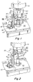
- Figs. 1-2 show a valve pin 10 having a head 20 inserted within a receiving recess 85 of a coupler 80 attached to the drive shaft of an actuator 70 that controllably drives the valve pin along a reciprocal back and forth axial path of travel A along the longitudinal axis A of the valve pin 10.
- the head 20 of the valve pin 10 has a generally cylindrical radially outer surface, but includes a flat radially outer surface portion 25 that is complementary to the end surface 33 of a radial projection 35 that forms a portion of a finger 30.
- the finger has a base portion 37 attached to the projection portion 35, the base portion 37 being slidably mounted to a guide or support rail 40.
- the support rail is mounted along a rail axis A2 that is aligned relative to vale pin axis A to enable the finger to slide back and forth or upstream and downstream together with the back and forth movement of the valve pin 10, head 20 and coupler 80 which are collectively driven along axis A by the actuator 70.
- the guide rail 40 is stationarily mounted relative to the actuator to the top surface 50 of a plate 60 which in the embodiment shown is a heated fluid distribution manifold or hotrunner 60.
- the stationary mounting of the guide rail 40 is enabled by providing the rail 40 with flanged feet 43 that are bolted into the body of the plate 60 on the top surface 50 of the plate 60.
- the guide rail has an elongated body portion 44 substantially parallel to axis A and transverse to the top surface 50 of plate 60.
- the body portion 44 has an elongated slot 45 through which bolts 47 extend, the bolts 47 connecting the base portion 37 of the finger 30 to the body portion 44 of rail 40.
- the bolts 47 are inserted through complementary receiving apertures in the body of the base portion 37 such that the bolts 47 follow any upstream or downstream movement of the finger base portion 37.
- the bolts 47 and the slot 45 and the nuts 49 are all adapted to enable the bolts 47 to slide in an upstream-downstream direction that is generally parallel to the axes A and A2 such that the finger 30 and its projection portion 35 can move back and forth in upstream-downstream manner together with upstream-downstream movement of the pin 10 and pin head 20.
- an undersurface 36 of the finger projection portion 35 will engage an upper facing surface 83 of a portion 81 of the pin head coupler 80. Engagement of the surfaces 36 and 81 causes the finger 30 to move upstream U against the force of gravity together with upstream movement of the coupler 80 with the end surface 33 of the projection portion 35 remaining slidably engaged with the complementary flat surface 25 of the pin head 20.
- the finger 30 is mounted to the stationarily mounted rail 40 in a manner such that the finger 30 is prevented from rotating around any up-down axis.
- the engagement of the end surface 33 of the non-rotatable finger 30 with the complementarily shaped surface 25 of the head 20 acts to limit or prevent rotation R of the valve pin 10 by virtue of its rigid interconnection to the non-rotatable head 20.
- the axially slidable finger 30 follows the upstream-downstream movement of the pin head 20 and surface 25 to prevent the pin head 20 and its attached valve pin 10 from rotating.
- Figs. 3-11 show an alternative embodiment where the anti-rotation finger 30 is a radial projection comprising a rod or pin 30 that has a proximal end that is inserted and stationarily mounted within a complementary receiving aperture 27 that is drilled into the head 20 of the valve pin 10.
- the finger pin 30 is configured and adapted to project radially outwardly RAD toward and through a complementary guide slot 45 that is axially disposed and arranged within the body 44 of guide rail 40 that is stationarily mounted on the top surface 50 of a hotrunner plate 60.
- the guide rail 40 is stationary against rotative movement.
- the finger pin 30 is prevented from rotating and the head 20 is prevented from rotating R around the axis A of the valve pin 10 by virtue of the connection of the finger pin 30 to the head 20.
- the finger pin 30 has an outer surface configuration that is complementary to the inner opposing surfaces 45a, 45b of the slot 45 such that the outer surface 39 of the pin 30 slidably engages surfaces 45a, 45b.
- the guide rail 40 is mounted and arranged such that the slot 45 is disposed to the lateral side of the receiving aperture 85 of the pin head coupler 80.
- the guide rail 40 is mounted and arranged such that the guide slot 45 is disposed in the front of the receiving aperture 85.
- the pin head coupler 80 is fixedly attached to the drive shaft of the actuator 70 and travels and follows the upstream-down A movement of the controllably drivable drive shaft of the actuator 70.
- FIG. 5-11 A third embodiment is illustrated in Figs. 5-11 .
- This embodiment is substantially similar to the second embodiment of Figs. 3-4 wherein the anti-rotation finger 30 is a radial projection stationarily mounted to the head 20 of the valve pin.
- the finger pin 30 is mounted to the head 20 at a different location in the two embodiments.
- the finger pin 30 is offset-mounted radially (laterally) from the pin head axis A, i.e., the pin extends tangentially from the outer cylindrical surface of the pin head.
- the guide rail 40 is mounted such that the slot 45 is disposed to the lateral side of the receiving aperture 85 of the pin head coupler 80.
- the finger pin 30 extends radially (transversely) from the central axis A of the pin head 20, and as a result the guide rail 40 is mounted such that the guide slot 45 is disposed in front of the receiving aperture 85 of the pin head coupler 80.
- This difference in lateral positioning of the finger pin with respect to the pin axis allows for alternative structural arrangements between the adjacent components such the positioning of the rail 40 on the top surface 50 of the manifold 60 or the positioning of the actuator 70 and coupler 80.
- the slot 45 is open-ended at the top end, enabling the distal end 38 of the finger pin 30 to be readily moved in and out of the slot 45 along the rail axis A3.
- the open end of the slot has an enlarged (flared) opening to facilitate positioning of the distal end of the finger pin in the slot 45.
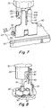
- Figs. 5-8 are different perspective views of the same apparatus.
- the finger pin 30 is in a relatively downstream position, and in Figs. 7-8 in a relatively upstream position.
- Fig. 9 illustrates the apparatus of Fig. 5 disposed in one embodiment of a fluid distribution system, including a top clamp plate 100, manifold 60 and mold 118.
- the top clamp plate is interconnected to the mold, and the manifold is mounted to and between the clamp plate and the mold.
- the top clamp plate has a recess 102, extending completely through the thickness of the clamp plate 100, in which the actuator 70, coupler 80 and pin head 20 are disposed.
- the top clamp plate 100 is spaced apart and disposed substantially parallel to the top surface of the manifold 60.
- This embodiment illustrates a mounting of the top plate and manifold in a manner that enables ready coupling and de-coupling of the valve pin and coupler without requiring disassembly of the top clamp plate from the manifold.
- the actuator 70 is mounted with bolts 72 in the recess 102 of the top clamp plate 100. When the bolts are removed, the actuator can be moved radially within the recess 102 of the top clamp plate, allowing the pin head 20 be radially moved out of the receiving aperture 85 of the coupler 80, thus de-coupling the valve pin from the coupler. With the pin head now located outside the coupler 80, the valve pin can be readily replaced. The actuator 70 (with a new valve pin) can then be moved back (radially) to its original position and bolted to the top clamp plate.
- Fig. 9 also shows a fluid delivery channel 108 in the manifold 60, wherein the valve pin 10 is slidably disposed within the fluid delivery channel disposed within the manifold.
- the valve pin has a shaft 10 that is mounted within and extends through a bushing 110 and mounting aperture in the manifold.
- the downstream distal end of the fluid channel 108 has a gate 114 that communicates with a cavity 116 of a mold 118.
- the pin shaft 10 is adapted to be disposed and driven reciprocally UD within the fluid delivery channel 108 that contains and routes pressurized fluid material into the channel from an injection machine.
- the drive shaft of a motor or actuator comprises a screw which is directly connected at its downstream end with the upstream (proximal) end of the valve pin, to drive the valve pin in the axial direction.
- the proximal end of the valve pin can be connected to and driven by the drive shaft of an actuator in variety of ways.
- the drive shaft of the actuator can be driven by an electric motor.
Landscapes
- Engineering & Computer Science (AREA)
- Manufacturing & Machinery (AREA)
- Mechanical Engineering (AREA)
- Moulds For Moulding Plastics Or The Like (AREA)
- Injection Moulding Of Plastics Or The Like (AREA)
Claims (15)
- Spritzgießsystem mit:einer Einspritzmaschine und einem Fluidverteilungssystem, das ein erwärmtes Fluidmaterial über ein stromaufwärtsseitiges Ende eines Fluidzufuhrkanals (108) in Richtung zu einem stromabwärtsseitigen Ende des Fluidzufuhrkanals (108) und zu einer Öffnung zu einem Hohlraum (116) einer Form (118) einspritzt;einem länglichen Ventilstift (10) mit einer Längsachse (A) und einem proximalen Ende, das mit einem Aktuator (70) verbunden ist, der steuerbar antreibbar ist, um den Stift (10) entlang seiner Längsachse (A) zwischen einer oder mehreren stromaufwärtsseitigen axialen Positionen und einer oder mehreren stromabwärtsseitigen axialen Positionen hin- und hergehend zu bewegen;dadurch gekennzeichnet, dass das System aufweist:eine längliche Schiene (40) mit einer Schienenachse (A3), wobei die Schiene (40) relativ zum Aktuator (70) stationär montiert ist, so dass die Schienenachse (A3) von der Achse (A) des Ventilstifts (10) radial beabstandet ist;einen Finger (30), der zwischen der Schiene (40) und dem Ventilstift (10) hervorsteht, wobei der Finger (30) ein erstes Ende (37, 39) aufweist, das auf oder an einer Komponente unter der Schiene (40) und dem Ventilstift (10) montiert ist, und ein zweites Ende (33, 38), das mit einer Aufnahmefläche (25, 45a, 45b) der anderen Komponente unter der Schiene (40) und dem Ventilstift (10) in Gleiteingriff steht,wobei das zweite Ende (33, 38) des Fingers (30) und die Aufnahmefläche (25, 45a, 45b), mit der das zweite Ende (33, 38) des Fingers (30) in Eingriff steht, dazu geeignet sind, einer Drehbewegung des Ventilstifts (10) um die Achse (A) des Ventilstifts (10) entgegenzuwirken oder die Drehbewegung zu verhindern.
- System nach Anspruch 1, wobei das zweite Ende (33, 38) des Fingers (30) mit der Aufnahmefläche (25, 45a, 45b) in Gleiteingriff steht, so dass der Ventilstift (10) entlang seiner Längsachse (A) hin- und hergehend bewegbar ist, während das zweite Ende des Fingers (30) entlang der Aufnahmefläche (25, 45a, 45b) des Ventilstifts (10) oder der Schiene gleitet.
- System nach Anspruch 2, wobei das erste Ende (37) des Fingers (30) auf oder an der Schiene gleitend montiert ist, und wobei das zweite Ende (33) des Fingers (30) mit der Aufnahmefläche (25) des Ventilstifts (10) in Gleiteingriff steht.
- System nach Anspruch 3, wobei das erste Ende (37) des Fingers (30) einen Basisabschnitt (37) aufweist, der auf oder an der Schiene (40) montiert ist, und wobei das zweite Ende (33) des Fingers (30) einen Vorsprungabschnitt mit einem Endabschnitt (33) aufweist, wobei der Vorsprungabschnitt am Basisabschnitt montiert ist und radial nach innen in Richtung zur Längsachse (A) des Ventilstifts (10) hervorsteht, so dass der Endabschnitt des Vorsprungabschnitts mit der Aufnahmefläche (25) des Ventilstifts (10) in Gleiteingriff steht.
- System nach Anspruch 4, wobei der Basisabschnitt (37) auf oder an der Schiene (40) für eine Gleitbewegung entlang der Achse (A3) der Schiene gleitend montiert ist.
- System nach Anspruch 3, wobei die Aufnahmefläche (25) des Ventilstifts (10) eine Abflachung auf einer radial äußeren Fläche des Ventilstifts (10) aufweist, wobei das zweite Ende (33) des Fingers (30) mit der Abflachung auf der radial äußeren Fläche des Ventilstifts (10) in Gleiteingriff steht.
- System nach Anspruch 4, wobei die Aufnahmefläche des Ventilstifts (10) eine Abflachung an einer radial äußeren Fläche des Ventilstifts (10) aufweist, und wobei der Endabschnitt des Vorsprungabschnitts mit der Abflachung des Ventilstifts (10) in Eingriff steht.
- System nach einem der Ansprüche 1 bis 7, wobei das Fluidverteilungssystem einen Verteiler (60) aufweist, der zwischen dem Aktuator (70) und dem Hohlraum (116) angeordnet ist, wobei die längliche Schiene (40) fest am Verteiler (60) montiert ist.
- Verfahren zum Begrenzen oder Verhindern einer Drehbewegung eines Ventilstifts (10) bei einem Spritzgießprozess mit einer Einspritzmaschine, die ein erwärmtes Fluidmaterial über ein stromaufwärtsseitiges Ende eines Fluidzufuhrkanals (108) in Richtung zu einem stromabwärtsseitigen Ende des Fluidzufuhrkanal (108) und zu einer Öffnung (114) zu einem Hohlraum (116) einer Form (118) einspritzt, wobei das Verfahren aufweist:Bereitstellen eines länglichen Ventilstifts (10) mit einer Längsachse (A) und einem proximalen Ende, das mit einem Aktuator (70) verbunden ist, der steuerbar antreibbar ist, um den Stift entlang seiner Längsachse (A) zwischen einer oder mehreren stromaufwärtsseitigen axialen Positionen und einer oder mehreren stromabwärtsseitigen axialen Positionen hin- und hergehend zu bewegen;dadurch gekennzeichnet, dass das Verfahren aufweist:Bereitstellen einer länglichen Schiene (4 ()) mit einer Schienenachse (A3), wobei die Schiene relativ zum Aktuator (70) stationär montiert ist, so dass die Schienenachse (A3) von der Längsachse (A) des Ventilstifts (10) radial beabstandet ist;Bereitstellen eines Fingers (30), der zwischen der Schiene und dem Ventilstift (10) hervorsteht, wobei der Finger (30) ein erstes Ende (37, 39) aufweist, das auf oder an einer Komponente unter der Schiene (40) und dem Ventilstift (10) montiert ist, und ein zweites Ende (33, 38), das mit einer Aufnahmefläche (25, 45a, 45b) der anderen Komponente unter der Schiene und dem Ventilstift (10) in Gleiteingriff steht,wobei das zweite Ende (33, 38) des Fingers (30) und die Aufnahmefläche (45a, 45b), mit der das zweite Ende des Fingers (30) in Eingriff steht, dazu geeignet sind, einer Drehbewegung des Ventilstifts (10) um die Achse (A) des Ventilstifts (10) entgegenzuwirken oder die Drehbewegung zu verhindern; undBewegen des Ventilstifts (10) zwischen stromaufwärtsseitigen und stromabwärtsseitigen Positionen, während das zweite Ende (33, 38) des Fingers (30) und die Aufnahmefläche (25, 45a, 45b) miteinander in Eingriff stehen, um der Drehbewegung des Ventilstifts (10) entgegenzuwirken oder die Drehbewegung zu verhindern.
- System nach Anspruch 8, wobei der Verteiler (60) derart montiert ist, dass er bezüglich einer oberen Klemmplatte (100) radial verschiebbar ist.
- System nach Anspruch 10, wobei die obere Klemmplatte (100) fest mit der Form (118) verbunden ist.
- System nach Anspruch 1, wobei das Fluidverteilungssystem einen Verteiler (60) aufweist und der Ventilstift (10) innerhalb eines im Verteiler (60) ausgebildeten Fluidzufuhrkanals (108) gleitend angeordnet ist.
- System nach Anspruch 12, wobei der Ventilstift (10) eine Welle (10) aufweist, die im Fluidzufuhrkanal (108) des Verteilers angeordnet ist, und einen Kopf (20), der in einer Vertiefung eines Verbinders (80) angeordnet ist, der an einer Antriebswelle des Aktuators (70) befestigt ist.
- System nach Anspruch 12, wobei die Schiene (40) fest mit dem Verteiler (60) verbunden ist.
- System nach Anspruch 1, wobei der Aktuator (70) ein Elektromotoraktuator ist.
Applications Claiming Priority (2)
| Application Number | Priority Date | Filing Date | Title |
|---|---|---|---|
| US201261705826P | 2012-09-26 | 2012-09-26 | |
| PCT/US2013/061957 WO2014052617A1 (en) | 2012-09-26 | 2013-09-26 | Valve pin rotation limiter |
Publications (2)
| Publication Number | Publication Date |
|---|---|
| EP2900449A1 EP2900449A1 (de) | 2015-08-05 |
| EP2900449B1 true EP2900449B1 (de) | 2018-01-10 |
Family
ID=49385368
Family Applications (1)
| Application Number | Title | Priority Date | Filing Date |
|---|---|---|---|
| EP13779440.0A Not-in-force EP2900449B1 (de) | 2012-09-26 | 2013-09-26 | Drehbegrenzer für ventilstift |
Country Status (4)
| Country | Link |
|---|---|
| US (1) | US9321205B2 (de) |
| EP (1) | EP2900449B1 (de) |
| CN (1) | CN104736315B (de) |
| WO (1) | WO2014052617A1 (de) |
Families Citing this family (4)
| Publication number | Priority date | Publication date | Assignee | Title |
|---|---|---|---|---|
| CN104827633A (zh) * | 2015-05-05 | 2015-08-12 | 浙江恒道科技有限公司 | 侧摆缸 |
| IT201800004581A1 (it) * | 2018-04-16 | 2019-10-16 | Apparecchiatura di stampaggio ad iniezione di materie plastiche | |
| US10221958B1 (en) * | 2018-06-01 | 2019-03-05 | Alexander Michael Shane | Magnetically toggled valve apparatus |
| EP4225554A1 (de) * | 2020-10-09 | 2023-08-16 | Synventive Molding Solutions, Inc. | Federbelasteter ventilstift |
Family Cites Families (6)
| Publication number | Priority date | Publication date | Assignee | Title |
|---|---|---|---|---|
| CA1032317A (en) * | 1975-04-10 | 1978-06-06 | Jobst U. Gellert | Valve-gated injection molding mechanism |
| US5894025A (en) | 1997-06-13 | 1999-04-13 | Kona Corporation | Valve pin actuator |
| US7618253B2 (en) * | 2007-10-19 | 2009-11-17 | Mold-Masters (2007) Limited | Multiple-gate injection molding apparatus |
| US8091202B2 (en) * | 2009-05-06 | 2012-01-10 | Synventive Molding Solutions, Inc. | Method and apparatus for coupling and uncoupling an injection valve pin |
| CN201950779U (zh) * | 2011-01-27 | 2011-08-31 | 浙江德玛克机械有限公司 | 注塑机保压柱塞定位机构 |
| US8287272B1 (en) * | 2011-03-31 | 2012-10-16 | Dme Company Llc | Injection molding apparatus having a nozzle retaining clip |
-
2013
- 2013-09-26 WO PCT/US2013/061957 patent/WO2014052617A1/en not_active Ceased
- 2013-09-26 EP EP13779440.0A patent/EP2900449B1/de not_active Not-in-force
- 2013-09-26 CN CN201380056011.5A patent/CN104736315B/zh not_active Expired - Fee Related
-
2015
- 2015-03-24 US US14/666,625 patent/US9321205B2/en not_active Expired - Fee Related
Also Published As
| Publication number | Publication date |
|---|---|
| US9321205B2 (en) | 2016-04-26 |
| CN104736315A (zh) | 2015-06-24 |
| WO2014052617A1 (en) | 2014-04-03 |
| CN104736315B (zh) | 2016-09-07 |
| US20150197050A1 (en) | 2015-07-16 |
| EP2900449A1 (de) | 2015-08-05 |
Similar Documents
| Publication | Publication Date | Title |
|---|---|---|
| US9321205B2 (en) | Valve pin rotation limiter | |
| EP2217099B1 (de) | Nockenvorrichtung zur ventilschaftbetätigung | |
| CN106738673B (zh) | 非同轴安装的电动致动器和传动装置 | |
| US9452557B2 (en) | Hot runner system | |
| US7658606B2 (en) | Edge gated injection molding apparatus | |
| KR102178404B1 (ko) | 플라스틱 재료의 사출성형 장치의 몰드의 고정 플레이트 | |
| US8469696B2 (en) | Slide mechanism for the molding and ejection of parts molded with negatives for an injection mold | |
| EP2301737B1 (de) | Mehrkomponentenvorrichtung | |
| CN101842209B (zh) | 补偿模具堆叠及用于对准的方法 | |
| EP3380295B1 (de) | Kabelübertragung einer aktuatorsteuerung für eine spritzgiessanlage | |
| CN101918193B (zh) | 用于与模制系统一起使用的补偿保持部件及并入有补偿保持部件的模制系统 | |
| CN101743108A (zh) | 补偿模具堆叠、并入有补偿模具堆叠的模制系统及对准补偿模具堆叠的方法 | |
| EP1941984A1 (de) | Spritzgießvorrichtung mit seitlichen Angussöffnungen | |
| US20130323349A1 (en) | Mold-Tool System Including Actuation Configured to Move Plate Assemblies Attached with Valve-Stem Assemblies of Runners | |
| CN108454026B (zh) | 热流道注射喷嘴和驱动系 | |
| US9296141B2 (en) | Hot runner nozzle for injecting thermoplastic material into a moulding tool | |
| KR20140093918A (ko) | 슬라이드 유닛이 있는 다이캐스팅 금형 | |
| EP2216158B1 (de) | Formwerkzeug mit einer Kernanordnung, Spritzgussmaschine mit dem Formwerkzeug und Verfahren zur Herstellung von Gegenständen unter Verwendung dieser Spritzgussmaschine | |
| CN109421210B (zh) | 一种生产双层材料注塑件产品的注塑成型设备 | |
| WO2012173955A1 (en) | Molding system including stationary platen positioned between actuation assembly and stem-actuation plate | |
| KR20210005847A (ko) | 유체를 위한 채널을 가지는 인덱스 샤프트를 갖는 사출 성형 기계 | |
| CN110815730A (zh) | 热流道注射喷嘴及传动系 | |
| WO2013032622A1 (en) | Mold-tool system including latch assembly configured to selectively latch valve-stem actuation plate with movable section of clamp assembly | |
| US20150367546A1 (en) | Hot runner apparatus for an injection molding machine | |
| CN202440124U (zh) | 弹簧自动弹射装置和系统 |
Legal Events
| Date | Code | Title | Description |
|---|---|---|---|
| PUAI | Public reference made under article 153(3) epc to a published international application that has entered the european phase |
Free format text: ORIGINAL CODE: 0009012 |
|
| 17P | Request for examination filed |
Effective date: 20150422 |
|
| AK | Designated contracting states |
Kind code of ref document: A1 Designated state(s): AL AT BE BG CH CY CZ DE DK EE ES FI FR GB GR HR HU IE IS IT LI LT LU LV MC MK MT NL NO PL PT RO RS SE SI SK SM TR |
|
| AX | Request for extension of the european patent |
Extension state: BA ME |
|
| DAX | Request for extension of the european patent (deleted) | ||
| GRAP | Despatch of communication of intention to grant a patent |
Free format text: ORIGINAL CODE: EPIDOSNIGR1 |
|
| INTG | Intention to grant announced |
Effective date: 20170803 |
|
| GRAS | Grant fee paid |
Free format text: ORIGINAL CODE: EPIDOSNIGR3 |
|
| GRAA | (expected) grant |
Free format text: ORIGINAL CODE: 0009210 |
|
| AK | Designated contracting states |
Kind code of ref document: B1 Designated state(s): AL AT BE BG CH CY CZ DE DK EE ES FI FR GB GR HR HU IE IS IT LI LT LU LV MC MK MT NL NO PL PT RO RS SE SI SK SM TR |
|
| REG | Reference to a national code |
Ref country code: CH Ref legal event code: EP Ref country code: AT Ref legal event code: REF Ref document number: 961893 Country of ref document: AT Kind code of ref document: T Effective date: 20180115 |
|
| REG | Reference to a national code |
Ref country code: IE Ref legal event code: FG4D |
|
| REG | Reference to a national code |
Ref country code: DE Ref legal event code: R096 Ref document number: 602013031949 Country of ref document: DE |
|
| REG | Reference to a national code |
Ref country code: NL Ref legal event code: MP Effective date: 20180110 |
|
| REG | Reference to a national code |
Ref country code: AT Ref legal event code: MK05 Ref document number: 961893 Country of ref document: AT Kind code of ref document: T Effective date: 20180110 |
|
| PG25 | Lapsed in a contracting state [announced via postgrant information from national office to epo] |
Ref country code: NL Free format text: LAPSE BECAUSE OF FAILURE TO SUBMIT A TRANSLATION OF THE DESCRIPTION OR TO PAY THE FEE WITHIN THE PRESCRIBED TIME-LIMIT Effective date: 20180110 |
|
| PG25 | Lapsed in a contracting state [announced via postgrant information from national office to epo] |
Ref country code: CY Free format text: LAPSE BECAUSE OF FAILURE TO SUBMIT A TRANSLATION OF THE DESCRIPTION OR TO PAY THE FEE WITHIN THE PRESCRIBED TIME-LIMIT Effective date: 20180110 Ref country code: LT Free format text: LAPSE BECAUSE OF FAILURE TO SUBMIT A TRANSLATION OF THE DESCRIPTION OR TO PAY THE FEE WITHIN THE PRESCRIBED TIME-LIMIT Effective date: 20180110 Ref country code: HR Free format text: LAPSE BECAUSE OF FAILURE TO SUBMIT A TRANSLATION OF THE DESCRIPTION OR TO PAY THE FEE WITHIN THE PRESCRIBED TIME-LIMIT Effective date: 20180110 Ref country code: FI Free format text: LAPSE BECAUSE OF FAILURE TO SUBMIT A TRANSLATION OF THE DESCRIPTION OR TO PAY THE FEE WITHIN THE PRESCRIBED TIME-LIMIT Effective date: 20180110 Ref country code: NO Free format text: LAPSE BECAUSE OF FAILURE TO SUBMIT A TRANSLATION OF THE DESCRIPTION OR TO PAY THE FEE WITHIN THE PRESCRIBED TIME-LIMIT Effective date: 20180410 Ref country code: ES Free format text: LAPSE BECAUSE OF FAILURE TO SUBMIT A TRANSLATION OF THE DESCRIPTION OR TO PAY THE FEE WITHIN THE PRESCRIBED TIME-LIMIT Effective date: 20180110 |
|
| PG25 | Lapsed in a contracting state [announced via postgrant information from national office to epo] |
Ref country code: RS Free format text: LAPSE BECAUSE OF FAILURE TO SUBMIT A TRANSLATION OF THE DESCRIPTION OR TO PAY THE FEE WITHIN THE PRESCRIBED TIME-LIMIT Effective date: 20180110 Ref country code: AT Free format text: LAPSE BECAUSE OF FAILURE TO SUBMIT A TRANSLATION OF THE DESCRIPTION OR TO PAY THE FEE WITHIN THE PRESCRIBED TIME-LIMIT Effective date: 20180110 Ref country code: PL Free format text: LAPSE BECAUSE OF FAILURE TO SUBMIT A TRANSLATION OF THE DESCRIPTION OR TO PAY THE FEE WITHIN THE PRESCRIBED TIME-LIMIT Effective date: 20180110 Ref country code: BG Free format text: LAPSE BECAUSE OF FAILURE TO SUBMIT A TRANSLATION OF THE DESCRIPTION OR TO PAY THE FEE WITHIN THE PRESCRIBED TIME-LIMIT Effective date: 20180410 Ref country code: GR Free format text: LAPSE BECAUSE OF FAILURE TO SUBMIT A TRANSLATION OF THE DESCRIPTION OR TO PAY THE FEE WITHIN THE PRESCRIBED TIME-LIMIT Effective date: 20180411 Ref country code: SE Free format text: LAPSE BECAUSE OF FAILURE TO SUBMIT A TRANSLATION OF THE DESCRIPTION OR TO PAY THE FEE WITHIN THE PRESCRIBED TIME-LIMIT Effective date: 20180110 Ref country code: LV Free format text: LAPSE BECAUSE OF FAILURE TO SUBMIT A TRANSLATION OF THE DESCRIPTION OR TO PAY THE FEE WITHIN THE PRESCRIBED TIME-LIMIT Effective date: 20180110 Ref country code: IS Free format text: LAPSE BECAUSE OF FAILURE TO SUBMIT A TRANSLATION OF THE DESCRIPTION OR TO PAY THE FEE WITHIN THE PRESCRIBED TIME-LIMIT Effective date: 20180510 |
|
| REG | Reference to a national code |
Ref country code: DE Ref legal event code: R097 Ref document number: 602013031949 Country of ref document: DE |
|
| PG25 | Lapsed in a contracting state [announced via postgrant information from national office to epo] |
Ref country code: AL Free format text: LAPSE BECAUSE OF FAILURE TO SUBMIT A TRANSLATION OF THE DESCRIPTION OR TO PAY THE FEE WITHIN THE PRESCRIBED TIME-LIMIT Effective date: 20180110 Ref country code: EE Free format text: LAPSE BECAUSE OF FAILURE TO SUBMIT A TRANSLATION OF THE DESCRIPTION OR TO PAY THE FEE WITHIN THE PRESCRIBED TIME-LIMIT Effective date: 20180110 Ref country code: IT Free format text: LAPSE BECAUSE OF FAILURE TO SUBMIT A TRANSLATION OF THE DESCRIPTION OR TO PAY THE FEE WITHIN THE PRESCRIBED TIME-LIMIT Effective date: 20180110 Ref country code: RO Free format text: LAPSE BECAUSE OF FAILURE TO SUBMIT A TRANSLATION OF THE DESCRIPTION OR TO PAY THE FEE WITHIN THE PRESCRIBED TIME-LIMIT Effective date: 20180110 |
|
| PLBE | No opposition filed within time limit |
Free format text: ORIGINAL CODE: 0009261 |
|
| STAA | Information on the status of an ep patent application or granted ep patent |
Free format text: STATUS: NO OPPOSITION FILED WITHIN TIME LIMIT |
|
| PG25 | Lapsed in a contracting state [announced via postgrant information from national office to epo] |
Ref country code: SK Free format text: LAPSE BECAUSE OF FAILURE TO SUBMIT A TRANSLATION OF THE DESCRIPTION OR TO PAY THE FEE WITHIN THE PRESCRIBED TIME-LIMIT Effective date: 20180110 Ref country code: CZ Free format text: LAPSE BECAUSE OF FAILURE TO SUBMIT A TRANSLATION OF THE DESCRIPTION OR TO PAY THE FEE WITHIN THE PRESCRIBED TIME-LIMIT Effective date: 20180110 Ref country code: DK Free format text: LAPSE BECAUSE OF FAILURE TO SUBMIT A TRANSLATION OF THE DESCRIPTION OR TO PAY THE FEE WITHIN THE PRESCRIBED TIME-LIMIT Effective date: 20180110 Ref country code: SM Free format text: LAPSE BECAUSE OF FAILURE TO SUBMIT A TRANSLATION OF THE DESCRIPTION OR TO PAY THE FEE WITHIN THE PRESCRIBED TIME-LIMIT Effective date: 20180110 |
|
| 26N | No opposition filed |
Effective date: 20181011 |
|
| PG25 | Lapsed in a contracting state [announced via postgrant information from national office to epo] |
Ref country code: SI Free format text: LAPSE BECAUSE OF FAILURE TO SUBMIT A TRANSLATION OF THE DESCRIPTION OR TO PAY THE FEE WITHIN THE PRESCRIBED TIME-LIMIT Effective date: 20180110 |
|
| PG25 | Lapsed in a contracting state [announced via postgrant information from national office to epo] |
Ref country code: MC Free format text: LAPSE BECAUSE OF FAILURE TO SUBMIT A TRANSLATION OF THE DESCRIPTION OR TO PAY THE FEE WITHIN THE PRESCRIBED TIME-LIMIT Effective date: 20180110 |
|
| REG | Reference to a national code |
Ref country code: CH Ref legal event code: PL |
|
| GBPC | Gb: european patent ceased through non-payment of renewal fee |
Effective date: 20180926 |
|
| REG | Reference to a national code |
Ref country code: BE Ref legal event code: MM Effective date: 20180930 |
|
| REG | Reference to a national code |
Ref country code: IE Ref legal event code: MM4A |
|
| PG25 | Lapsed in a contracting state [announced via postgrant information from national office to epo] |
Ref country code: LU Free format text: LAPSE BECAUSE OF NON-PAYMENT OF DUE FEES Effective date: 20180926 |
|
| PG25 | Lapsed in a contracting state [announced via postgrant information from national office to epo] |
Ref country code: IE Free format text: LAPSE BECAUSE OF NON-PAYMENT OF DUE FEES Effective date: 20180926 |
|
| PG25 | Lapsed in a contracting state [announced via postgrant information from national office to epo] |
Ref country code: FR Free format text: LAPSE BECAUSE OF NON-PAYMENT OF DUE FEES Effective date: 20180930 Ref country code: BE Free format text: LAPSE BECAUSE OF NON-PAYMENT OF DUE FEES Effective date: 20180930 Ref country code: LI Free format text: LAPSE BECAUSE OF NON-PAYMENT OF DUE FEES Effective date: 20180930 Ref country code: CH Free format text: LAPSE BECAUSE OF NON-PAYMENT OF DUE FEES Effective date: 20180930 |
|
| PG25 | Lapsed in a contracting state [announced via postgrant information from national office to epo] |
Ref country code: GB Free format text: LAPSE BECAUSE OF NON-PAYMENT OF DUE FEES Effective date: 20180926 |
|
| PG25 | Lapsed in a contracting state [announced via postgrant information from national office to epo] |
Ref country code: MT Free format text: LAPSE BECAUSE OF NON-PAYMENT OF DUE FEES Effective date: 20180926 |
|
| PG25 | Lapsed in a contracting state [announced via postgrant information from national office to epo] |
Ref country code: TR Free format text: LAPSE BECAUSE OF FAILURE TO SUBMIT A TRANSLATION OF THE DESCRIPTION OR TO PAY THE FEE WITHIN THE PRESCRIBED TIME-LIMIT Effective date: 20180110 |
|
| PG25 | Lapsed in a contracting state [announced via postgrant information from national office to epo] |
Ref country code: PT Free format text: LAPSE BECAUSE OF FAILURE TO SUBMIT A TRANSLATION OF THE DESCRIPTION OR TO PAY THE FEE WITHIN THE PRESCRIBED TIME-LIMIT Effective date: 20180110 |
|
| PG25 | Lapsed in a contracting state [announced via postgrant information from national office to epo] |
Ref country code: MK Free format text: LAPSE BECAUSE OF NON-PAYMENT OF DUE FEES Effective date: 20180110 Ref country code: HU Free format text: LAPSE BECAUSE OF FAILURE TO SUBMIT A TRANSLATION OF THE DESCRIPTION OR TO PAY THE FEE WITHIN THE PRESCRIBED TIME-LIMIT; INVALID AB INITIO Effective date: 20130926 |
|
| PGFP | Annual fee paid to national office [announced via postgrant information from national office to epo] |
Ref country code: DE Payment date: 20220928 Year of fee payment: 10 |
|
| P01 | Opt-out of the competence of the unified patent court (upc) registered |
Effective date: 20230517 |
|
| REG | Reference to a national code |
Ref country code: DE Ref legal event code: R119 Ref document number: 602013031949 Country of ref document: DE |
|
| PG25 | Lapsed in a contracting state [announced via postgrant information from national office to epo] |
Ref country code: DE Free format text: LAPSE BECAUSE OF NON-PAYMENT OF DUE FEES Effective date: 20240403 |