EP2900521B1 - Device for installing cable trunking on a motor vehicle body part - Google Patents
Device for installing cable trunking on a motor vehicle body part Download PDFInfo
- Publication number
- EP2900521B1 EP2900521B1 EP13774761.4A EP13774761A EP2900521B1 EP 2900521 B1 EP2900521 B1 EP 2900521B1 EP 13774761 A EP13774761 A EP 13774761A EP 2900521 B1 EP2900521 B1 EP 2900521B1
- Authority
- EP
- European Patent Office
- Prior art keywords
- clip
- trunking
- body component
- fitting
- chute
- Prior art date
- Legal status (The legal status is an assumption and is not a legal conclusion. Google has not performed a legal analysis and makes no representation as to the accuracy of the status listed.)
- Not-in-force
Links
- 238000004873 anchoring Methods 0.000 claims description 4
- 230000000295 complement effect Effects 0.000 claims description 2
- 239000002184 metal Substances 0.000 description 2
- 238000000465 moulding Methods 0.000 description 1
- 230000000717 retained effect Effects 0.000 description 1
Images

Classifications
-
- B—PERFORMING OPERATIONS; TRANSPORTING
- B60—VEHICLES IN GENERAL
- B60R—VEHICLES, VEHICLE FITTINGS, OR VEHICLE PARTS, NOT OTHERWISE PROVIDED FOR
- B60R16/00—Electric or fluid circuits specially adapted for vehicles and not otherwise provided for; Arrangement of elements of electric or fluid circuits specially adapted for vehicles and not otherwise provided for
- B60R16/02—Electric or fluid circuits specially adapted for vehicles and not otherwise provided for; Arrangement of elements of electric or fluid circuits specially adapted for vehicles and not otherwise provided for electric constitutive elements
- B60R16/0207—Wire harnesses
- B60R16/0215—Protecting, fastening and routing means therefor
-
- F—MECHANICAL ENGINEERING; LIGHTING; HEATING; WEAPONS; BLASTING
- F16—ENGINEERING ELEMENTS AND UNITS; GENERAL MEASURES FOR PRODUCING AND MAINTAINING EFFECTIVE FUNCTIONING OF MACHINES OR INSTALLATIONS; THERMAL INSULATION IN GENERAL
- F16L—PIPES; JOINTS OR FITTINGS FOR PIPES; SUPPORTS FOR PIPES, CABLES OR PROTECTIVE TUBING; MEANS FOR THERMAL INSULATION IN GENERAL
- F16L3/00—Supports for pipes, cables or protective tubing, e.g. hangers, holders, clamps, cleats, clips, brackets
- F16L3/08—Supports for pipes, cables or protective tubing, e.g. hangers, holders, clamps, cleats, clips, brackets substantially surrounding the pipe, cable or protective tubing
- F16L3/12—Supports for pipes, cables or protective tubing, e.g. hangers, holders, clamps, cleats, clips, brackets substantially surrounding the pipe, cable or protective tubing comprising a member substantially surrounding the pipe, cable or protective tubing
- F16L3/13—Supports for pipes, cables or protective tubing, e.g. hangers, holders, clamps, cleats, clips, brackets substantially surrounding the pipe, cable or protective tubing comprising a member substantially surrounding the pipe, cable or protective tubing and engaging it by snap action
-
- F—MECHANICAL ENGINEERING; LIGHTING; HEATING; WEAPONS; BLASTING
- F16—ENGINEERING ELEMENTS AND UNITS; GENERAL MEASURES FOR PRODUCING AND MAINTAINING EFFECTIVE FUNCTIONING OF MACHINES OR INSTALLATIONS; THERMAL INSULATION IN GENERAL
- F16L—PIPES; JOINTS OR FITTINGS FOR PIPES; SUPPORTS FOR PIPES, CABLES OR PROTECTIVE TUBING; MEANS FOR THERMAL INSULATION IN GENERAL
- F16L3/00—Supports for pipes, cables or protective tubing, e.g. hangers, holders, clamps, cleats, clips, brackets
- F16L3/26—Supports for pipes, cables or protective tubing, e.g. hangers, holders, clamps, cleats, clips, brackets specially adapted for supporting the pipes all along their length, e.g. pipe channels or ducts
Definitions
- the present invention relates to a device for mounting a wiring chute on an automobile bodywork part.
- a trunking by clipping on the wall of a bodywork part, including a body amount, such as a foot or an amount of bay.
- a cable chute consisting of a C-profile.
- the chute is in principle clipped so as to come s' abut without play to a surface transverse to the chute, in particular to the headlining in the case of a cash amount.
- these clipped trunking are often imprecisely positioned with respect to this headliner and leave a visible play, or even when they are well positioned in the initial assembly, the vibrations of the body while driving end up. by moving the chute and creating an aesthetic game.
- the object of the invention is to find a solution to this problem.
- the invention achieves its goal by means of a mounting device according to claim 1.
- the clipped chute can be positioned exactly with respect to its environment, and in particular with respect to the headlining and its position will not change during the use of the vehicle.
- the transverse bearing surface is constituted by a reference surface of a wiring clip, for example an upper portion of the clip.
- the bearing relief is preferably a transverse rib provided in the chute. It is formed so as to rest on the transverse bearing surface, and in particular on the reference surface determined on a clip of the set of wiring clips.
- the figures show a vertical upright 1 or oblique body, such as a central pillar or an amount of bay, consisting of a sheet metal profile.
- the amount 1 connects a lower part of the body to the roof, which is covered with a headliner 2.
- the staples comprise, on the one hand, anchoring means in the upright, on the other hand means for receiving and holding or guiding wiring, and finally means for clipping a chute.
- Each clip 5 is substantially in the form of a C-shaped elastic gripper provided with a snap-fastening foot 6 (by clipping) into a hole in the wall of the profile 1.
- the clamp C comprises two elastic branches 7, 7 'between which the wiring 4 can be introduced and is retained and / or guided by the hook form of said branches, returned to the inside of the clamp.
- the branches 7, 7 ' constitute the means for receiving and maintaining or guiding the wiring.
- the clip 5 also comprises, on either side of the branches 7, 7 ', two wings 8 and 9 intended to receive fastening elements of the cable chute 10, intended to be fixed above the wiring 4 to protect it and hide as shown in the figure 1 .
- the wings 8 and 9 constitute the channel clipping means.
- the clip 5 also has on their lower surface resilient barbs 20 for elastically leaning on the wiring 4 and to guide or maintain it.
- each clip has, in front view (parallel to its foot 6), a substantially rectangular profile, with an upper face 21 and a lower face 22.
- the upper face 21, or at least one element thereof, is intended to serve as a topological reference surface and abutment to an element of the chute which will be described later.
- This upper surface or upper support portion 21 is in fact formed by the upper edge of the branches 7, 7 'and / or one and / or the other of the wings 8, 9.
- the chute 10 has a C-channel shape, with a bottom 11 and two flanges 12, which are substantially supported on the wall of the section 1 when the chute 10 is fixed.
- the chute 10 comprises from place to place molded profiles 13 and 14 whose shape is intended to cooperate with the staples 5 to allow clipping of the chute 10 on said staples.
- the clipping profile 13 goes from the bottom 11 and ends with a hook 16 which hooks onto a complementary hook formed on the outer part of the branch 7 '.
- the profile 14 originates on the bottom 11 and the wing 12 and has a hook 17 which engages in a slot formed in the wing 8, which outwardly has a ramp allowing, during the establishment of the chute 10, at the hook 17 of slide on this ramp and elastically rotate the wing 8 towards the inside of the clip, until the hook 17 can penetrate into said slot.
- the support rib 30 fixes the starting position of the chute 10 on the upright 1 and maintains in use of the vehicle.
Landscapes
- Engineering & Computer Science (AREA)
- General Engineering & Computer Science (AREA)
- Mechanical Engineering (AREA)
- Installation Of Indoor Wiring (AREA)
- Clamps And Clips (AREA)
- Body Structure For Vehicles (AREA)
Description
La présente invention concerne un dispositif de montage d'une goulotte de câblage sur une pièce de carrosserie automobile.The present invention relates to a device for mounting a wiring chute on an automobile bodywork part.
Il s'agit de positionner une goulotte par clipsage sur la paroi d'une pièce de carrosserie automobile, notamment un montant de caisse, tel qu'un pied milieu ou un montant de baie. Pour cacher les câblages qu'on est amené à faire passer le long de ces montants, il est connu de clipser sur la paroi une goulotte de câblage, constituée par un profilé en C. La goulotte est en principe clipsée de manière à venir s'abouter sans jeu à une surface transversale à la goulotte, en particulier à la garniture de pavillon dans le cas d'un montant de caisse. Or un problème constaté est que ces goulottes clipsées sont souvent positionnées de manière imprécise par rapport à cette garniture de pavillon et laissent un jeu visible, ou bien, même quand elles sont bien positionnées au montage initial, les vibrations de la caisse pendant la conduite finissent par déplacer la goulotte et créer un jeu inésthétique.This is to position a trunking by clipping on the wall of a bodywork part, including a body amount, such as a foot or an amount of bay. To hide the wiring that is made to pass along these amounts, it is known to clip on the wall a cable chute, consisting of a C-profile. The chute is in principle clipped so as to come s' abut without play to a surface transverse to the chute, in particular to the headlining in the case of a cash amount. Now a problem noted is that these clipped trunking are often imprecisely positioned with respect to this headliner and leave a visible play, or even when they are well positioned in the initial assembly, the vibrations of the body while driving end up. by moving the chute and creating an aesthetic game.
L'invention a pour but de trouver une solution à ce problème.The object of the invention is to find a solution to this problem.
L'invention atteint son but grâce à un dispositif de montage selon la revendication 1.The invention achieves its goal by means of a mounting device according to
De cette manière, la goulotte clipsée peut être positionnée exactement par rapport à son environnement, et notamment par rapport à la garniture de pavillon et sa position ne se modifiera pas au cours de l'utilisation du véhicule.In this way, the clipped chute can be positioned exactly with respect to its environment, and in particular with respect to the headlining and its position will not change during the use of the vehicle.
Avantageusement, la surface transversale d'appui est constituée par une surface de référence d'une agrafe de câblage, par exemple une portion supérieure de l'agrafe.Advantageously, the transverse bearing surface is constituted by a reference surface of a wiring clip, for example an upper portion of the clip.
Le relief d'appui est avantageusement une nervure transversale prévue dans la goulotte. Elle est formée de manière à venir s'appuyer sur la surface transversale d'appui, et en particulier sur la surface de référence déterminée sur une agrafe de l'ensemble d'agrafes de câblage.The bearing relief is preferably a transverse rib provided in the chute. It is formed so as to rest on the transverse bearing surface, and in particular on the reference surface determined on a clip of the set of wiring clips.
D'autres caractéristiques et avantages de l'invention ressortiront de la description suivante d'un exemple de réalisation. Il sera fait référence aux dessins annexés sur lesquels :
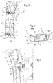
- la
figure 1 est une vue en perspective d'un montant de caisse sous pavillon, équipé d'une goulotte conforme à l'invention. - la
figure 2 est une vue analogue à lafigure 1 , goulotte retirée. - la
figure 3 est une vue montrant l'intérieur de la goulotte de l'invention avec le câblage et les agrafes de câblage. - la
figure 4 est une vue en section A-A de lafigure 3 . - la
figure 5 est une vue du montant et de la goulotte, en coupe verticale passant par le milieu d'une agrafe de câblage.
- the
figure 1 is a perspective view of a flag body amount, equipped with a chute according to the invention. - the
figure 2 is a view similar to thefigure 1 , chute removed. - the
figure 3 is a view showing the interior of the chute of the invention with the wiring and the wiring clips. - the
figure 4 is a view in section AA of thefigure 3 . - the
figure 5 is a view of the upright and the chute, in vertical section passing through the middle of a wiring clip.
Les figures montrent un montant 1 vertical ou oblique de caisse, tel qu'un pied milieu de caisse ou un montant de baie, constitué par un profilé de tôle. Le montant 1 relie une partie basse de caisse au pavillon, lequel est recouvert d'une garniture de pavillon 2.The figures show a vertical upright 1 or oblique body, such as a central pillar or an amount of bay, consisting of a sheet metal profile. The
Sur une paroi du profilé métallique formant le montant 1, éventuellement conformée en gorge 3, on peut venir maintenir et/ou guider un câblage 4 par des agrafes de câblage 5 qui ont été préalablement fixées dans des trous prévus sur la paroi du profilé. À cet effet, les agrafes comportent d'une part des moyens d'ancrage dans le montant, d'autre part des moyens de réception et de maintien ou de guidage de câblage, et enfin des moyens de clipsage d'une goulotte.On a wall of the metal profile forming the upright 1, possibly shaped as a
Chaque agrafe 5 se présente sensiblement sous la forme d'une pince élastique en C munie d'un pied 6 de fixation encliquetable (par clipsage) dans un trou de la paroi du profilé 1. Le pied 6, par exemple cylindrique à profil en « dents de sapin », constitue un moyen d'ancrage rapide de l'agrafe dans la paroi du montant profilé 1, qui place l'agrafe dans une position fixe et déterminée. La pince en C comporte deux branches élastiques 7, 7' entre lesquelles le câblage 4 peut être introduit et se trouve retenu et/ou guidé grâce à la forme en crochet desdites branches, retournées vers l'intérieur de la pince. Les branches 7, 7' constituent les moyens de réception et de maintien ou de guidage du câblage. L'agrafe 5 comporte aussi, de part et d'autre des branches 7, 7', deux ailes 8 et 9 destinées à recevoir des éléments d'accrochage de la goulotte 10 de câblage, destinée à venir se fixer au-dessus du câblage 4 pour le protéger et cacher comme montré à la
La goulotte 10 a une forme de canal en C, avec un fond 11 et deux ailes 12, lesquelles viennent sensiblement en appui sur la paroi du profilé 1 quand la goulotte 10 est fixée. Pour sa fixation, la goulotte 10 comporte de place en place des profils moulés 13 et 14 dont la forme est destinée à coopérer avec les agrafes 5 pour permettre le clipsage de la goulotte 10 sur lesdites agrafes. Le profil de clipsage 13 part du fond 11 et se termine par un crochet 16 qui vient s'accrocher sur un crochet complémentaire formé sur la partie extérieure de la branche 7'. Le profil 14 prend naissance sur le fond 11 et l'aile 12 et comporte un crochet 17 qui vient s'engager dans une fente formée dans l'aile 8, laquelle comporte vers l'extérieur une rampe permettant, lors de la mise en place de la goulotte 10, au crochet 17 de glisser sur cette rampe et de faire pivoter élastiquement l'aile 8 vers l'intérieur de l'agrafe, jusqu'au moment où le crochet 17 peut pénétrer dans ladite fente.The
Les éléments qui viennent d'être décrits permettent de clipser la goulotte 10 sur le montant de caisse 1 et de la maintenir dans une certaine position, mais n'assurent pas exactement son positionnement vertical, d'où il peut résulter un jeu visible initial entre le haut de la goulotte 10 et la garniture de pavillon 2. De plus, même en l'absence de jeu initial si la goulotte a été soigneusement positionnée, les vibrations du véhicule en fonctionnement peuvent entraîner un déplacement de la goulotte dans sa direction longitudinale et faire apparaître un jeu. Afin de garantir un positionnement vertical exact et une absence de jeu, aussi bien au montage qu'en cours d'utilisation du véhicule, il est prévu selon l'invention un appui vertical de la goulotte sur un élément de référence du montage, et en pratique, il est prévu d'ajouter dans la goulotte verticale une nervure horizontale 30, par exemple formée par moulage au niveau du profil de clipsage 14, cette nervure 30 venant s'appuyer sur la surface horizontale supérieure 21 d'une des agrafes 5 choisie pour référence. Comme on le voit, la nervure 30 est formée en équerre entre le fond 11 et l'aile 12 de la goulotte, ces deux liaisons lui donnant une grande stabilité. De la sorte, la position verticale de la goulotte 10 se trouve fixée avec précision par rapport à la surface de référence 21 choisie, en l'occurrence le haut d'une agrafe 5 (une seule des plusieurs agrafes de câblage), et on peut donc faire en sorte que le clipsage de la goulotte 10 place celle-ci sans jeu par rapport à la garniture de pavillon 2. Ainsi, la nervure d'appui 30 fixe la position de départ de la goulotte 10 sur le montant 1 et la maintient en cours d'utilisation du véhicule.The elements that have just been described make it possible to clip the
Claims (7)
- Device for assembling cable trunking (10) on a motor vehicle body component (1), characterized in that it comprises:- a body component (1),- at least one cable clip (5) which comprises, on the one hand, means (7, 7') for retaining a cable (4) in a guided manner and, on the other hand, means (8, 9) for clip-fitting the trunking,- at least one transverse support surface (21) which is positioned and fixed, directly or indirectly, on the body component in order to form a topological reference location,characterized in that the trunking (10) comprises complementary clip-fitting means (13, 16, 14, 17) which cooperate with the means (8, 9) of the clips (s) (5) in order to allow the trunking (10) to be clip-fitted to the clip (s) (4), this clip-fitting fixing the position of the trunking (10) in directions transverse to the trunking, the trunking (10) further comprising a transverse support relief (30) which, during the clip-fitting operation, is supported on the transverse support surface (21) in order to block the trunking (10) in a longitudinal direction of the trunking when it is clip-fitted.
- Device according to Claim 1, characterized in that the support relief (30) is a transverse rib which is provided in the trunking (10).
- Device according to Claim 1 or Claim 2, characterized in that the transverse support surface (21) is constituted by a reference surface of a cable clip (5).
- Device according to Claim 3, characterized in that the reference surface of the clip (5) is formed by an upper portion (21) of the clip (5).
- Device according to any one of Claims 1 to 4, characterized in that the clips (5) comprise, on the one hand, means (6) for anchoring in the body component (1) and, on the other hand, means (7, 7') for receiving and retaining or guiding the cable, and finally means (8, 9) for clip-fitting a trunking.
- Device according to Claim 5, characterized in that the means (6) for anchoring the clip (5) in the body component (1) are constituted by a snap-fitting foot.
- Device according to any one of the preceding claims, characterized in that the body component (1) is a bodywork pillar, in particular a B-pillar or a windscreen pillar.
Applications Claiming Priority (2)
| Application Number | Priority Date | Filing Date | Title |
|---|---|---|---|
| FR1258988A FR2995965B1 (en) | 2012-09-25 | 2012-09-25 | DEVICE FOR MOUNTING A WIRING CHUTE ON A CAR BODY COMPONENT |
| PCT/FR2013/052163 WO2014049236A1 (en) | 2012-09-25 | 2013-09-19 | Device for installing cable trunking on a motor vehicle body part |
Publications (2)
| Publication Number | Publication Date |
|---|---|
| EP2900521A1 EP2900521A1 (en) | 2015-08-05 |
| EP2900521B1 true EP2900521B1 (en) | 2017-04-05 |
Family
ID=47178194
Family Applications (1)
| Application Number | Title | Priority Date | Filing Date |
|---|---|---|---|
| EP13774761.4A Not-in-force EP2900521B1 (en) | 2012-09-25 | 2013-09-19 | Device for installing cable trunking on a motor vehicle body part |
Country Status (5)
| Country | Link |
|---|---|
| US (1) | US9789829B2 (en) |
| EP (1) | EP2900521B1 (en) |
| CN (1) | CN104755326B (en) |
| FR (1) | FR2995965B1 (en) |
| WO (1) | WO2014049236A1 (en) |
Families Citing this family (4)
| Publication number | Priority date | Publication date | Assignee | Title |
|---|---|---|---|---|
| US10029625B1 (en) * | 2017-06-22 | 2018-07-24 | GM Global Technology Operations LLC | Bracket support structures for vehicle trim panels, and methods of using the same |
| JP7040378B2 (en) * | 2018-09-20 | 2022-03-23 | トヨタ自動車株式会社 | Vehicle roof structure |
| FR3095843B1 (en) | 2019-05-07 | 2021-07-16 | Psa Automobiles Sa | SET-UP FIXING CLIP AND CHUTE EQUIPPED WITH THE SAID CLIP |
| FR3138379B1 (en) | 2022-07-29 | 2024-06-14 | Psa Automobiles Sa | WIRING TUNING FOR PRE-FIXING AN AUTOMOTIVE BATTERY |
Family Cites Families (12)
| Publication number | Priority date | Publication date | Assignee | Title |
|---|---|---|---|---|
| DE4424288A1 (en) * | 1994-07-09 | 1996-01-11 | Opel Adam Ag | Motor vehicle |
| US5806812A (en) * | 1996-12-12 | 1998-09-15 | Ut Automotive Dearborn, Inc. | Adjustable attachment unit |
| US5962814A (en) * | 1997-10-14 | 1999-10-05 | Yazaki Corporation | Wire harness trough with pivoting guide |
| JP4044406B2 (en) * | 2002-09-30 | 2008-02-06 | ポップリベット・ファスナー株式会社 | Floor carpet and wire harness fasteners |
| JP4566863B2 (en) * | 2005-08-31 | 2010-10-20 | 本田技研工業株式会社 | Cable holding device for vehicle |
| JP4373969B2 (en) * | 2005-09-22 | 2009-11-25 | 株式会社パイオラックス | Harness clip |
| JP5272510B2 (en) * | 2008-05-13 | 2013-08-28 | 株式会社オートネットワーク技術研究所 | Wire harness with protective material for vehicle and wiring structure of wire harness for vehicle |
| DE102009002197A1 (en) * | 2009-04-06 | 2010-10-14 | Robert Bosch Gmbh | Fastening device for a cable |
| JP2011230593A (en) * | 2010-04-26 | 2011-11-17 | Toyota Motor Corp | Carpet clamp |
| FR2964712B1 (en) * | 2010-09-09 | 2013-11-01 | Raymond A & Cie | DEVICE FOR FIXING AT LEAST ONE ELONGATED MEMBER ON A SUPPORT |
| US8366059B2 (en) * | 2011-01-06 | 2013-02-05 | GM Global Technology Operations LLC | Position controlled cable guide clip |
| WO2013051090A1 (en) * | 2011-10-03 | 2013-04-11 | トヨタ車体 株式会社 | Clamp member |
-
2012
- 2012-09-25 FR FR1258988A patent/FR2995965B1/en active Active
-
2013
- 2013-09-19 CN CN201380055422.2A patent/CN104755326B/en not_active Expired - Fee Related
- 2013-09-19 US US14/431,087 patent/US9789829B2/en not_active Expired - Fee Related
- 2013-09-19 WO PCT/FR2013/052163 patent/WO2014049236A1/en not_active Ceased
- 2013-09-19 EP EP13774761.4A patent/EP2900521B1/en not_active Not-in-force
Also Published As
| Publication number | Publication date |
|---|---|
| FR2995965A1 (en) | 2014-03-28 |
| US9789829B2 (en) | 2017-10-17 |
| WO2014049236A1 (en) | 2014-04-03 |
| FR2995965B1 (en) | 2014-08-29 |
| CN104755326A (en) | 2015-07-01 |
| US20150274094A1 (en) | 2015-10-01 |
| EP2900521A1 (en) | 2015-08-05 |
| CN104755326B (en) | 2017-05-03 |
Similar Documents
| Publication | Publication Date | Title |
|---|---|---|
| EP2900521B1 (en) | Device for installing cable trunking on a motor vehicle body part | |
| EP0983891A1 (en) | Guiding groove for a motor vehicle and its method for positioning, especially by differential bending | |
| FR2914595A3 (en) | Passenger compartment's element i.e. boot, storing system for motor vehicle, has fixation unit with removable element that is selectively received by rail, where element is displaced in sliding, is locked and is carried by hooking element | |
| EP2585342B1 (en) | Intermediate attachment part for vehicle trimming | |
| FR2716653A1 (en) | Vehicle headlamp assembly. | |
| EP3233584B1 (en) | Transversely reinforced fixation of a safety belt retractor on the b-pillar of a vehicle | |
| WO2015104467A1 (en) | Vehicle provided with a shock-absorbing element | |
| EP0569297A1 (en) | Holding device for several conduits, cables or the like | |
| EP3849845B1 (en) | Device for attaching a trim to a motor vehicle bodywork structure such as a window post | |
| EP2154024B1 (en) | Indexing system of an automotive lighting element | |
| EP3601016B1 (en) | Vehicle body trim part | |
| EP3124328B1 (en) | Roof bar | |
| EP1254038B1 (en) | Internal arrangement for a motor vehicle passenger compartment | |
| EP2558664B1 (en) | Adjustment process of the position of a lock assembly for an openable body section of a vehicle | |
| EP3390161B1 (en) | Device for attaching a covering element to a window post structure | |
| FR2944738A1 (en) | AUTOMOTIVE VEHICLE DOOR COMPRISING MEANS FOR ATTACHING A TRIM PANEL AND A SUPPORT FOR ATTACHING A DOOR OPENING CONTROL TO THE DOOR. | |
| EP3831629A1 (en) | Bi-injected sealing device with hook | |
| EP1394918A1 (en) | Device for fixing a conduit under a ceiling cable channel comprising use of same | |
| FR2942603A1 (en) | Inner liner for center pillar of body of motor vehicle, has curtain-forming plate whose edge comprises protuberance constituting blocking unit that blocks plate with respect to guides to prevent ejection of plate to outer side of opening | |
| EP3887207A1 (en) | Support for a motor vehicle cabin wiring harness | |
| FR3026061A1 (en) | SYSTEM FOR FASTENING A TANK ON THE SIDE PARTS OF A MOTOR VEHICLE TIP | |
| FR2926342A1 (en) | Blind fixation device for e.g. lateral finishing part of cowl vent grille in motor vehicle, has locking element engaged through orifice of support part to block finishing part at support part through exertion of maintaining force on hook | |
| EP1520999A2 (en) | Arragement for mounting a trim elelment | |
| FR2749889A1 (en) | SUN VISOR SUPPORT HOOK | |
| FR3084306A1 (en) | VEHICLE COMPRISING A LIGHTING PART WITH SIMPLIFIED FIXING |
Legal Events
| Date | Code | Title | Description |
|---|---|---|---|
| PUAI | Public reference made under article 153(3) epc to a published international application that has entered the european phase |
Free format text: ORIGINAL CODE: 0009012 |
|
| 17P | Request for examination filed |
Effective date: 20150319 |
|
| AK | Designated contracting states |
Kind code of ref document: A1 Designated state(s): AL AT BE BG CH CY CZ DE DK EE ES FI FR GB GR HR HU IE IS IT LI LT LU LV MC MK MT NL NO PL PT RO RS SE SI SK SM TR |
|
| AX | Request for extension of the european patent |
Extension state: BA ME |
|
| DAX | Request for extension of the european patent (deleted) | ||
| REG | Reference to a national code |
Ref country code: DE Ref legal event code: R079 Ref document number: 602013019510 Country of ref document: DE Free format text: PREVIOUS MAIN CLASS: B60R0016020000 Ipc: F16L0003240000 |
|
| RIC1 | Information provided on ipc code assigned before grant |
Ipc: F16L 3/13 20060101ALI20160502BHEP Ipc: B60R 16/02 20060101ALI20160502BHEP Ipc: F16L 3/24 20060101AFI20160502BHEP |
|
| GRAP | Despatch of communication of intention to grant a patent |
Free format text: ORIGINAL CODE: EPIDOSNIGR1 |
|
| INTG | Intention to grant announced |
Effective date: 20161012 |
|
| GRAS | Grant fee paid |
Free format text: ORIGINAL CODE: EPIDOSNIGR3 |
|
| GRAA | (expected) grant |
Free format text: ORIGINAL CODE: 0009210 |
|
| AK | Designated contracting states |
Kind code of ref document: B1 Designated state(s): AL AT BE BG CH CY CZ DE DK EE ES FI FR GB GR HR HU IE IS IT LI LT LU LV MC MK MT NL NO PL PT RO RS SE SI SK SM TR |
|
| REG | Reference to a national code |
Ref country code: GB Ref legal event code: FG4D Free format text: NOT ENGLISH |
|
| REG | Reference to a national code |
Ref country code: CH Ref legal event code: EP |
|
| REG | Reference to a national code |
Ref country code: AT Ref legal event code: REF Ref document number: 882155 Country of ref document: AT Kind code of ref document: T Effective date: 20170415 |
|
| REG | Reference to a national code |
Ref country code: IE Ref legal event code: FG4D Free format text: LANGUAGE OF EP DOCUMENT: FRENCH |
|
| REG | Reference to a national code |
Ref country code: DE Ref legal event code: R096 Ref document number: 602013019510 Country of ref document: DE |
|
| REG | Reference to a national code |
Ref country code: NL Ref legal event code: MP Effective date: 20170405 |
|
| REG | Reference to a national code |
Ref country code: LT Ref legal event code: MG4D |
|
| REG | Reference to a national code |
Ref country code: AT Ref legal event code: MK05 Ref document number: 882155 Country of ref document: AT Kind code of ref document: T Effective date: 20170405 |
|
| REG | Reference to a national code |
Ref country code: FR Ref legal event code: PLFP Year of fee payment: 5 |
|
| PG25 | Lapsed in a contracting state [announced via postgrant information from national office to epo] |
Ref country code: NL Free format text: LAPSE BECAUSE OF FAILURE TO SUBMIT A TRANSLATION OF THE DESCRIPTION OR TO PAY THE FEE WITHIN THE PRESCRIBED TIME-LIMIT Effective date: 20170405 |
|
| PG25 | Lapsed in a contracting state [announced via postgrant information from national office to epo] |
Ref country code: GR Free format text: LAPSE BECAUSE OF FAILURE TO SUBMIT A TRANSLATION OF THE DESCRIPTION OR TO PAY THE FEE WITHIN THE PRESCRIBED TIME-LIMIT Effective date: 20170706 Ref country code: ES Free format text: LAPSE BECAUSE OF FAILURE TO SUBMIT A TRANSLATION OF THE DESCRIPTION OR TO PAY THE FEE WITHIN THE PRESCRIBED TIME-LIMIT Effective date: 20170405 Ref country code: AT Free format text: LAPSE BECAUSE OF FAILURE TO SUBMIT A TRANSLATION OF THE DESCRIPTION OR TO PAY THE FEE WITHIN THE PRESCRIBED TIME-LIMIT Effective date: 20170405 Ref country code: HR Free format text: LAPSE BECAUSE OF FAILURE TO SUBMIT A TRANSLATION OF THE DESCRIPTION OR TO PAY THE FEE WITHIN THE PRESCRIBED TIME-LIMIT Effective date: 20170405 Ref country code: FI Free format text: LAPSE BECAUSE OF FAILURE TO SUBMIT A TRANSLATION OF THE DESCRIPTION OR TO PAY THE FEE WITHIN THE PRESCRIBED TIME-LIMIT Effective date: 20170405 Ref country code: NO Free format text: LAPSE BECAUSE OF FAILURE TO SUBMIT A TRANSLATION OF THE DESCRIPTION OR TO PAY THE FEE WITHIN THE PRESCRIBED TIME-LIMIT Effective date: 20170705 Ref country code: LT Free format text: LAPSE BECAUSE OF FAILURE TO SUBMIT A TRANSLATION OF THE DESCRIPTION OR TO PAY THE FEE WITHIN THE PRESCRIBED TIME-LIMIT Effective date: 20170405 |
|
| PG25 | Lapsed in a contracting state [announced via postgrant information from national office to epo] |
Ref country code: RS Free format text: LAPSE BECAUSE OF FAILURE TO SUBMIT A TRANSLATION OF THE DESCRIPTION OR TO PAY THE FEE WITHIN THE PRESCRIBED TIME-LIMIT Effective date: 20170405 Ref country code: BG Free format text: LAPSE BECAUSE OF FAILURE TO SUBMIT A TRANSLATION OF THE DESCRIPTION OR TO PAY THE FEE WITHIN THE PRESCRIBED TIME-LIMIT Effective date: 20170705 Ref country code: LV Free format text: LAPSE BECAUSE OF FAILURE TO SUBMIT A TRANSLATION OF THE DESCRIPTION OR TO PAY THE FEE WITHIN THE PRESCRIBED TIME-LIMIT Effective date: 20170405 Ref country code: SE Free format text: LAPSE BECAUSE OF FAILURE TO SUBMIT A TRANSLATION OF THE DESCRIPTION OR TO PAY THE FEE WITHIN THE PRESCRIBED TIME-LIMIT Effective date: 20170405 Ref country code: IS Free format text: LAPSE BECAUSE OF FAILURE TO SUBMIT A TRANSLATION OF THE DESCRIPTION OR TO PAY THE FEE WITHIN THE PRESCRIBED TIME-LIMIT Effective date: 20170805 Ref country code: PL Free format text: LAPSE BECAUSE OF FAILURE TO SUBMIT A TRANSLATION OF THE DESCRIPTION OR TO PAY THE FEE WITHIN THE PRESCRIBED TIME-LIMIT Effective date: 20170405 |
|
| REG | Reference to a national code |
Ref country code: DE Ref legal event code: R097 Ref document number: 602013019510 Country of ref document: DE |
|
| PG25 | Lapsed in a contracting state [announced via postgrant information from national office to epo] |
Ref country code: SK Free format text: LAPSE BECAUSE OF FAILURE TO SUBMIT A TRANSLATION OF THE DESCRIPTION OR TO PAY THE FEE WITHIN THE PRESCRIBED TIME-LIMIT Effective date: 20170405 Ref country code: EE Free format text: LAPSE BECAUSE OF FAILURE TO SUBMIT A TRANSLATION OF THE DESCRIPTION OR TO PAY THE FEE WITHIN THE PRESCRIBED TIME-LIMIT Effective date: 20170405 Ref country code: CZ Free format text: LAPSE BECAUSE OF FAILURE TO SUBMIT A TRANSLATION OF THE DESCRIPTION OR TO PAY THE FEE WITHIN THE PRESCRIBED TIME-LIMIT Effective date: 20170405 Ref country code: DK Free format text: LAPSE BECAUSE OF FAILURE TO SUBMIT A TRANSLATION OF THE DESCRIPTION OR TO PAY THE FEE WITHIN THE PRESCRIBED TIME-LIMIT Effective date: 20170405 Ref country code: RO Free format text: LAPSE BECAUSE OF FAILURE TO SUBMIT A TRANSLATION OF THE DESCRIPTION OR TO PAY THE FEE WITHIN THE PRESCRIBED TIME-LIMIT Effective date: 20170405 |
|
| PLBE | No opposition filed within time limit |
Free format text: ORIGINAL CODE: 0009261 |
|
| STAA | Information on the status of an ep patent application or granted ep patent |
Free format text: STATUS: NO OPPOSITION FILED WITHIN TIME LIMIT |
|
| PG25 | Lapsed in a contracting state [announced via postgrant information from national office to epo] |
Ref country code: SM Free format text: LAPSE BECAUSE OF FAILURE TO SUBMIT A TRANSLATION OF THE DESCRIPTION OR TO PAY THE FEE WITHIN THE PRESCRIBED TIME-LIMIT Effective date: 20170405 Ref country code: IT Free format text: LAPSE BECAUSE OF FAILURE TO SUBMIT A TRANSLATION OF THE DESCRIPTION OR TO PAY THE FEE WITHIN THE PRESCRIBED TIME-LIMIT Effective date: 20170405 |
|
| 26N | No opposition filed |
Effective date: 20180108 |
|
| REG | Reference to a national code |
Ref country code: CH Ref legal event code: PL |
|
| PG25 | Lapsed in a contracting state [announced via postgrant information from national office to epo] |
Ref country code: SI Free format text: LAPSE BECAUSE OF FAILURE TO SUBMIT A TRANSLATION OF THE DESCRIPTION OR TO PAY THE FEE WITHIN THE PRESCRIBED TIME-LIMIT Effective date: 20170405 Ref country code: MC Free format text: LAPSE BECAUSE OF FAILURE TO SUBMIT A TRANSLATION OF THE DESCRIPTION OR TO PAY THE FEE WITHIN THE PRESCRIBED TIME-LIMIT Effective date: 20170405 |
|
| REG | Reference to a national code |
Ref country code: IE Ref legal event code: MM4A |
|
| REG | Reference to a national code |
Ref country code: BE Ref legal event code: MM Effective date: 20170930 |
|
| PG25 | Lapsed in a contracting state [announced via postgrant information from national office to epo] |
Ref country code: LU Free format text: LAPSE BECAUSE OF NON-PAYMENT OF DUE FEES Effective date: 20170919 |
|
| PG25 | Lapsed in a contracting state [announced via postgrant information from national office to epo] |
Ref country code: IE Free format text: LAPSE BECAUSE OF NON-PAYMENT OF DUE FEES Effective date: 20170919 Ref country code: CH Free format text: LAPSE BECAUSE OF NON-PAYMENT OF DUE FEES Effective date: 20170930 Ref country code: LI Free format text: LAPSE BECAUSE OF NON-PAYMENT OF DUE FEES Effective date: 20170930 |
|
| PG25 | Lapsed in a contracting state [announced via postgrant information from national office to epo] |
Ref country code: BE Free format text: LAPSE BECAUSE OF NON-PAYMENT OF DUE FEES Effective date: 20170930 |
|
| REG | Reference to a national code |
Ref country code: FR Ref legal event code: PLFP Year of fee payment: 6 |
|
| PG25 | Lapsed in a contracting state [announced via postgrant information from national office to epo] |
Ref country code: MT Free format text: LAPSE BECAUSE OF FAILURE TO SUBMIT A TRANSLATION OF THE DESCRIPTION OR TO PAY THE FEE WITHIN THE PRESCRIBED TIME-LIMIT Effective date: 20170405 |
|
| PG25 | Lapsed in a contracting state [announced via postgrant information from national office to epo] |
Ref country code: HU Free format text: LAPSE BECAUSE OF FAILURE TO SUBMIT A TRANSLATION OF THE DESCRIPTION OR TO PAY THE FEE WITHIN THE PRESCRIBED TIME-LIMIT; INVALID AB INITIO Effective date: 20130919 |
|
| PG25 | Lapsed in a contracting state [announced via postgrant information from national office to epo] |
Ref country code: CY Free format text: LAPSE BECAUSE OF FAILURE TO SUBMIT A TRANSLATION OF THE DESCRIPTION OR TO PAY THE FEE WITHIN THE PRESCRIBED TIME-LIMIT Effective date: 20170405 |
|
| PG25 | Lapsed in a contracting state [announced via postgrant information from national office to epo] |
Ref country code: MK Free format text: LAPSE BECAUSE OF FAILURE TO SUBMIT A TRANSLATION OF THE DESCRIPTION OR TO PAY THE FEE WITHIN THE PRESCRIBED TIME-LIMIT Effective date: 20170405 |
|
| PG25 | Lapsed in a contracting state [announced via postgrant information from national office to epo] |
Ref country code: TR Free format text: LAPSE BECAUSE OF FAILURE TO SUBMIT A TRANSLATION OF THE DESCRIPTION OR TO PAY THE FEE WITHIN THE PRESCRIBED TIME-LIMIT Effective date: 20170405 |
|
| PG25 | Lapsed in a contracting state [announced via postgrant information from national office to epo] |
Ref country code: PT Free format text: LAPSE BECAUSE OF FAILURE TO SUBMIT A TRANSLATION OF THE DESCRIPTION OR TO PAY THE FEE WITHIN THE PRESCRIBED TIME-LIMIT Effective date: 20170405 |
|
| PG25 | Lapsed in a contracting state [announced via postgrant information from national office to epo] |
Ref country code: AL Free format text: LAPSE BECAUSE OF FAILURE TO SUBMIT A TRANSLATION OF THE DESCRIPTION OR TO PAY THE FEE WITHIN THE PRESCRIBED TIME-LIMIT Effective date: 20170405 |
|
| PGFP | Annual fee paid to national office [announced via postgrant information from national office to epo] |
Ref country code: GB Payment date: 20220920 Year of fee payment: 10 Ref country code: DE Payment date: 20220920 Year of fee payment: 10 |
|
| PGFP | Annual fee paid to national office [announced via postgrant information from national office to epo] |
Ref country code: FR Payment date: 20220922 Year of fee payment: 10 |
|
| P01 | Opt-out of the competence of the unified patent court (upc) registered |
Effective date: 20230608 |
|
| REG | Reference to a national code |
Ref country code: DE Ref legal event code: R119 Ref document number: 602013019510 Country of ref document: DE |
|
| GBPC | Gb: european patent ceased through non-payment of renewal fee |
Effective date: 20230919 |
|
| PG25 | Lapsed in a contracting state [announced via postgrant information from national office to epo] |
Ref country code: GB Free format text: LAPSE BECAUSE OF NON-PAYMENT OF DUE FEES Effective date: 20230919 |
|
| PG25 | Lapsed in a contracting state [announced via postgrant information from national office to epo] |
Ref country code: GB Free format text: LAPSE BECAUSE OF NON-PAYMENT OF DUE FEES Effective date: 20230919 Ref country code: FR Free format text: LAPSE BECAUSE OF NON-PAYMENT OF DUE FEES Effective date: 20230930 Ref country code: DE Free format text: LAPSE BECAUSE OF NON-PAYMENT OF DUE FEES Effective date: 20240403 |