EP2900974B1 - Durchflussmodifikator für eine brennstoffdüsenspitze einer brennkammer - Google Patents
Durchflussmodifikator für eine brennstoffdüsenspitze einer brennkammer Download PDFInfo
- Publication number
- EP2900974B1 EP2900974B1 EP13842187.0A EP13842187A EP2900974B1 EP 2900974 B1 EP2900974 B1 EP 2900974B1 EP 13842187 A EP13842187 A EP 13842187A EP 2900974 B1 EP2900974 B1 EP 2900974B1
- Authority
- EP
- European Patent Office
- Prior art keywords
- fuel
- along
- assembly
- swirl plug
- path
- Prior art date
- Legal status (The legal status is an assumption and is not a legal conclusion. Google has not performed a legal analysis and makes no representation as to the accuracy of the status listed.)
- Active
Links
Images


Classifications
-
- F—MECHANICAL ENGINEERING; LIGHTING; HEATING; WEAPONS; BLASTING
- F23—COMBUSTION APPARATUS; COMBUSTION PROCESSES
- F23D—BURNERS
- F23D11/00—Burners using a direct spraying action of liquid droplets or vaporised liquid into the combustion space
- F23D11/36—Details
- F23D11/38—Nozzles; Cleaning devices therefor
- F23D11/383—Nozzles; Cleaning devices therefor with swirl means
-
- F—MECHANICAL ENGINEERING; LIGHTING; HEATING; WEAPONS; BLASTING
- F23—COMBUSTION APPARATUS; COMBUSTION PROCESSES
- F23D—BURNERS
- F23D11/00—Burners using a direct spraying action of liquid droplets or vaporised liquid into the combustion space
- F23D11/10—Burners using a direct spraying action of liquid droplets or vaporised liquid into the combustion space the spraying being induced by a gaseous medium, e.g. water vapour
- F23D11/106—Burners using a direct spraying action of liquid droplets or vaporised liquid into the combustion space the spraying being induced by a gaseous medium, e.g. water vapour medium and fuel meeting at the burner outlet
- F23D11/107—Burners using a direct spraying action of liquid droplets or vaporised liquid into the combustion space the spraying being induced by a gaseous medium, e.g. water vapour medium and fuel meeting at the burner outlet at least one of both being subjected to a swirling motion
-
- F—MECHANICAL ENGINEERING; LIGHTING; HEATING; WEAPONS; BLASTING
- F23—COMBUSTION APPARATUS; COMBUSTION PROCESSES
- F23R—GENERATING COMBUSTION PRODUCTS OF HIGH PRESSURE OR HIGH VELOCITY, e.g. GAS-TURBINE COMBUSTION CHAMBERS
- F23R3/00—Continuous combustion chambers using liquid or gaseous fuel
- F23R3/28—Continuous combustion chambers using liquid or gaseous fuel characterised by the fuel supply
-
- F—MECHANICAL ENGINEERING; LIGHTING; HEATING; WEAPONS; BLASTING
- F23—COMBUSTION APPARATUS; COMBUSTION PROCESSES
- F23D—BURNERS
- F23D2900/00—Special features of, or arrangements for burners using fluid fuels or solid fuels suspended in a carrier gas
- F23D2900/00016—Preventing or reducing deposit build-up on burner parts, e.g. from carbon
-
- F—MECHANICAL ENGINEERING; LIGHTING; HEATING; WEAPONS; BLASTING
- F23—COMBUSTION APPARATUS; COMBUSTION PROCESSES
- F23R—GENERATING COMBUSTION PRODUCTS OF HIGH PRESSURE OR HIGH VELOCITY, e.g. GAS-TURBINE COMBUSTION CHAMBERS
- F23R2900/00—Special features of, or arrangements for continuous combustion chambers; Combustion processes therefor
- F23R2900/00004—Preventing formation of deposits on surfaces of gas turbine components, e.g. coke deposits
Definitions
- the present invention relates to a fuel injector nozzle assembly, to a combustor assembly for a gas turbine, and to a method for injecting fuel into a gas turbine engine combustor.
- Gas turbine engines include a combustor for generating combustion products to help power the engine.
- compressed air is provided to the combustor and is mixed with fuel injected into a combustion chamber.
- the fuel/air mixture is ignited to provide combustion.
- the combustion products then exit the combustor and pass through a turbine section that extracts rotational energy from the combustion products.
- Document FR 2 817 017 A1 discloses a fuel injector nozzle assembly having radial fuel jets, the fuel injector nozzle assembly comprising a body extending along an axis, wherein a fuel flow path is configured to flow fuel close to the axis before turning radially outward, and fuel outlet passages extending through the body at angles relative to the axis to permit fuel injection of the fuel passing through the fuel flow path in general radial directions, thereby providing a radial fuel jet injection pattern in a combustion chamber, a core swirl plug positioned at least partially within the body, the core swirl plug having a flow modifying structure configured to swirl fuel passing along the fuel flow path prior to reaching a fuel outlet passage at a location upstream from a distal end of the nozzle assembly where the fuel exits the nozzle via the fuel outlet passage for combustion, and a support having a support body and a tube configured to carry fuel, wherein the support body abuts the body, and a heat shield sleeve positioned between the body and the core
- Fuel nozzles deliver fuel in particular patterns to help facilitate combustion. Parameters such as swirl, velocity, and pressure are tightly controlled by the fuel nozzle to help promote desired performance. During operation, fuel nozzles that inject fuel in the combustor are subjected to extreme thermal conditions as well as various other forces. Balancing these concerns in a working fuel nozzle can be difficult.
- a fuel injector nozzle assembly includes a body extending along an axis and a core swirl plug positioned at least partially within the body.
- the core swirl plug has a flow modifying structure configured to swirl fuel at a location upstream from a distal end of the nozzle assembly, a support having a support body and a tube configured to carry fuel, wherein the support body abuts the body, and a heat shield sleeve positioned between the body and the core swirl plug, wherein the core swirl plug and the body are spaced from each other.
- FIG. 1 is a cross-sectional view of an embodiment of a gas turbine engine combustor section 20 having a generally annular combustion chamber 22. For simplicity, cross hatching is omitted and only an upper half of the combustor section above an engine centerline axis C L is shown in FIG. 1 .
- the combustion chamber 22 in the illustrated embodiment is bounded by a bulkhead 24, inner wall 26 and outer wall 28 extending from the bulkhead 24 to an outlet 30 located upstream of a turbine section (not shown).
- the bulkhead 24 and the walls 26 and 28 can be of double layer construction with an outer shell and an inner panel array.
- the bulkhead 24 and the walls 26 and 28 can each include suitable thermal barrier coatings and/or cooling fluid openings.
- One or more swirlers 32 can be mounted to the bulkhead 24 that provide one or more corresponding upstream fluid inlets to the combustion chamber 22, for instance, using compressed air from a compressor section (not shown).
- the swirlers 32 can be angularly spaced about the engine centerline in any desired pattern, in desired radial positions.
- a fuel nozzle 40 can be associated with each swirler 32. Different fuel nozzles 40 can have different configurations, as desired for particular applications, or can have a substantially identical configuration. For instance, any given nozzle 40 can have a simplex, duplex or other configuration, as explained further below.
- the fuel nozzle 40 has an outboard flange 42 secured to an engine case 44.
- a support (or leg) 46 extends generally radially from the flange 42, and can include suitable internal passageways for fluid (e.g., fuel) transport.
- a nozzle tip 48 can be supported at a distal end of the nozzle 40. The nozzle tip 48 can extend into the associated swirler 32 and can have outlets for introducing fuel (e.g., liquid jet fuel) to air flowing through the swirler 32.
- One or more igniters 50 can be mounted to the case 44 and can have tip portions 52 extending into the combustion chamber 22 for igniting a fuel/air mixture passing downstream from the swirlers 32 and the fuel nozzles 40.
- duplex, simplex or other types of fuel nozzles can be interspersed at different locations around the combustor section 20, as desired.
- Duplex fuel nozzles provide two fuel delivery paths to the combustion chamber 22 while simplex fuel nozzles provide one fuel delivery path to the combustion chamber 22. It is possible to provide fuel nozzles with nearly any number of desired fuel delivery paths, such as having three or more paths. Separate fuel delivery paths can allow separate and independent control of fuel flow through each path, and/or other benefits. For example, one fuel path can be used to provide a pilot while one or more additional fuel paths selectively provide fuel for other operating modes. Alternatively, all of the nozzles 40 in the combustor section 20 can be of the same configuration (e.g., simplex, duplex, etc.).
- hot air flow is present at or near the swirlers 32 and at least portions of the nozzles 40 (e.g., the support 46 and/or nozzle tip 48).
- the nozzles 40 can use fuel passing through the nozzle tips 48 as a heat sink to help cool the nozzles 40, as explained further below.
- the embodiment of the combustor section 20 shown in FIG. 1 is presented by way of example only, and not limitation. Various other combustor configurations are possible. For instance, a can combustor configuration is possible in alternative embodiments. Moreover, although the combustor section 20 is usable with a gas turbine engine, explanation of operation of the engine as a whole is unnecessary here because gas turbine engines are well known.
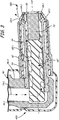
- FIG. 2 is a cross-sectional view of an embodiment of a duplex fuel nozzle 40D and fuel nozzle tip 48D.
- the nozzle tip 48D includes a heat shield 60, an outer sleeve 62, a body 64, a heat shield sleeve 66, a core swirl plug 68, an inner body 70, and a swirl plug 72.
- the support 46 includes concentric tubes 46-1 and 46-2 and a body 46-3. Arrows are shown in FIG. 2 to schematically represent fuel flow paths 74-1 and 74-2, though it should be appreciated that fuel may or may not be flowing along either path 74-1 or 74-2 under any given operating condition.
- the heat shield 60 may be positioned at least partially about or surrounding the body 64; and, the outer sleeve 62 may be positioned at least partially about or surrounding the heat shield 60.
- the body 64 may have a generally cylindrical shape forming an interior cavity.
- the core swirl plug 68 is positioned at least partially within the body 64.
- the inner body 70 can also be positioned at least partially within the body 64. In the illustrated embodiment, the inner body 70 is positioned downstream of and directly adjacent to the core swirl plug 68.
- the swirl plug 72 can be positioned at least partially within the inner body 70.
- the heat shield sleeve 66 is positioned in between the core swirl plug 68 and the body 64, such that the core swirl plug 68 is spaced from the body 64 and does not physically contact the body 64.
- the heat shield sleeve 66 can be made as a physically separate element from the body 64 (i.e., not monolithic and unitary).
- the heat shield sleeve 66 is axially shorter than the core swirl plug 68, and has an upstream end that is generally axially aligned with an upstream end of the body 64.
- the fuel flow path 74-1 (or secondary fuel path) can pass through a generally annular passage formed between the concentric tubes 46-1 and 46-2, and can continue along a periphery of the core swirl plug 68.
- the fuel flow path 74-1 can have a generally annular shape.
- the fuel flow path 74-1 can be arranged concentrically with the fuel flow path 74-2, at least in a location where those paths 74-1 and 74-2 enter the nozzle tip 48D.
- the core swirl plug 68 has a generally cylindrical shape and includes at least one rib 68-1 along an outer surface.
- the rib 68-1 can be arranged in a helical shape that wraps around the axis A, such that at least a portion of the fuel flow path 74-1 can follow a helical groove present between turns of the rib 68-1.
- the rib 68-1 has a frustum or substantially triangular cross-sectional shape, with a relatively narrow radially inward base that adjoins a generally cylindrical body portion of the core swirl plug 68 and with a relatively wide radially outward surface opposite the radially inward base.
- the rib 68-1 can be formed integrally and monolithically with a remainder of the core swirl plug 68 in one embodiment. The relatively wide radially outward surface of the rib 68-1 can help provide desired contact with the heat shield sleeve 66.
- the rib 68-1 of the core swirl plug 68 causes a swirling movement of the fuel passing along the path 74-1, thereby increasing a velocity of the fuel.
- the rib 68-1 may extend radially across the entire pathway of the fuel flow path 74-1, for at least a portion of the flow path 74-1, to flow the passing fuel in a swirling direction before reaching the downstream or distal end of the nozzle tip 48D where it exits the nozzle 40 for combustion.
- the core swirl plug 68, including the rib 68-1 can act as a flow-modifying member to alter flow of the fuel through the nozzle tip 48D.
- the core swirl plug 68 can be located well upstream from the downstream end of the nozzle tip 48D, such that the velocity of the fuel is modified proximate to the support 46 and prior to reaching the passages 64-1 in the body 64.
- the relatively high fuel velocity produced by the core swirl plug 68 helps scrub thermal energy from the fuel nozzle tip 48D, because the fuel acts like a heat sink. It should be noted that fuel swirling produced by the core swirl plug 68 may be entirely separate and independent from air swirling produced by the swirler 32 that may be spaced from the fuel nozzle tip 48D.
- the fuel flow path 74-2 (or primary fuel path) can pass through an interior passage of the tube 46-2, and then through a passage (or bore) 68-2 defined by the core swirl plug 68 and another passage (or bore) 68-3 defined by the core swirl plug 68.
- the passage 68-3 can be defined at an interior or radially central portion of the core swirl plug 68 and the passage 68-2 can be arranged at or near a proximal or upstream end of the core swirl plug 68, with the passages 68-2 and 68-3 arranged to turn a direction of fuel flow in a desired manner.
- the fuel flow path 74-2 is positioned radially inward of the fuel flow path 74-1 along the nozzle tip 48D.
- the fuel flow path 74-2 may have a generally cylindrical shape, in contrast to the generally annular shape of the flow path 74-1.
- the core swirl plug 68 can therefore provide swirling flow along its exterior, adjacent to the rib 68-1, and generally non-swirling flow along the internal passage 68-3.
- the passage 68-3 can be arranged parallel to and concentric with the axis A.
- the fuel flow path 74-2 can continue from the passage 68-3 to the inner body 70, where fuel can pass along grooves 72-1 defined in an outer portion of the swirl plug 72 and through the opening 70-1 defined by the inner body 70.
- the swirl plug 72 can impart swirl and tangential momentum to fuel passing to a conical weir defined as part of the opening 70-1 of the inner body 70. Due to conservation of momentum, a reduction of radius across the conical weir (opening 70-1) of the inner body 70 increases swirl velocity, such that fuel can leave exit orifice formed by the opening 70-1 as a thin sheet of fuel that then breaks into ligaments.
- the heat shield sleeve 66 helps protect at least a portion of the fuel flow path 74-1 from relatively high heat conditions and hot surfaces, in order to help keep fuel passing along the path 74-1 below a fuel coking limit. Functionally, the heat shield sleeve 66 works to reduce or limit a surface temperature of components (e.g., core swirl plug 68) that come in contact with the fuel in order to help reduce or prevent fuel coking. Fuel coking is undesirable, and can result in the formation of solid carbonaceous materials that may deposit on surfaces and obstruct fuel flow, and may potentially obstruct the passages 64-1 and/or openings 60-1.
- components e.g., core swirl plug 68
- thermal energy present in the body 46-3 of the support 46 may travel through the body 64, because the body 46-3 abuts the body 64.
- Thermal contact resistance between surfaces of the body 64 and the heat shield sleeve 66 helps reduce conductive transfer of thermal energy to the fuel, such as to reduce thermal energy transfer from the body 46-3 of the support 46 through the body 64 to the fuel.
- Generally radially angled openings 60-1 and a generally axially oriented opening 60-2 can be provided in the heat shield 60 to allow fuel to exit the nozzle tip 48D.
- generally radially angled passages 64-1 are provided in the body 64, and a generally axial opening 70-1 can be provided in the inner body 70.
- the radially angled passages 64-1 can be aligned with the radially angled openings 60-1, and the axial passage 70-1 can be aligned with the axial opening 60-2.
- operating conditions including thermal gradients, can affect alignment of passages and openings.
- the radially angled openings 60-1 and the radially angled passages 64-1 can be oriented at any desired angle, but are generally oriented more radially than the opening 60-2 and the passage 70-1 that may be oriented along the central axis A of the nozzle tip 48D (which may or may not be parallel with the engine centerline axis C L ).
- the radially angled openings 60-1 and the radially angled passages 64-1 are each oriented at approximately 50° relative to the axis A, and the opening 60-2 and the passage 70-1 are each oriented parallel to and concentric with the axis A.
- Radial orientation of the openings 60-1 and the passages 64-1 allow for generally radial fuel jets to be formed by fuel passing through the fuel path 74-1, which provides a particular fuel injection pattern.
- the radial fuel jets formed by the fuel passing through the fuel path 74-1 affect the thermal characteristics of the nozzle tip 48D.
- the fuel in order to produce radial fuel jets, the fuel must pass along the path 74-1 relative close to the axis A before turning radially outward, which affects the ability of the fuel to act as a heat sink for thermal energy absorbed by the upstream portions of the nozzle tip 48D near the support 46.
- Increased velocity of the fuel and the swirling effect produced by the core swirl plug 68 help to reduce a risk of fuel coking due to fuel contact with relatively hot surfaced while still allowing the use of radial fuel jets.
- the fuel path 74-2 may provide constant fuel supply for a pilot, while the fuel path 74-1 can provide controllable fuel flows that vary as desired (e.g., as a function of throttle control). In alternate embodiments, other configurations and fuel control schemes can be used.
- FIG. 3 is a cross-sectional view of an embodiment of a simplex fuel nozzle 40S and fuel nozzle tip 48S.
- the simplex fuel nozzle 40S can provide a single fuel path, as opposed to the two fuel paths provided by the duplex nozzle 40D described above.
- the nozzle tip 48S includes a heat shield 60, an outer sleeve 62, a body 64, a heat shield sleeve 66, a core swirl plug 68', and an inner body 70'.
- the support 46' includes a tube 46-1 and a body 46-3. Arrows are shown in FIG.
- the fuel flow path 74-1 is similar to that described above with respect to the duplex embodiment of the fuel nozzle 48D.
- the fuel flow path 74-2 of the duplex fuel nozzle 48D is omitted in the simplex embodiment of the nozzle 48S.
- Common components of the simplex and duplex nozzles 40S and 40D can generally operate similarly.
- the core swirl plug 68' can omit internal passages and the inner body 70' can omit the passage 70-1.
- the nozzle 48S can omit the tube 46-2 and the swirl plug 72 of the duplex nozzle 48D.
- the simplex and duplex nozzles 40S and 40D can be modular in the sense that most components can be common between the different configurations, with certain components omitted or simplified in the simplex embodiment, as discussed above. Modular construction helps simplify and streamline manufacturing and assembly and reduces a total number of unique parts.
- An assembly according to the invention includes fuel injector nozzle assembly having radial fuel jets, the fuel injector nozzle assembly comprising: a body extending along an axis, wherein a fuel flow path is configured to flow fuel close to the axis before turning radially outward, wherein fuel outlet passages extend through the body at angles relative to the axis to permit fuel injection in generally radial directions, thereby providing a radial fuel jet injection pattern in a combustion chamber; a core swirl plug positioned at least partially within the body, the core swirl plug having a flow modifying structure configured to swirl fuel passing along the fuel flow path prior to reaching fuel outlet passages at a location upstream from a distal end of the nozzle assembly where the fuel exits the nozzle via the fuel outlet passages for combustion; a support having a support body and a tube configured to carry fuel, wherein the support body abuts the body; and a heat shield sleeve positioned between the body and the core swirl plug, wherein the core swirl plug and the body are spaced from
- the assembly of the preceding paragraph can optionally include, additionally and/or alternatively, any one or more of the following features, configurations and/or additional components:
- a combustor assembly for a gas turbine engine combustor can include a combustion chamber; a first fuel injector nozzle configured to inject fuel into the combustion chamber, the fuel injector nozzle including: a body extending along an axis; a core swirl plug positioned at least partially within the body, the core swirl plug having a flow modifying structure.
- the assembly of the preceding paragraph can optionally include, additionally and/or alternatively, any one or more of the following features, configurations and/or additional components:
- a method for injecting fuel into a gas turbine engine combustor according to the invention includes moving fuel along an at least partially annular fuel path in the fuel injector nozzle assembly; ejecting fuel from the at least partially annular fuel path, wherein the fuel is ejected at a downstream end of a nozzle tip; and swirling the fuel moving along the at least partially annular fuel path upstream from the downstream end of the nozzle tip.
- the method of the preceding paragraph can optionally include, additionally and/or alternatively, any one or more of the following features and/or additional steps:
Landscapes
- Engineering & Computer Science (AREA)
- Chemical & Material Sciences (AREA)
- Combustion & Propulsion (AREA)
- Mechanical Engineering (AREA)
- General Engineering & Computer Science (AREA)
- Fuel-Injection Apparatus (AREA)
- Nozzles For Spraying Of Liquid Fuel (AREA)
Claims (13)
- Brennstoffeinspritzdüsenanordnung mit radialen Brennstoffstrahlen, wobei die Brennstoffeinspritzdüsenanordnung umfasst:einen Körper (64), der sich entlang einer Achse erstreckt, wobei ein Brennstoffströmungspfad (74-1) derart ausgelegt ist, dass Brennstoff nahe an der Achse strömt, bevor er radial nach außen geführt wird, wobei sich Brennstoffauslassdurchgänge (64-1) durch den Körper in Winkeln in Relation zu der Achse derart erstrecken, dass eine Brennstoffeinspritzung des Brennstoffs, der durch den Brennstoffströmungspfad (74-1) strömt, in im Allgemeinen radialen Richtungen ermöglicht wird, wodurch ein radiales Brennstoffstrahl-Einspritzmuster in einer Brennkammer (22) bereitgestellt wird;einen inneren Dralleinsatz (68), der zumindest teilweise in dem Körper (64) angeordnet ist, wobei der innere Dralleinsatz eine strömungsmodifizierende Struktur (68-1) aufweist, die ausgelegt ist, entlang des Brennstoffströmungspfads (74-1) strömenden Brennstoff zu verwirbeln, bevor er die Brennstoffauslassdurchgänge (64-1) an einer Stelle stromaufwärts von einem distalen Ende der Düsenanordnung erreicht, an der der Brennstoff die Düse über die Brennstoffauslassdurchgänge (64-1) für eine Verbrennung verlässt;einen Träger (46) mit einem Trägerkörper und einem Kanal (46-1, 46-2), der ausgelegt ist, Brennstoff zu führen, wobei der Trägerkörper an den Körper (64) angrenzt; undeine Wärmeschutzhülse (66), die zwischen dem Körper (64) und dem inneren Dralleinsatz (68) angeordnet ist, wobei der innere Dralleinsatz (68) und der Körper (64) voneinander beabstandet sind.
- Anordnung nach Anspruch 1, wobei die strömungsmodifizierende Struktur eine schraubenförmige Lamelle umfasst.
- Anordnung nach einem der Ansprüche 1 bis 2, wobei die schraubenförmige Lamelle eine kegelstumpfförmige Querschnittsform aufweist.
- Anordnung nach einem der Ansprüche 1 bis 3 und ferner umfassend:
einen Durchgang in dem inneren Dralleinsatz (68), wobei ein Brennstoffströmungspfad (74-1) entlang einer äußeren Fläche des inneren Dralleinsatzes (68) verläuft und ein weiterer Brennstoffströmungspfad (74-2) durch den inneren Dralleinsatz (68) entlang des Durchgangs verläuft. - Anordnung nach einem der Ansprüche 1 bis 4, wobei die Wärmeschutzhülse (66) axial kürzer ist als der innere Dralleinsatz (68).
- Brennkammeranordnung für eine Gasturbinenmotorbrennkammer, wobei die Anordnung umfasst:eine Brennkammer (22);eine erste Brennstoffeinspritzdüsenanordnung nach einem der Ansprüche 1 bis 5.
- Anordnung nach Anspruch 6, wobei die erste Brennstoffeinspritzdüse eine Simplex-Auslegung aufweist, wobei die Anordnung ferner umfasst:
eine zweite Brennstoffeinspritzdüse, die ausgelegt ist, Brennstoff in die Brennkammer einzuspritzen, wobei die Brennstoffeinspritzdüse eine Duplex-Auslegung aufweist und umfasst:einen Körper (64), der sich entlang einer Achse erstreckt; undeinen inneren Dralleinsatz (68), der zumindest teilweise in dem Körper (64) angeordnet ist, wobei der innere Dralleinsatz (68) eine strömungsmodifizierende Struktur und einen Durchgang aufweist, wobei ein Brennstoffströmungspfad (74-1) entlang einer äußeren Fläche des inneren Dralleinsatzes (68) angrenzend an die strömungsmodifizierende Struktur verläuft und ein weiterer Brennstoffströmungspfad (74-2) durch den inneren Dralleinsatz (68) entlang des Durchgangs verläuft. - Verfahren zum Einspritzen von Brennstoff in eine Gasturbinenmotorbrennkammer, die eine Brennstoffeinspritzdüsenanordnung nach einem der Ansprüche 1 bis 5 umfasst, wobei das Verfahren umfasst:Führen von Brennstoff entlang eines zumindest teilweise ringförmigen Brennstoffpfads (74-1) in der Brennstoffeinspritzdüsenanordnung;Ausstoßen von Brennstoff aus dem zumindest teilweise ringförmigen Brennstoffpfad (74-1), wobei der Brennstoff an einem stromabwärtigen Ende einer Düsenspitze (48) ausgestoßen wird; undVerwirbeln des entlang des zumindest teilweise ringförmigen Brennstoffpfads (74-1) geführten Brennstoffs stromaufwärts von dem stromabwärtigen Ende der Düsenspitze (48).
- Verfahren nach Anspruch 8 und ferner umfassend:
Reduzieren einer Wärmeenergieübertragung auf den Brennstoff in der Düsenspitze (48) an einer Stelle angrenzend an einen Träger (46), der an die Düsenspitze (48) anstößt. - Verfahren nach einem der Ansprüche 8 bis 9 und ferner umfassend Führen von Brennstoff entlang eines weiteren Brennstoffpfads (74-2) radial einwärts von dem zumindest teilweise ringförmigen Brennstoffpfad (74-1).
- Verfahren nach einem der Ansprüche 8 bis 10, wobei der Brennstoff verwirbelt wird, während er in Kontakt mit relativ heißen Flächen ist, um ein Verkoken des Brennstoffs zu reduzieren.
- Verfahren nach einem der Ansprüche 10 bis 11 und ferner umfassend:
Ausstoßen von Brennstoff, der entlang des radial einwärtigen Brennstoffpfads (74-2) geführt wird, von dem stromabwärtigen Ende der Düsenspitze (48) entlang der Achse. - Verfahren nach einem der Ansprüche 8 bis 12, wobei das Einspritzen des Brennstoffs in die Gasturbinenmotorbrennkammer Einspritzen des Brennstoffs unter Verwendung der Brennstoffeinspritzdüsenanordnung nach einem der Ansprüche 1 bis 5 umfasst.
Applications Claiming Priority (2)
| Application Number | Priority Date | Filing Date | Title |
|---|---|---|---|
| US13/630,439 US9400104B2 (en) | 2012-09-28 | 2012-09-28 | Flow modifier for combustor fuel nozzle tip |
| PCT/US2013/062361 WO2014052866A1 (en) | 2012-09-28 | 2013-09-27 | Flow modifier for combustor fuel nozzle tip |
Publications (3)
| Publication Number | Publication Date |
|---|---|
| EP2900974A1 EP2900974A1 (de) | 2015-08-05 |
| EP2900974A4 EP2900974A4 (de) | 2016-06-08 |
| EP2900974B1 true EP2900974B1 (de) | 2019-05-29 |
Family
ID=50383943
Family Applications (1)
| Application Number | Title | Priority Date | Filing Date |
|---|---|---|---|
| EP13842187.0A Active EP2900974B1 (de) | 2012-09-28 | 2013-09-27 | Durchflussmodifikator für eine brennstoffdüsenspitze einer brennkammer |
Country Status (3)
| Country | Link |
|---|---|
| US (1) | US9400104B2 (de) |
| EP (1) | EP2900974B1 (de) |
| WO (1) | WO2014052866A1 (de) |
Families Citing this family (32)
| Publication number | Priority date | Publication date | Assignee | Title |
|---|---|---|---|---|
| US9745936B2 (en) * | 2012-02-16 | 2017-08-29 | Delavan Inc | Variable angle multi-point injection |
| US10094352B2 (en) * | 2012-02-16 | 2018-10-09 | Delavan Inc. | Swirl impingement prefilming |
| US9556795B2 (en) * | 2013-09-06 | 2017-01-31 | Delavan Inc | Integrated heat shield |
| FR3011318B1 (fr) * | 2013-10-01 | 2018-01-05 | Safran Aircraft Engines | Injecteur de carburant dans une turbomachine |
| WO2015112385A1 (en) * | 2014-01-24 | 2015-07-30 | United Technologies Corporation | Thermally compliant additively manufactured fuel injector |
| US9618209B2 (en) * | 2014-03-06 | 2017-04-11 | Solar Turbines Incorporated | Gas turbine engine fuel injector with an inner heat shield |
| US9822980B2 (en) | 2014-09-24 | 2017-11-21 | Pratt & Whitney Canada Corp. | Fuel nozzle |
| US9752774B2 (en) | 2014-10-03 | 2017-09-05 | Pratt & Whitney Canada Corp. | Fuel nozzle |
| US9765974B2 (en) | 2014-10-03 | 2017-09-19 | Pratt & Whitney Canada Corp. | Fuel nozzle |
| US10317083B2 (en) | 2014-10-03 | 2019-06-11 | Pratt & Whitney Canada Corp. | Fuel nozzle |
| US10718525B2 (en) * | 2015-06-30 | 2020-07-21 | Ansaldo Energia Ip Uk Limited | Fuel injection locations based on combustor flow path |
| US10161626B2 (en) * | 2015-07-01 | 2018-12-25 | National Technology & Engineering Solutions Of Sandia, Llc | Ducted fuel injection |
| US10196983B2 (en) | 2015-11-04 | 2019-02-05 | General Electric Company | Fuel nozzle for gas turbine engine |
| US20170211480A1 (en) * | 2016-01-21 | 2017-07-27 | Delavan Inc | Discrete jet orifices |
| US11598527B2 (en) | 2016-06-09 | 2023-03-07 | Raytheon Technologies Corporation | Reducing noise from a combustor of a gas turbine engine |
| WO2018169507A1 (en) * | 2017-03-13 | 2018-09-20 | Siemens Aktiengesellschaft | Fuel injector nozzle for combustion turbine engines including thermal stress-relief vanes |
| US10954859B2 (en) * | 2017-07-25 | 2021-03-23 | Raytheon Technologies Corporation | Low emissions combustor assembly for gas turbine engine |
| US11149950B2 (en) | 2018-06-11 | 2021-10-19 | Woodward, Inc. | Pre-swirl pressure atomizing tip |
| US10982856B2 (en) | 2019-02-01 | 2021-04-20 | Pratt & Whitney Canada Corp. | Fuel nozzle with sleeves for thermal protection |
| US11117155B2 (en) | 2019-10-04 | 2021-09-14 | Delavan Inc. | Fluid nozzles with heat shielding |
| US11725818B2 (en) * | 2019-12-06 | 2023-08-15 | Raytheon Technologies Corporation | Bluff-body piloted high-shear injector and method of using same |
| US12098678B2 (en) | 2020-01-08 | 2024-09-24 | Rtx Corporation | Method of using a primary fuel to pilot liquid fueled combustors |
| FR3111669B1 (fr) * | 2020-06-17 | 2022-08-05 | Safran Aircraft Engines | Injecteur multipoint pour une chambre de combustion de turbomachine. |
| KR102312716B1 (ko) * | 2020-06-22 | 2021-10-13 | 두산중공업 주식회사 | 연료 분사 장치, 노즐, 연소기, 및 이를 포함하는 가스 터빈 |
| US11466859B2 (en) * | 2020-12-18 | 2022-10-11 | Pratt & Whitney Canada Corp. | Gap filler for a fuel system gallery |
| KR102764374B1 (ko) * | 2020-12-18 | 2025-02-07 | 한화에어로스페이스 주식회사 | 연료 공급 장치 |
| GB2636474B (en) | 2021-09-23 | 2026-04-08 | Gen Electric | Floating primary vane swirler |
| US11988386B2 (en) | 2021-12-03 | 2024-05-21 | Honeywell International Inc. | Gas turbine engine injector module with thermally coupled fuel lines having respective outlets |
| FR3131349B1 (fr) * | 2021-12-24 | 2023-11-10 | Safran Helicopter Engines | Turbomachine d’aéronef |
| US12092331B2 (en) | 2022-11-23 | 2024-09-17 | Woodward, Inc. | Tangential pressure atomizing tip without feed chamber |
| US12584632B2 (en) * | 2023-10-27 | 2026-03-24 | Rtx Corporation | Modular injector bolt for an engine |
| US12281796B1 (en) * | 2024-03-18 | 2025-04-22 | Pratt & Whitney Canada Corp. | Combustion system with dual fuel capability |
Family Cites Families (76)
| Publication number | Priority date | Publication date | Assignee | Title |
|---|---|---|---|---|
| US1398650A (en) | 1919-10-01 | 1921-11-29 | Bertram S Rothwell | Oil-burner |
| US1713357A (en) | 1922-08-07 | 1929-05-14 | Clair Moffat St | Oil-atomizing nozzle |
| US1564064A (en) | 1924-12-18 | 1925-12-01 | Louey Migel | Burner |
| GB831477A (en) | 1957-04-15 | 1960-03-30 | John Frances Campbell | Liquid fuel injection nozzle |
| US3013732A (en) * | 1959-09-01 | 1961-12-19 | Parker Hannifin Corp | Fuel injection nozzle |
| US3337135A (en) | 1965-03-15 | 1967-08-22 | Sonic Dev Corp | Spiral fuel flow restrictor |
| US4013395A (en) | 1971-05-11 | 1977-03-22 | Wingaersheek, Inc. | Aerodynamic fuel combustor |
| US3945574A (en) | 1972-07-24 | 1976-03-23 | Polnauer Frederick F | Dual orifice spray nozzle using two swirl chambers |
| US4216652A (en) | 1978-06-08 | 1980-08-12 | General Motors Corporation | Integrated, replaceable combustor swirler and fuel injector |
| US4418543A (en) * | 1980-12-02 | 1983-12-06 | United Technologies Corporation | Fuel nozzle for gas turbine engine |
| US4831700A (en) | 1986-07-24 | 1989-05-23 | Ex-Cell-O Corporation | Method for making a fuel injector |
| US4938019A (en) | 1987-10-16 | 1990-07-03 | Fuel Systems Textron Inc. | Fuel nozzle and igniter assembly |
| US4962889A (en) | 1987-12-11 | 1990-10-16 | Fuel Systems Textron Inc. | Airblast fuel injection with adjustable valve cracking pressure |
| US4970865A (en) | 1988-12-12 | 1990-11-20 | Sundstrand Corporation | Spray nozzle |
| US5014918A (en) | 1989-04-12 | 1991-05-14 | Fuel Systems Textron Inc. | Airblast fuel injector |
| US5174504A (en) | 1989-04-12 | 1992-12-29 | Fuel Systems Textron, Inc. | Airblast fuel injector |
| US4938417A (en) | 1989-04-12 | 1990-07-03 | Fuel Systems Textron Inc. | Airblast fuel injector with tubular metering valve |
| US5267442A (en) | 1992-11-17 | 1993-12-07 | United Technologies Corporation | Fuel nozzle with eccentric primary circuit orifice |
| JP2598875B2 (ja) | 1993-11-10 | 1997-04-09 | 株式会社ソフィアプレシジョン | 小形ジェットエンジンの液体燃料噴霧装置 |
| FR2721694B1 (fr) | 1994-06-22 | 1996-07-19 | Snecma | Refroidissement de l'injecteur de décollage d'une chambre de combustion à deux têtes. |
| US5598696A (en) | 1994-09-20 | 1997-02-04 | Parker-Hannifin Corporation | Clip attached heat shield |
| US5605287A (en) | 1995-01-17 | 1997-02-25 | Parker-Hannifin Corporation | Airblast fuel nozzle with swirl slot metering valve |
| US6076356A (en) | 1996-03-13 | 2000-06-20 | Parker-Hannifin Corporation | Internally heatshielded nozzle |
| DE69704932T2 (de) | 1996-03-13 | 2001-09-06 | Parker-Hannifin Corp., Cleveland | Düse mit innerem wärmeschutzschild |
| US5882514A (en) | 1996-08-22 | 1999-03-16 | Fletcher; Charles J. | Apparatus for magnetically treating fluids |
| US6021635A (en) | 1996-12-23 | 2000-02-08 | Parker-Hannifin Corporation | Dual orifice liquid fuel and aqueous flow atomizing nozzle having an internal mixing chamber |
| EP0909921B1 (de) | 1997-10-14 | 2003-01-02 | Alstom | Brenner für den Betrieb eines Wärmeerzeugers |
| US6029910A (en) | 1998-02-05 | 2000-02-29 | American Air Liquide, Inc. | Low firing rate oxy-fuel burner |
| US6082113A (en) | 1998-05-22 | 2000-07-04 | Pratt & Whitney Canada Corp. | Gas turbine fuel injector |
| US6289676B1 (en) * | 1998-06-26 | 2001-09-18 | Pratt & Whitney Canada Corp. | Simplex and duplex injector having primary and secondary annular lud channels and primary and secondary lud nozzles |
| US6715292B1 (en) * | 1999-04-15 | 2004-04-06 | United Technologies Corporation | Coke resistant fuel injector for a low emissions combustor |
| US6883332B2 (en) * | 1999-05-07 | 2005-04-26 | Parker-Hannifin Corporation | Fuel nozzle for turbine combustion engines having aerodynamic turning vanes |
| FR2817017B1 (fr) | 2000-11-21 | 2003-03-07 | Snecma Moteurs | Refroidissement integral des injecteurs de decollage d'une chambre de combustion a deux tetes |
| US6539724B2 (en) | 2001-03-30 | 2003-04-01 | Delavan Inc | Airblast fuel atomization system |
| US6889499B2 (en) | 2001-05-16 | 2005-05-10 | Darryl C. Bassani | Internal combustion engine exhaust system |
| US6823677B2 (en) | 2002-09-03 | 2004-11-30 | Pratt & Whitney Canada Corp. | Stress relief feature for aerated gas turbine fuel injector |
| US7096722B2 (en) | 2002-12-26 | 2006-08-29 | Woodward Governor Company | Method and apparatus for detecting combustion instability in continuous combustion systems |
| US7174717B2 (en) | 2003-12-24 | 2007-02-13 | Pratt & Whitney Canada Corp. | Helical channel fuel distributor and method |
| US7043922B2 (en) | 2004-01-20 | 2006-05-16 | Delavan Inc | Method of forming a fuel feed passage in the feed arm of a fuel injector |
| US7117678B2 (en) | 2004-04-02 | 2006-10-10 | Pratt & Whitney Canada Corp. | Fuel injector head |
| US8348180B2 (en) * | 2004-06-09 | 2013-01-08 | Delavan Inc | Conical swirler for fuel injectors and combustor domes and methods of manufacturing the same |
| JP4653985B2 (ja) | 2004-09-02 | 2011-03-16 | 株式会社日立製作所 | 燃焼器とガスタービン燃焼器、及び空気を燃焼器に供給する方法 |
| US7513116B2 (en) | 2004-11-09 | 2009-04-07 | Woodward Fst, Inc. | Gas turbine engine fuel injector having a fuel swirler |
| US7430851B2 (en) | 2005-01-18 | 2008-10-07 | Parker-Hannifin Corporation | Air and fuel venting device for fuel injector nozzle tip |
| US7536862B2 (en) | 2005-09-01 | 2009-05-26 | General Electric Company | Fuel nozzle for gas turbine engines |
| US7559202B2 (en) | 2005-11-15 | 2009-07-14 | Pratt & Whitney Canada Corp. | Reduced thermal stress fuel nozzle assembly |
| US7540141B2 (en) * | 2005-12-13 | 2009-06-02 | Hamilton Sundstrand Corporation | Smart fuel control system |
| US7878000B2 (en) | 2005-12-20 | 2011-02-01 | General Electric Company | Pilot fuel injector for mixer assembly of a high pressure gas turbine engine |
| US8122721B2 (en) | 2006-01-04 | 2012-02-28 | General Electric Company | Combustion turbine engine and methods of assembly |
| EP1811229B1 (de) | 2006-01-20 | 2021-04-28 | Parker-Hannifin Corporation | Brennstoffeinspritzdüsen für Gasturbinenmotoren |
| US20070193272A1 (en) | 2006-02-21 | 2007-08-23 | Woodward Fst, Inc. | Gas turbine engine fuel injector |
| US8033113B2 (en) | 2006-08-31 | 2011-10-11 | Pratt & Whitney Canada Corp. | Fuel injection system for a gas turbine engine |
| US7658074B2 (en) | 2006-08-31 | 2010-02-09 | United Technologies Corporation | Mid-mount centerbody heat shield for turbine engine fuel nozzle |
| US7520134B2 (en) | 2006-09-29 | 2009-04-21 | General Electric Company | Methods and apparatus for injecting fluids into a turbine engine |
| US8015815B2 (en) | 2007-04-18 | 2011-09-13 | Parker-Hannifin Corporation | Fuel injector nozzles, with labyrinth grooves, for gas turbine engines |
| US7712313B2 (en) | 2007-08-22 | 2010-05-11 | Pratt & Whitney Canada Corp. | Fuel nozzle for a gas turbine engine |
| US8006500B1 (en) | 2008-01-29 | 2011-08-30 | Florida Turbine Technologies, Inc. | Swirl combustor with counter swirl fuel slinger |
| US7926282B2 (en) | 2008-03-04 | 2011-04-19 | Delavan Inc | Pure air blast fuel injector |
| US8061142B2 (en) * | 2008-04-11 | 2011-11-22 | General Electric Company | Mixer for a combustor |
| US20090255120A1 (en) | 2008-04-11 | 2009-10-15 | General Electric Company | Method of assembling a fuel nozzle |
| US8806871B2 (en) * | 2008-04-11 | 2014-08-19 | General Electric Company | Fuel nozzle |
| US8607571B2 (en) * | 2009-09-18 | 2013-12-17 | Delavan Inc | Lean burn injectors having a main fuel circuit and one of multiple pilot fuel circuits with prefiliming air-blast atomizers |
| US8291705B2 (en) | 2008-08-13 | 2012-10-23 | General Electric Company | Ultra low injection angle fuel holes in a combustor fuel nozzle |
| US8091362B2 (en) | 2008-08-20 | 2012-01-10 | Woodward, Inc. | Fuel injector sans support/stem |
| US8800895B2 (en) | 2008-08-27 | 2014-08-12 | Woodward, Inc. | Piloted variable area fuel injector |
| US8272218B2 (en) | 2008-09-24 | 2012-09-25 | Siemens Energy, Inc. | Spiral cooled fuel nozzle |
| US8205643B2 (en) | 2008-10-16 | 2012-06-26 | Woodward, Inc. | Multi-tubular fluid transfer conduit |
| US20100162714A1 (en) | 2008-12-31 | 2010-07-01 | Edward Claude Rice | Fuel nozzle with swirler vanes |
| GB2470742B (en) | 2009-06-03 | 2011-04-20 | Rolls Royce Plc | Fuel injector for a gas turbine engine |
| US8413444B2 (en) | 2009-09-08 | 2013-04-09 | Siemens Energy, Inc. | Self-contained oil feed heat shield for a gas turbine engine |
| US8365533B2 (en) | 2009-09-22 | 2013-02-05 | General Electric Company | Universal multi-nozzle combustion system and method |
| US8596959B2 (en) | 2009-10-09 | 2013-12-03 | Pratt & Whitney Canada Corp. | Oil tube with integrated heat shield |
| US20110247590A1 (en) | 2010-04-07 | 2011-10-13 | Delavan Inc | Injectors utilizing lattice support structure |
| US20120024985A1 (en) | 2010-08-02 | 2012-02-02 | General Electric Company | Integrated fuel nozzle and inlet flow conditioner and related method |
| US8726668B2 (en) * | 2010-12-17 | 2014-05-20 | General Electric Company | Fuel atomization dual orifice fuel nozzle |
| US20120240592A1 (en) | 2011-03-23 | 2012-09-27 | General Electric Company | Combustor with Fuel Nozzle Liner Having Chevron Ribs |
-
2012
- 2012-09-28 US US13/630,439 patent/US9400104B2/en active Active
-
2013
- 2013-09-27 WO PCT/US2013/062361 patent/WO2014052866A1/en not_active Ceased
- 2013-09-27 EP EP13842187.0A patent/EP2900974B1/de active Active
Non-Patent Citations (1)
| Title |
|---|
| None * |
Also Published As
| Publication number | Publication date |
|---|---|
| EP2900974A1 (de) | 2015-08-05 |
| US20140090394A1 (en) | 2014-04-03 |
| EP2900974A4 (de) | 2016-06-08 |
| US9400104B2 (en) | 2016-07-26 |
| WO2014052866A1 (en) | 2014-04-03 |
Similar Documents
| Publication | Publication Date | Title |
|---|---|---|
| US9400104B2 (en) | Flow modifier for combustor fuel nozzle tip | |
| EP4086518B1 (de) | Kraftstoffversorgungssystem mit kraftstoffdüse mit integrierter flammenrückschlagsicherung | |
| CA2332359C (en) | Gas turbine fuel injector | |
| US7721545B2 (en) | Device for injecting a mixture of air and fuel, combustion chamber and turbomachine both equipped with such a device | |
| US6622488B2 (en) | Pure airblast nozzle | |
| EP3087321B1 (de) | Brennstoffdüsestruktur für luftunterstützte brennstoffeinspritzung | |
| EP2923150B1 (de) | Flüssigbrennstoffkartusche mit anti-verkokungs-funktion | |
| US20140291418A1 (en) | Multi-circuit airblast fuel nozzle | |
| EP3074697B1 (de) | Brennstoffdüse mit fluidsperre und spülvorrichtung | |
| US20160265780A1 (en) | Fuel nozzle for a gas turbine engine | |
| EP2772690B1 (de) | Brennstoffdüse mit innerem Luftwirbler mit diskretem Strahl | |
| EP3180566B1 (de) | Mehrzweck-kraftstoffdüse mit einer zerstäuberanordnung | |
| CA2761315A1 (en) | Aerodynamically enhanced fuel nozzle | |
| EP2933560B1 (de) | Verfahren zur Vormischung von Luft mit gasförmigem Brennstoff und Brenneranordnung zur Durchführung des Verfahrens | |
| EP3180568B1 (de) | Multifunktionale brennstofdüse mit einem hitzeschild | |
| EP3180565B1 (de) | Multifunktionale brennstofdüse mit einem zerstäuber mit zwei bohrungen | |
| CN107923617A (zh) | 基于燃烧器流动路径的燃料喷射位置 | |
| US20230296054A1 (en) | Nozzles with internal manifolding | |
| EP3336432B1 (de) | Gestufter radialer luftwirbler mit radialem flüssigkraftstoffverteiler | |
| EP4286057B1 (de) | Verfahren zur montage eines brennstoffverwirblers für einen gasturbinenmotor | |
| WO2012075078A2 (en) | Hybrid variable area fuel injector with thermal protection | |
| US20230167975A1 (en) | Fuel nozzle with restricted core air passage | |
| KR102405991B1 (ko) | 화염시트 연소기 윤곽형 라이너 | |
| US20160320062A1 (en) | Nozzle for a gas turbine combustor | |
| JP7171496B2 (ja) | 燃焼器及びガスタービン |
Legal Events
| Date | Code | Title | Description |
|---|---|---|---|
| PUAI | Public reference made under article 153(3) epc to a published international application that has entered the european phase |
Free format text: ORIGINAL CODE: 0009012 |
|
| 17P | Request for examination filed |
Effective date: 20150428 |
|
| AK | Designated contracting states |
Kind code of ref document: A1 Designated state(s): AL AT BE BG CH CY CZ DE DK EE ES FI FR GB GR HR HU IE IS IT LI LT LU LV MC MK MT NL NO PL PT RO RS SE SI SK SM TR |
|
| AX | Request for extension of the european patent |
Extension state: BA ME |
|
| DAX | Request for extension of the european patent (deleted) | ||
| RA4 | Supplementary search report drawn up and despatched (corrected) |
Effective date: 20160509 |
|
| RIC1 | Information provided on ipc code assigned before grant |
Ipc: F23D 14/48 20060101ALI20160502BHEP Ipc: F02C 7/22 20060101AFI20160502BHEP |
|
| RAP1 | Party data changed (applicant data changed or rights of an application transferred) |
Owner name: WOODWARD, INC. Owner name: UNITED TECHNOLOGIES CORPORATION |
|
| RAP1 | Party data changed (applicant data changed or rights of an application transferred) |
Owner name: UNITED TECHNOLOGIES CORPORATION Owner name: WOODWARD, INC. |
|
| STAA | Information on the status of an ep patent application or granted ep patent |
Free format text: STATUS: EXAMINATION IS IN PROGRESS |
|
| 17Q | First examination report despatched |
Effective date: 20170714 |
|
| GRAP | Despatch of communication of intention to grant a patent |
Free format text: ORIGINAL CODE: EPIDOSNIGR1 |
|
| STAA | Information on the status of an ep patent application or granted ep patent |
Free format text: STATUS: GRANT OF PATENT IS INTENDED |
|
| RIC1 | Information provided on ipc code assigned before grant |
Ipc: F23D 14/48 20060101ALI20181213BHEP Ipc: F02C 7/22 20060101AFI20181213BHEP Ipc: F23R 3/28 20060101ALN20181213BHEP |
|
| INTG | Intention to grant announced |
Effective date: 20190107 |
|
| GRAS | Grant fee paid |
Free format text: ORIGINAL CODE: EPIDOSNIGR3 |
|
| GRAA | (expected) grant |
Free format text: ORIGINAL CODE: 0009210 |
|
| STAA | Information on the status of an ep patent application or granted ep patent |
Free format text: STATUS: THE PATENT HAS BEEN GRANTED |
|
| AK | Designated contracting states |
Kind code of ref document: B1 Designated state(s): AL AT BE BG CH CY CZ DE DK EE ES FI FR GB GR HR HU IE IS IT LI LT LU LV MC MK MT NL NO PL PT RO RS SE SI SK SM TR |
|
| REG | Reference to a national code |
Ref country code: GB Ref legal event code: FG4D |
|
| REG | Reference to a national code |
Ref country code: CH Ref legal event code: EP |
|
| REG | Reference to a national code |
Ref country code: AT Ref legal event code: REF Ref document number: 1138403 Country of ref document: AT Kind code of ref document: T Effective date: 20190615 |
|
| REG | Reference to a national code |
Ref country code: DE Ref legal event code: R096 Ref document number: 602013056071 Country of ref document: DE |
|
| REG | Reference to a national code |
Ref country code: IE Ref legal event code: FG4D |
|
| REG | Reference to a national code |
Ref country code: NL Ref legal event code: MP Effective date: 20190529 |
|
| REG | Reference to a national code |
Ref country code: LT Ref legal event code: MG4D |
|
| PG25 | Lapsed in a contracting state [announced via postgrant information from national office to epo] |
Ref country code: PT Free format text: LAPSE BECAUSE OF FAILURE TO SUBMIT A TRANSLATION OF THE DESCRIPTION OR TO PAY THE FEE WITHIN THE PRESCRIBED TIME-LIMIT Effective date: 20190930 Ref country code: SE Free format text: LAPSE BECAUSE OF FAILURE TO SUBMIT A TRANSLATION OF THE DESCRIPTION OR TO PAY THE FEE WITHIN THE PRESCRIBED TIME-LIMIT Effective date: 20190529 Ref country code: ES Free format text: LAPSE BECAUSE OF FAILURE TO SUBMIT A TRANSLATION OF THE DESCRIPTION OR TO PAY THE FEE WITHIN THE PRESCRIBED TIME-LIMIT Effective date: 20190529 Ref country code: AL Free format text: LAPSE BECAUSE OF FAILURE TO SUBMIT A TRANSLATION OF THE DESCRIPTION OR TO PAY THE FEE WITHIN THE PRESCRIBED TIME-LIMIT Effective date: 20190529 Ref country code: LT Free format text: LAPSE BECAUSE OF FAILURE TO SUBMIT A TRANSLATION OF THE DESCRIPTION OR TO PAY THE FEE WITHIN THE PRESCRIBED TIME-LIMIT Effective date: 20190529 Ref country code: HR Free format text: LAPSE BECAUSE OF FAILURE TO SUBMIT A TRANSLATION OF THE DESCRIPTION OR TO PAY THE FEE WITHIN THE PRESCRIBED TIME-LIMIT Effective date: 20190529 Ref country code: NO Free format text: LAPSE BECAUSE OF FAILURE TO SUBMIT A TRANSLATION OF THE DESCRIPTION OR TO PAY THE FEE WITHIN THE PRESCRIBED TIME-LIMIT Effective date: 20190829 Ref country code: FI Free format text: LAPSE BECAUSE OF FAILURE TO SUBMIT A TRANSLATION OF THE DESCRIPTION OR TO PAY THE FEE WITHIN THE PRESCRIBED TIME-LIMIT Effective date: 20190529 |
|
| PG25 | Lapsed in a contracting state [announced via postgrant information from national office to epo] |
Ref country code: LV Free format text: LAPSE BECAUSE OF FAILURE TO SUBMIT A TRANSLATION OF THE DESCRIPTION OR TO PAY THE FEE WITHIN THE PRESCRIBED TIME-LIMIT Effective date: 20190529 Ref country code: BG Free format text: LAPSE BECAUSE OF FAILURE TO SUBMIT A TRANSLATION OF THE DESCRIPTION OR TO PAY THE FEE WITHIN THE PRESCRIBED TIME-LIMIT Effective date: 20190829 Ref country code: RS Free format text: LAPSE BECAUSE OF FAILURE TO SUBMIT A TRANSLATION OF THE DESCRIPTION OR TO PAY THE FEE WITHIN THE PRESCRIBED TIME-LIMIT Effective date: 20190529 Ref country code: GR Free format text: LAPSE BECAUSE OF FAILURE TO SUBMIT A TRANSLATION OF THE DESCRIPTION OR TO PAY THE FEE WITHIN THE PRESCRIBED TIME-LIMIT Effective date: 20190830 |
|
| REG | Reference to a national code |
Ref country code: AT Ref legal event code: MK05 Ref document number: 1138403 Country of ref document: AT Kind code of ref document: T Effective date: 20190529 |
|
| PG25 | Lapsed in a contracting state [announced via postgrant information from national office to epo] |
Ref country code: NL Free format text: LAPSE BECAUSE OF FAILURE TO SUBMIT A TRANSLATION OF THE DESCRIPTION OR TO PAY THE FEE WITHIN THE PRESCRIBED TIME-LIMIT Effective date: 20190529 Ref country code: AT Free format text: LAPSE BECAUSE OF FAILURE TO SUBMIT A TRANSLATION OF THE DESCRIPTION OR TO PAY THE FEE WITHIN THE PRESCRIBED TIME-LIMIT Effective date: 20190529 Ref country code: DK Free format text: LAPSE BECAUSE OF FAILURE TO SUBMIT A TRANSLATION OF THE DESCRIPTION OR TO PAY THE FEE WITHIN THE PRESCRIBED TIME-LIMIT Effective date: 20190529 Ref country code: EE Free format text: LAPSE BECAUSE OF FAILURE TO SUBMIT A TRANSLATION OF THE DESCRIPTION OR TO PAY THE FEE WITHIN THE PRESCRIBED TIME-LIMIT Effective date: 20190529 Ref country code: SK Free format text: LAPSE BECAUSE OF FAILURE TO SUBMIT A TRANSLATION OF THE DESCRIPTION OR TO PAY THE FEE WITHIN THE PRESCRIBED TIME-LIMIT Effective date: 20190529 Ref country code: CZ Free format text: LAPSE BECAUSE OF FAILURE TO SUBMIT A TRANSLATION OF THE DESCRIPTION OR TO PAY THE FEE WITHIN THE PRESCRIBED TIME-LIMIT Effective date: 20190529 Ref country code: RO Free format text: LAPSE BECAUSE OF FAILURE TO SUBMIT A TRANSLATION OF THE DESCRIPTION OR TO PAY THE FEE WITHIN THE PRESCRIBED TIME-LIMIT Effective date: 20190529 |
|
| PG25 | Lapsed in a contracting state [announced via postgrant information from national office to epo] |
Ref country code: IT Free format text: LAPSE BECAUSE OF FAILURE TO SUBMIT A TRANSLATION OF THE DESCRIPTION OR TO PAY THE FEE WITHIN THE PRESCRIBED TIME-LIMIT Effective date: 20190529 Ref country code: SM Free format text: LAPSE BECAUSE OF FAILURE TO SUBMIT A TRANSLATION OF THE DESCRIPTION OR TO PAY THE FEE WITHIN THE PRESCRIBED TIME-LIMIT Effective date: 20190529 |
|
| REG | Reference to a national code |
Ref country code: DE Ref legal event code: R097 Ref document number: 602013056071 Country of ref document: DE |
|
| PG25 | Lapsed in a contracting state [announced via postgrant information from national office to epo] |
Ref country code: TR Free format text: LAPSE BECAUSE OF FAILURE TO SUBMIT A TRANSLATION OF THE DESCRIPTION OR TO PAY THE FEE WITHIN THE PRESCRIBED TIME-LIMIT Effective date: 20190529 |
|
| PLBE | No opposition filed within time limit |
Free format text: ORIGINAL CODE: 0009261 |
|
| STAA | Information on the status of an ep patent application or granted ep patent |
Free format text: STATUS: NO OPPOSITION FILED WITHIN TIME LIMIT |
|
| PG25 | Lapsed in a contracting state [announced via postgrant information from national office to epo] |
Ref country code: PL Free format text: LAPSE BECAUSE OF FAILURE TO SUBMIT A TRANSLATION OF THE DESCRIPTION OR TO PAY THE FEE WITHIN THE PRESCRIBED TIME-LIMIT Effective date: 20190529 |
|
| 26N | No opposition filed |
Effective date: 20200303 |
|
| PG25 | Lapsed in a contracting state [announced via postgrant information from national office to epo] |
Ref country code: SI Free format text: LAPSE BECAUSE OF FAILURE TO SUBMIT A TRANSLATION OF THE DESCRIPTION OR TO PAY THE FEE WITHIN THE PRESCRIBED TIME-LIMIT Effective date: 20190529 Ref country code: MC Free format text: LAPSE BECAUSE OF FAILURE TO SUBMIT A TRANSLATION OF THE DESCRIPTION OR TO PAY THE FEE WITHIN THE PRESCRIBED TIME-LIMIT Effective date: 20190529 |
|
| REG | Reference to a national code |
Ref country code: CH Ref legal event code: PL |
|
| PG25 | Lapsed in a contracting state [announced via postgrant information from national office to epo] |
Ref country code: IE Free format text: LAPSE BECAUSE OF NON-PAYMENT OF DUE FEES Effective date: 20190927 Ref country code: LU Free format text: LAPSE BECAUSE OF NON-PAYMENT OF DUE FEES Effective date: 20190927 Ref country code: LI Free format text: LAPSE BECAUSE OF NON-PAYMENT OF DUE FEES Effective date: 20190930 Ref country code: CH Free format text: LAPSE BECAUSE OF NON-PAYMENT OF DUE FEES Effective date: 20190930 |
|
| REG | Reference to a national code |
Ref country code: BE Ref legal event code: MM Effective date: 20190930 |
|
| PG25 | Lapsed in a contracting state [announced via postgrant information from national office to epo] |
Ref country code: BE Free format text: LAPSE BECAUSE OF NON-PAYMENT OF DUE FEES Effective date: 20190930 |
|
| GBPC | Gb: european patent ceased through non-payment of renewal fee |
Effective date: 20190927 |
|
| PG25 | Lapsed in a contracting state [announced via postgrant information from national office to epo] |
Ref country code: GB Free format text: LAPSE BECAUSE OF NON-PAYMENT OF DUE FEES Effective date: 20190927 Ref country code: FR Free format text: LAPSE BECAUSE OF NON-PAYMENT OF DUE FEES Effective date: 20190930 |
|
| PG25 | Lapsed in a contracting state [announced via postgrant information from national office to epo] |
Ref country code: CY Free format text: LAPSE BECAUSE OF FAILURE TO SUBMIT A TRANSLATION OF THE DESCRIPTION OR TO PAY THE FEE WITHIN THE PRESCRIBED TIME-LIMIT Effective date: 20190529 |
|
| PG25 | Lapsed in a contracting state [announced via postgrant information from national office to epo] |
Ref country code: IS Free format text: LAPSE BECAUSE OF FAILURE TO SUBMIT A TRANSLATION OF THE DESCRIPTION OR TO PAY THE FEE WITHIN THE PRESCRIBED TIME-LIMIT Effective date: 20190929 |
|
| PG25 | Lapsed in a contracting state [announced via postgrant information from national office to epo] |
Ref country code: MT Free format text: LAPSE BECAUSE OF FAILURE TO SUBMIT A TRANSLATION OF THE DESCRIPTION OR TO PAY THE FEE WITHIN THE PRESCRIBED TIME-LIMIT Effective date: 20190529 Ref country code: HU Free format text: LAPSE BECAUSE OF FAILURE TO SUBMIT A TRANSLATION OF THE DESCRIPTION OR TO PAY THE FEE WITHIN THE PRESCRIBED TIME-LIMIT; INVALID AB INITIO Effective date: 20130927 |
|
| PG25 | Lapsed in a contracting state [announced via postgrant information from national office to epo] |
Ref country code: MK Free format text: LAPSE BECAUSE OF FAILURE TO SUBMIT A TRANSLATION OF THE DESCRIPTION OR TO PAY THE FEE WITHIN THE PRESCRIBED TIME-LIMIT Effective date: 20190529 |
|
| REG | Reference to a national code |
Ref country code: DE Ref legal event code: R082 Ref document number: 602013056071 Country of ref document: DE Representative=s name: COHAUSZ & FLORACK PATENT- UND RECHTSANWAELTE P, DE |
|
| PGFP | Annual fee paid to national office [announced via postgrant information from national office to epo] |
Ref country code: DE Payment date: 20250929 Year of fee payment: 13 |