EP2900989B1 - Procédé permettant de faire fonctionner un moteur à combustion interne et moteur à combustion interne - Google Patents
Procédé permettant de faire fonctionner un moteur à combustion interne et moteur à combustion interne Download PDFInfo
- Publication number
- EP2900989B1 EP2900989B1 EP13753099.4A EP13753099A EP2900989B1 EP 2900989 B1 EP2900989 B1 EP 2900989B1 EP 13753099 A EP13753099 A EP 13753099A EP 2900989 B1 EP2900989 B1 EP 2900989B1
- Authority
- EP
- European Patent Office
- Prior art keywords
- post
- temperature
- combustion engine
- injection
- oxidation catalyst
- Prior art date
- Legal status (The legal status is an assumption and is not a legal conclusion. Google has not performed a legal analysis and makes no representation as to the accuracy of the status listed.)
- Active
Links
Images




Classifications
-
- F—MECHANICAL ENGINEERING; LIGHTING; HEATING; WEAPONS; BLASTING
- F01—MACHINES OR ENGINES IN GENERAL; ENGINE PLANTS IN GENERAL; STEAM ENGINES
- F01N—GAS-FLOW SILENCERS OR EXHAUST APPARATUS FOR MACHINES OR ENGINES IN GENERAL; GAS-FLOW SILENCERS OR EXHAUST APPARATUS FOR INTERNAL-COMBUSTION ENGINES
- F01N3/00—Exhaust or silencing apparatus having means for purifying, rendering innocuous, or otherwise treating exhaust
- F01N3/02—Exhaust or silencing apparatus having means for purifying, rendering innocuous, or otherwise treating exhaust for cooling, or for removing solid constituents of, exhaust
- F01N3/021—Exhaust or silencing apparatus having means for purifying, rendering innocuous, or otherwise treating exhaust for cooling, or for removing solid constituents of, exhaust by means of filters
- F01N3/023—Exhaust or silencing apparatus having means for purifying, rendering innocuous, or otherwise treating exhaust for cooling, or for removing solid constituents of, exhaust by means of filters using means for regenerating the filters, e.g. by burning trapped particles
- F01N3/025—Exhaust or silencing apparatus having means for purifying, rendering innocuous, or otherwise treating exhaust for cooling, or for removing solid constituents of, exhaust by means of filters using means for regenerating the filters, e.g. by burning trapped particles using fuel burner or by adding fuel to exhaust
-
- F—MECHANICAL ENGINEERING; LIGHTING; HEATING; WEAPONS; BLASTING
- F02—COMBUSTION ENGINES; HOT-GAS OR COMBUSTION-PRODUCT ENGINE PLANTS
- F02D—CONTROLLING COMBUSTION ENGINES
- F02D41/00—Electrical control of supply of combustible mixture or its constituents
- F02D41/02—Circuit arrangements for generating control signals
- F02D41/021—Introducing corrections for particular conditions exterior to the engine
- F02D41/0235—Introducing corrections for particular conditions exterior to the engine in relation with the state of the exhaust gas treating apparatus
- F02D41/024—Introducing corrections for particular conditions exterior to the engine in relation with the state of the exhaust gas treating apparatus to increase temperature of the exhaust gas treating apparatus
- F02D41/025—Introducing corrections for particular conditions exterior to the engine in relation with the state of the exhaust gas treating apparatus to increase temperature of the exhaust gas treating apparatus by changing the composition of the exhaust gas, e.g. for exothermic reaction on exhaust gas treating apparatus
-
- F—MECHANICAL ENGINEERING; LIGHTING; HEATING; WEAPONS; BLASTING
- F01—MACHINES OR ENGINES IN GENERAL; ENGINE PLANTS IN GENERAL; STEAM ENGINES
- F01N—GAS-FLOW SILENCERS OR EXHAUST APPARATUS FOR MACHINES OR ENGINES IN GENERAL; GAS-FLOW SILENCERS OR EXHAUST APPARATUS FOR INTERNAL-COMBUSTION ENGINES
- F01N13/00—Exhaust or silencing apparatus characterised by constructional features
- F01N13/02—Exhaust or silencing apparatus characterised by constructional features having two or more separate silencers in series
-
- F—MECHANICAL ENGINEERING; LIGHTING; HEATING; WEAPONS; BLASTING
- F01—MACHINES OR ENGINES IN GENERAL; ENGINE PLANTS IN GENERAL; STEAM ENGINES
- F01N—GAS-FLOW SILENCERS OR EXHAUST APPARATUS FOR MACHINES OR ENGINES IN GENERAL; GAS-FLOW SILENCERS OR EXHAUST APPARATUS FOR INTERNAL-COMBUSTION ENGINES
- F01N3/00—Exhaust or silencing apparatus having means for purifying, rendering innocuous, or otherwise treating exhaust
- F01N3/02—Exhaust or silencing apparatus having means for purifying, rendering innocuous, or otherwise treating exhaust for cooling, or for removing solid constituents of, exhaust
- F01N3/021—Exhaust or silencing apparatus having means for purifying, rendering innocuous, or otherwise treating exhaust for cooling, or for removing solid constituents of, exhaust by means of filters
- F01N3/023—Exhaust or silencing apparatus having means for purifying, rendering innocuous, or otherwise treating exhaust for cooling, or for removing solid constituents of, exhaust by means of filters using means for regenerating the filters, e.g. by burning trapped particles
-
- F—MECHANICAL ENGINEERING; LIGHTING; HEATING; WEAPONS; BLASTING
- F01—MACHINES OR ENGINES IN GENERAL; ENGINE PLANTS IN GENERAL; STEAM ENGINES
- F01N—GAS-FLOW SILENCERS OR EXHAUST APPARATUS FOR MACHINES OR ENGINES IN GENERAL; GAS-FLOW SILENCERS OR EXHAUST APPARATUS FOR INTERNAL-COMBUSTION ENGINES
- F01N3/00—Exhaust or silencing apparatus having means for purifying, rendering innocuous, or otherwise treating exhaust
- F01N3/08—Exhaust or silencing apparatus having means for purifying, rendering innocuous, or otherwise treating exhaust for rendering innocuous
- F01N3/10—Exhaust or silencing apparatus having means for purifying, rendering innocuous, or otherwise treating exhaust for rendering innocuous by thermal or catalytic conversion of noxious components of exhaust
- F01N3/18—Exhaust or silencing apparatus having means for purifying, rendering innocuous, or otherwise treating exhaust for rendering innocuous by thermal or catalytic conversion of noxious components of exhaust characterised by methods of operation; Control
- F01N3/20—Exhaust or silencing apparatus having means for purifying, rendering innocuous, or otherwise treating exhaust for rendering innocuous by thermal or catalytic conversion of noxious components of exhaust characterised by methods of operation; Control specially adapted for catalytic conversion
- F01N3/206—Adding periodically or continuously substances to exhaust gases for promoting purification, e.g. catalytic material in liquid form, NOx reducing agents
- F01N3/2066—Selective catalytic reduction [SCR]
-
- F—MECHANICAL ENGINEERING; LIGHTING; HEATING; WEAPONS; BLASTING
- F01—MACHINES OR ENGINES IN GENERAL; ENGINE PLANTS IN GENERAL; STEAM ENGINES
- F01N—GAS-FLOW SILENCERS OR EXHAUST APPARATUS FOR MACHINES OR ENGINES IN GENERAL; GAS-FLOW SILENCERS OR EXHAUST APPARATUS FOR INTERNAL-COMBUSTION ENGINES
- F01N9/00—Electrical control of exhaust gas treating apparatus
- F01N9/002—Electrical control of exhaust gas treating apparatus of filter regeneration
-
- F—MECHANICAL ENGINEERING; LIGHTING; HEATING; WEAPONS; BLASTING
- F02—COMBUSTION ENGINES; HOT-GAS OR COMBUSTION-PRODUCT ENGINE PLANTS
- F02D—CONTROLLING COMBUSTION ENGINES
- F02D13/00—Controlling the engine output power by varying inlet or exhaust valve operating characteristics, e.g. timing
- F02D13/02—Controlling the engine output power by varying inlet or exhaust valve operating characteristics, e.g. timing during engine operation
- F02D13/0242—Variable control of the exhaust valves only
- F02D13/0249—Variable control of the exhaust valves only changing the valve timing only
-
- F—MECHANICAL ENGINEERING; LIGHTING; HEATING; WEAPONS; BLASTING
- F02—COMBUSTION ENGINES; HOT-GAS OR COMBUSTION-PRODUCT ENGINE PLANTS
- F02D—CONTROLLING COMBUSTION ENGINES
- F02D13/00—Controlling the engine output power by varying inlet or exhaust valve operating characteristics, e.g. timing
- F02D13/02—Controlling the engine output power by varying inlet or exhaust valve operating characteristics, e.g. timing during engine operation
- F02D13/0261—Controlling the valve overlap
- F02D13/0265—Negative valve overlap for temporarily storing residual gas in the cylinder
-
- F—MECHANICAL ENGINEERING; LIGHTING; HEATING; WEAPONS; BLASTING
- F02—COMBUSTION ENGINES; HOT-GAS OR COMBUSTION-PRODUCT ENGINE PLANTS
- F02D—CONTROLLING COMBUSTION ENGINES
- F02D41/00—Electrical control of supply of combustible mixture or its constituents
- F02D41/02—Circuit arrangements for generating control signals
- F02D41/021—Introducing corrections for particular conditions exterior to the engine
- F02D41/0235—Introducing corrections for particular conditions exterior to the engine in relation with the state of the exhaust gas treating apparatus
- F02D41/024—Introducing corrections for particular conditions exterior to the engine in relation with the state of the exhaust gas treating apparatus to increase temperature of the exhaust gas treating apparatus
-
- F—MECHANICAL ENGINEERING; LIGHTING; HEATING; WEAPONS; BLASTING
- F02—COMBUSTION ENGINES; HOT-GAS OR COMBUSTION-PRODUCT ENGINE PLANTS
- F02D—CONTROLLING COMBUSTION ENGINES
- F02D41/00—Electrical control of supply of combustible mixture or its constituents
- F02D41/02—Circuit arrangements for generating control signals
- F02D41/021—Introducing corrections for particular conditions exterior to the engine
- F02D41/0235—Introducing corrections for particular conditions exterior to the engine in relation with the state of the exhaust gas treating apparatus
- F02D41/024—Introducing corrections for particular conditions exterior to the engine in relation with the state of the exhaust gas treating apparatus to increase temperature of the exhaust gas treating apparatus
- F02D41/0245—Introducing corrections for particular conditions exterior to the engine in relation with the state of the exhaust gas treating apparatus to increase temperature of the exhaust gas treating apparatus by increasing temperature of the exhaust gas leaving the engine
-
- F—MECHANICAL ENGINEERING; LIGHTING; HEATING; WEAPONS; BLASTING
- F02—COMBUSTION ENGINES; HOT-GAS OR COMBUSTION-PRODUCT ENGINE PLANTS
- F02D—CONTROLLING COMBUSTION ENGINES
- F02D41/00—Electrical control of supply of combustible mixture or its constituents
- F02D41/02—Circuit arrangements for generating control signals
- F02D41/021—Introducing corrections for particular conditions exterior to the engine
- F02D41/0235—Introducing corrections for particular conditions exterior to the engine in relation with the state of the exhaust gas treating apparatus
- F02D41/027—Introducing corrections for particular conditions exterior to the engine in relation with the state of the exhaust gas treating apparatus to purge or regenerate the exhaust gas treating apparatus
- F02D41/029—Introducing corrections for particular conditions exterior to the engine in relation with the state of the exhaust gas treating apparatus to purge or regenerate the exhaust gas treating apparatus the exhaust gas treating apparatus being a particulate filter
-
- F—MECHANICAL ENGINEERING; LIGHTING; HEATING; WEAPONS; BLASTING
- F02—COMBUSTION ENGINES; HOT-GAS OR COMBUSTION-PRODUCT ENGINE PLANTS
- F02D—CONTROLLING COMBUSTION ENGINES
- F02D41/00—Electrical control of supply of combustible mixture or its constituents
- F02D41/30—Controlling fuel injection
- F02D41/38—Controlling fuel injection of the high pressure type
- F02D41/40—Controlling fuel injection of the high pressure type with means for controlling injection timing or duration
- F02D41/402—Multiple injections
- F02D41/405—Multiple injections with post injections
-
- F—MECHANICAL ENGINEERING; LIGHTING; HEATING; WEAPONS; BLASTING
- F02—COMBUSTION ENGINES; HOT-GAS OR COMBUSTION-PRODUCT ENGINE PLANTS
- F02M—SUPPLYING COMBUSTION ENGINES IN GENERAL WITH COMBUSTIBLE MIXTURES OR CONSTITUENTS THEREOF
- F02M26/00—Engine-pertinent apparatus for adding exhaust gases to combustion-air, main fuel or fuel-air mixture, e.g. by exhaust gas recirculation [EGR] systems
- F02M26/13—Arrangement or layout of EGR passages, e.g. in relation to specific engine parts or for incorporation of accessories
- F02M26/14—Arrangement or layout of EGR passages, e.g. in relation to specific engine parts or for incorporation of accessories in relation to the exhaust system
- F02M26/15—Arrangement or layout of EGR passages, e.g. in relation to specific engine parts or for incorporation of accessories in relation to the exhaust system in relation to engine exhaust purifying apparatus
-
- F—MECHANICAL ENGINEERING; LIGHTING; HEATING; WEAPONS; BLASTING
- F02—COMBUSTION ENGINES; HOT-GAS OR COMBUSTION-PRODUCT ENGINE PLANTS
- F02M—SUPPLYING COMBUSTION ENGINES IN GENERAL WITH COMBUSTIBLE MIXTURES OR CONSTITUENTS THEREOF
- F02M26/00—Engine-pertinent apparatus for adding exhaust gases to combustion-air, main fuel or fuel-air mixture, e.g. by exhaust gas recirculation [EGR] systems
- F02M26/13—Arrangement or layout of EGR passages, e.g. in relation to specific engine parts or for incorporation of accessories
- F02M26/42—Arrangement or layout of EGR passages, e.g. in relation to specific engine parts or for incorporation of accessories having two or more EGR passages; EGR systems specially adapted for engines having two or more cylinders
- F02M26/43—Arrangement or layout of EGR passages, e.g. in relation to specific engine parts or for incorporation of accessories having two or more EGR passages; EGR systems specially adapted for engines having two or more cylinders in which exhaust from only one cylinder or only a group of cylinders is directed to the intake of the engine
-
- F—MECHANICAL ENGINEERING; LIGHTING; HEATING; WEAPONS; BLASTING
- F01—MACHINES OR ENGINES IN GENERAL; ENGINE PLANTS IN GENERAL; STEAM ENGINES
- F01N—GAS-FLOW SILENCERS OR EXHAUST APPARATUS FOR MACHINES OR ENGINES IN GENERAL; GAS-FLOW SILENCERS OR EXHAUST APPARATUS FOR INTERNAL-COMBUSTION ENGINES
- F01N2430/00—Influencing exhaust purification, e.g. starting of catalytic reaction, filter regeneration, or the like, by controlling engine operating characteristics
- F01N2430/06—Influencing exhaust purification, e.g. starting of catalytic reaction, filter regeneration, or the like, by controlling engine operating characteristics by varying fuel-air ratio, e.g. by enriching fuel-air mixture
-
- F—MECHANICAL ENGINEERING; LIGHTING; HEATING; WEAPONS; BLASTING
- F01—MACHINES OR ENGINES IN GENERAL; ENGINE PLANTS IN GENERAL; STEAM ENGINES
- F01N—GAS-FLOW SILENCERS OR EXHAUST APPARATUS FOR MACHINES OR ENGINES IN GENERAL; GAS-FLOW SILENCERS OR EXHAUST APPARATUS FOR INTERNAL-COMBUSTION ENGINES
- F01N2430/00—Influencing exhaust purification, e.g. starting of catalytic reaction, filter regeneration, or the like, by controlling engine operating characteristics
- F01N2430/10—Influencing exhaust purification, e.g. starting of catalytic reaction, filter regeneration, or the like, by controlling engine operating characteristics by modifying inlet or exhaust valve timing
-
- F—MECHANICAL ENGINEERING; LIGHTING; HEATING; WEAPONS; BLASTING
- F01—MACHINES OR ENGINES IN GENERAL; ENGINE PLANTS IN GENERAL; STEAM ENGINES
- F01N—GAS-FLOW SILENCERS OR EXHAUST APPARATUS FOR MACHINES OR ENGINES IN GENERAL; GAS-FLOW SILENCERS OR EXHAUST APPARATUS FOR INTERNAL-COMBUSTION ENGINES
- F01N3/00—Exhaust or silencing apparatus having means for purifying, rendering innocuous, or otherwise treating exhaust
- F01N3/02—Exhaust or silencing apparatus having means for purifying, rendering innocuous, or otherwise treating exhaust for cooling, or for removing solid constituents of, exhaust
- F01N3/021—Exhaust or silencing apparatus having means for purifying, rendering innocuous, or otherwise treating exhaust for cooling, or for removing solid constituents of, exhaust by means of filters
- F01N3/023—Exhaust or silencing apparatus having means for purifying, rendering innocuous, or otherwise treating exhaust for cooling, or for removing solid constituents of, exhaust by means of filters using means for regenerating the filters, e.g. by burning trapped particles
- F01N3/0231—Exhaust or silencing apparatus having means for purifying, rendering innocuous, or otherwise treating exhaust for cooling, or for removing solid constituents of, exhaust by means of filters using means for regenerating the filters, e.g. by burning trapped particles using special exhaust apparatus upstream of the filter for producing nitrogen dioxide, e.g. for continuous filter regeneration systems [CRT]
-
- F—MECHANICAL ENGINEERING; LIGHTING; HEATING; WEAPONS; BLASTING
- F01—MACHINES OR ENGINES IN GENERAL; ENGINE PLANTS IN GENERAL; STEAM ENGINES
- F01N—GAS-FLOW SILENCERS OR EXHAUST APPARATUS FOR MACHINES OR ENGINES IN GENERAL; GAS-FLOW SILENCERS OR EXHAUST APPARATUS FOR INTERNAL-COMBUSTION ENGINES
- F01N3/00—Exhaust or silencing apparatus having means for purifying, rendering innocuous, or otherwise treating exhaust
- F01N3/08—Exhaust or silencing apparatus having means for purifying, rendering innocuous, or otherwise treating exhaust for rendering innocuous
- F01N3/10—Exhaust or silencing apparatus having means for purifying, rendering innocuous, or otherwise treating exhaust for rendering innocuous by thermal or catalytic conversion of noxious components of exhaust
- F01N3/103—Oxidation catalysts for HC and CO only
-
- F—MECHANICAL ENGINEERING; LIGHTING; HEATING; WEAPONS; BLASTING
- F02—COMBUSTION ENGINES; HOT-GAS OR COMBUSTION-PRODUCT ENGINE PLANTS
- F02D—CONTROLLING COMBUSTION ENGINES
- F02D41/00—Electrical control of supply of combustible mixture or its constituents
- F02D41/0002—Controlling intake air
- F02D2041/001—Controlling intake air for engines with variable valve actuation
-
- F—MECHANICAL ENGINEERING; LIGHTING; HEATING; WEAPONS; BLASTING
- F02—COMBUSTION ENGINES; HOT-GAS OR COMBUSTION-PRODUCT ENGINE PLANTS
- F02D—CONTROLLING COMBUSTION ENGINES
- F02D2200/00—Input parameters for engine control
- F02D2200/02—Input parameters for engine control the parameters being related to the engine
- F02D2200/08—Exhaust gas treatment apparatus parameters
- F02D2200/0802—Temperature of the exhaust gas treatment apparatus
-
- F—MECHANICAL ENGINEERING; LIGHTING; HEATING; WEAPONS; BLASTING
- F02—COMBUSTION ENGINES; HOT-GAS OR COMBUSTION-PRODUCT ENGINE PLANTS
- F02D—CONTROLLING COMBUSTION ENGINES
- F02D2250/00—Engine control related to specific problems or objectives
- F02D2250/11—Oil dilution, i.e. prevention thereof or special controls according thereto
-
- F—MECHANICAL ENGINEERING; LIGHTING; HEATING; WEAPONS; BLASTING
- F02—COMBUSTION ENGINES; HOT-GAS OR COMBUSTION-PRODUCT ENGINE PLANTS
- F02D—CONTROLLING COMBUSTION ENGINES
- F02D41/00—Electrical control of supply of combustible mixture or its constituents
- F02D41/0025—Controlling engines characterised by use of non-liquid fuels, pluralities of fuels, or non-fuel substances added to the combustible mixtures
- F02D41/0047—Controlling exhaust gas recirculation [EGR]
- F02D41/0065—Specific aspects of external EGR control
-
- F—MECHANICAL ENGINEERING; LIGHTING; HEATING; WEAPONS; BLASTING
- F02—COMBUSTION ENGINES; HOT-GAS OR COMBUSTION-PRODUCT ENGINE PLANTS
- F02D—CONTROLLING COMBUSTION ENGINES
- F02D41/00—Electrical control of supply of combustible mixture or its constituents
- F02D41/02—Circuit arrangements for generating control signals
- F02D41/04—Introducing corrections for particular operating conditions
- F02D41/047—Taking into account fuel evaporation or wall wetting
-
- F—MECHANICAL ENGINEERING; LIGHTING; HEATING; WEAPONS; BLASTING
- F02—COMBUSTION ENGINES; HOT-GAS OR COMBUSTION-PRODUCT ENGINE PLANTS
- F02M—SUPPLYING COMBUSTION ENGINES IN GENERAL WITH COMBUSTIBLE MIXTURES OR CONSTITUENTS THEREOF
- F02M26/00—Engine-pertinent apparatus for adding exhaust gases to combustion-air, main fuel or fuel-air mixture, e.g. by exhaust gas recirculation [EGR] systems
- F02M26/02—EGR systems specially adapted for supercharged engines
- F02M26/04—EGR systems specially adapted for supercharged engines with a single turbocharger
- F02M26/05—High pressure loops, i.e. wherein recirculated exhaust gas is taken out from the exhaust system upstream of the turbine and reintroduced into the intake system downstream of the compressor
-
- F—MECHANICAL ENGINEERING; LIGHTING; HEATING; WEAPONS; BLASTING
- F02—COMBUSTION ENGINES; HOT-GAS OR COMBUSTION-PRODUCT ENGINE PLANTS
- F02M—SUPPLYING COMBUSTION ENGINES IN GENERAL WITH COMBUSTIBLE MIXTURES OR CONSTITUENTS THEREOF
- F02M26/00—Engine-pertinent apparatus for adding exhaust gases to combustion-air, main fuel or fuel-air mixture, e.g. by exhaust gas recirculation [EGR] systems
- F02M26/02—EGR systems specially adapted for supercharged engines
- F02M26/04—EGR systems specially adapted for supercharged engines with a single turbocharger
- F02M26/06—Low pressure loops, i.e. wherein recirculated exhaust gas is taken out from the exhaust downstream of the turbocharger turbine and reintroduced into the intake system upstream of the compressor
-
- Y—GENERAL TAGGING OF NEW TECHNOLOGICAL DEVELOPMENTS; GENERAL TAGGING OF CROSS-SECTIONAL TECHNOLOGIES SPANNING OVER SEVERAL SECTIONS OF THE IPC; TECHNICAL SUBJECTS COVERED BY FORMER USPC CROSS-REFERENCE ART COLLECTIONS [XRACs] AND DIGESTS
- Y02—TECHNOLOGIES OR APPLICATIONS FOR MITIGATION OR ADAPTATION AGAINST CLIMATE CHANGE
- Y02T—CLIMATE CHANGE MITIGATION TECHNOLOGIES RELATED TO TRANSPORTATION
- Y02T10/00—Road transport of goods or passengers
- Y02T10/10—Internal combustion engine [ICE] based vehicles
- Y02T10/12—Improving ICE efficiencies
-
- Y—GENERAL TAGGING OF NEW TECHNOLOGICAL DEVELOPMENTS; GENERAL TAGGING OF CROSS-SECTIONAL TECHNOLOGIES SPANNING OVER SEVERAL SECTIONS OF THE IPC; TECHNICAL SUBJECTS COVERED BY FORMER USPC CROSS-REFERENCE ART COLLECTIONS [XRACs] AND DIGESTS
- Y02—TECHNOLOGIES OR APPLICATIONS FOR MITIGATION OR ADAPTATION AGAINST CLIMATE CHANGE
- Y02T—CLIMATE CHANGE MITIGATION TECHNOLOGIES RELATED TO TRANSPORTATION
- Y02T10/00—Road transport of goods or passengers
- Y02T10/10—Internal combustion engine [ICE] based vehicles
- Y02T10/40—Engine management systems
Definitions
- the invention relates to a method for operating an internal combustion engine according to the preamble of claim 1 and to an internal combustion engine designed to carry out the method.
- a corresponding system consisting of a diesel oxidation catalyst (DOC) and a diesel particulate filter (DPF) is known as the CRT system TM .
- the heating of the particle filter can be influenced by suitable setting of the post-injection parameters such as post-injection time and quantity.
- a device for exhaust gas purification which comprises a diesel particulate filter and an oxidation catalyst arranged in front of it.
- the heat generated during the oxidation of post-injected fuel is used to heat the particulate filter. If the temperature of the oxidation catalyst reaches or falls below a threshold, the post-injection is throttled.
- the DE 10 2006 028436 A1 a method for operating a device for exhaust gas purification of an internal combustion engine with a particle filter and a catalytic layer, in which the air throughput through a combustion chamber of the internal combustion engine is reduced during certain operating phases of the regeneration of the particle filter.
- the object of the present invention is to provide an operating method for an internal combustion engine which effectively supports particle filter regeneration even under unfavorable operating conditions.
- a further object of the invention is to provide an internal combustion engine in which particle filter regeneration is possible in the widest possible operating range, in particular also at partial load or low load.
- post-injections of fuel are carried out by means of of an injection valve in at least one cylinder of the internal combustion engine.
- it is additionally provided to carry out an advance shift for an opening time and a closing time of an exhaust valve of a cylinder of the internal combustion engine.
- the advance shift of the opening time and the closing time is carried out in a first temperature range for a temperature of the oxidation catalyst and the post-injections take place in a second temperature range for the temperature of the oxidation catalyst, wherein an upper range limit of the first temperature range has a lower value than an upper range limit of the second temperature range.
- the lower range limit of the second temperature range is selected such that it at least approximately corresponds to the light-off temperature of the oxidation catalyst.
- the upper range limit of the first temperature range falls within the second temperature range, wherein the upper range limit of the first temperature range is not more than about 20K above the light-off temperature.
- the invention is based on the finding that both for carrying out discontinuous particle filter regenerations by thermal soot burn-off and for carrying out continuous particle filter regeneration by soot oxidation using NO 2 , particularly at low loads of the internal combustion engine, it may be necessary to raise the exhaust gas temperature to a correspondingly required level.
- fuel post-injections have proven to have two disadvantages. Firstly, oxidation of fuel introduced into the exhaust gas by post-injections cannot take place if the oxidation catalyst has a temperature below its light-off temperature, i.e. if it is not yet able to oxidise the fuel present in the form of unburned or partially burned fuel to any appreciable extent.
- the post-injections preferably take place in a range from about 60° KW to about 170° KW, particularly preferably in a range from 90° KW to 150° KW after top dead center in the power stroke of at least one cylinder. This results in a negligible influence of the post-injections on the torque delivered by the internal combustion engine. Essentially unburned, but possibly cracked fuel is then expelled from the corresponding cylinder. This fuel then consists predominantly of short to medium-chain hydrocarbons, carbon monoxide and hydrogen. If post-injections are carried out, at least one such post-injection usually takes place after each torque-effective main injection.
- Up to 5 individual post-injections can take place per working cycle of the internal combustion engine operating according to the four-stroke process in a time window with a duration of around 20 ms.
- one or more injections can be carried out over a duration of 0.2 ms to 3 ms in the working cycle. This duration of, for example, 0.2 ms to 3 ms therefore represents the speed-dependent time window per working cycle or working cycle of a respective cylinder operated with post-injection.
- the second temperature range i.e. the temperature range in which the post-injections are provided, preferably extends from approximately a lower range limit in the range of the light-off temperature of the oxidation catalyst to the upper range limit, which can be considered the optimum temperature for the development of the CRT effect and is approximately 450 °C for the oxidation catalyst.
- the light-off temperature of a catalyst also known as the light-off temperature, is usually understood to be the temperature at which a noticeable amount, typically around 50%, of the exhaust gas components to be treated are converted. A typical value for the light-off temperature is approximately 230 °C to 250 °C.
- the downstream particle filter is also advantageously heated up by heat transfer.
- Heating the oxidation catalyst by enriching the exhaust gas with fuel using internal engine post-injection, so that an exhaust gas temperature downstream of the oxidation catalyst of more than 330° C and thus a particle filter temperature of also more than 330° C is achieved, can, however, be sufficient.
- the upper limit of the second temperature range is not more than 480° C for the oxidation catalyst or for exhaust gas temperatures on the outlet side of the oxidation catalyst, in order to keep the effort as low as possible.
- the adjustment of the temperature of the oxidation catalyst by means of the post-injection enables a particularly effective oxidation of nitrogen monoxide (NO) contained in the exhaust gas to nitrogen dioxide (NO 2 ) and a particularly effective soot oxidation by the NO 2 produced.
- NO nitrogen monoxide
- NO 2 nitrogen dioxide
- soot oxidation by the NO 2 produced is a particularly effective soot oxidation by the NO 2 produced.
- This makes it possible to use an oxidation catalyst with a reduced loading of the precious metals platinum and/or palladium.
- particle filter regenerations through thermal soot burn-off can be largely avoided. This keeps the thermal load on the oxidation catalyst and adverse aging effects to a minimum. No or only a small precious metal content must therefore be maintained to compensate for an aging-related decline in activity.
- an oxidation catalyst whose precious metal content, based on a volume of the oxidation catalyst, is in the range from 170 g/m 3 to 700 g/m 3 , in particular has a content of around 350 g/m 3 .
- Precious metal loadings of catalysts are also given in g/ft 3 ; in this unit, the above-mentioned quantities correspond to values of 5 g/ft 3 to 20 g/ft 3 or preferably 10 g/ft 3 .
- Such precious metal loadings are comparatively low compared to typical values, which are in the range of about 40 g/ft 3 to 70 g/ft 3 (1,412 g/m 3 to 2,472 g/m 3 ).
- Precious metals can include platinum and/or palladium in particular. Even with such a low precious metal loading of the oxidation catalyst compared to usual values, a significant oxidation activity of NO to NO 2 can be achieved in the present case. With an oxidation catalyst which has the comparatively low precious metal content described here, a significant soot conversion rate based on the CRT reaction can be achieved at a temperature of more than approx. 230° C.
- fuel enrichment of the exhaust gas takes place in a temperature range of the oxidation catalyst of 250 °C to 450 °C. This ensures that the oxidation catalyst has reached its light-off temperature, but that the temperature remains in a range at which thermal damage to the oxidation catalyst can be largely avoided.
- Undesirable wetting of the cylinder wall can result if the exhaust valve closes early and is then opened comparatively early. In this case, the pressure in the combustion chamber drops during the working cycle of the respective cylinder. If a post-injection takes place at this time, there is a risk of wetting the cylinder wall with fuel. This is because when the pressure in the combustion chamber is reduced, the fuel jet has a particularly long range during the post-injection. Wetting of the cylinder wall can in turn lead to undesirable dilution of the engine lubricating oil.
- the duration and height of the needle lift together with a fuel injection pressure in conjunction with the flow coefficient of the injection valve, determine the amount of fuel injected per post-injection and thus the amount of chemical energy introduced into the exhaust gas, which is available for heating after conversion into thermal energy by exothermic oxidation at the oxidation catalyst or in the particulate filter.
Landscapes
- Engineering & Computer Science (AREA)
- Chemical & Material Sciences (AREA)
- Combustion & Propulsion (AREA)
- Mechanical Engineering (AREA)
- General Engineering & Computer Science (AREA)
- Chemical Kinetics & Catalysis (AREA)
- Health & Medical Sciences (AREA)
- Toxicology (AREA)
- Exhaust Gas After Treatment (AREA)
- Electrical Control Of Air Or Fuel Supplied To Internal-Combustion Engine (AREA)
Claims (6)
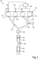
- Procédé d'exploitation d'un moteur à combustion interne (14), lors duquel des injections secondaires de carburant ont lieu au moyen d'une soupape d'injection dans au moins un cylindre (16, 18, 20, 22) du moteur à combustion interne (14) pour le soutien d'une régénération d'un filtre à particules (36) disposé dans une voie de gaz d'échappement du moteur à combustion interne (14) et monté en aval d'un catalyseur d'oxydation (34),
caractérisé en cequ'un décalage précoce (V) pour un instant d'ouverture (82) et un instant de fermeture (92) d'une soupape de sortie d'un cylindre (16, 18, 20, 22) du moteur à combustion interne (14) est réalisé de telle sorte qu'une compression intermédiaire de gaz d'échappement dans l'espace de combustion du cylindre (16, 18, 20, 22) a lieu, dans lequel le décalage précoce (V) de l'instant d'ouverture (82) et de l'instant de fermeture (92) est réalisé dans une première plage de température (Δϑ1) pour une température (ϑ) du catalyseur d'oxydation (34) etles injections secondaires ont lieu dans une seconde plage de température (Δϑ2) pour la température (ϑ) du catalyseur d'oxydation (34), dans lequel- une limite de plage supérieure (Δϑ1o) de la première plage de température (Δϑ1) présente une valeur inférieure à une limite de plage supérieure (Δϑ2o) de la seconde plage de température (Δϑ2) ;- une limite de plage inférieure de la seconde plage de température (Δϑ2) correspond à au moins approximativement une température d'amorçage (ϑA) du catalyseur d'oxydation (34) ;- la limite de plage supérieure (Δϑ1o) de la première plage de température (Δϑ1) tombe dans la seconde plage de température (Δϑ2), dans lequel la limite de plage supérieure (Δϑ1o) de la première plage de température (Δϑ1) se situe à pas plus d'environ 20 K au-dessus de la température d'amorçage (ϑA) ;- une réduction du décalage précoce (V) pour l'instant d'ouverture (82) et l'instant de fermeture (92) de la soupape de sortie a essentiellement lieu au sein de la première plage de température (Δϑ1) avec une température croissante (ϑ) du catalyseur d'oxydation (34) ;- une réduction de plus en plus forte du décalage précoce (V) de l'instant d'ouverture (82) et de l'instant de fermeture (92) a lieu dans la région de la température d'amorçage (ϑA) du catalyseur d'oxydation (34) avec une température croissante (ϑ) du catalyseur d'oxydation (34) ; et- lors de l'atteinte de la limite de plage supérieure (Δϑ1o) de la première plage de température (Δϑ1), le décalage précoce (V) des réglages de distribution est complètement annulé. - Procédé selon la revendication 1,
caractérisé en ce
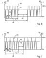
que les injections secondaires ont lieu dans au moins un des cylindres (16, 18, 20, 22) du moteur à combustion interne (14) de manière cadencée de telle sorte que des premiers intervalles de temps (38) de durée pouvant être prédéfinie dans lesquels des injections secondaires sont réalisées dans chaque cycle de travail d'un cylindre respectif alternent en succession directe avec des seconds intervalles de temps (40) de durée pouvant être prédéfinie dans lesquels les injections secondaires sont supprimées, et la durée du premier intervalle de temps (38) et/ou la durée du second intervalle de temps (40) sont prédéfinies en fonction de la température (ϑ) du catalyseur d'oxydation (34). - Procédé selon la revendication 2,
caractérisé en ce
qu'un renvoi divisé de gaz d'échappement des cylindres (16, 18, 20, 22) du moteur à combustion interne (14) est prévu dans une voie d'air entrant du moteur à combustion interne (14) de telle sorte que du gaz d'échappement uniquement d'une première partie des cylindres (16, 18, 20, 22) peut être acheminé à une proportion notable à la voie d'air entrant du moteur à combustion interne (14) et du gaz d'échappement de la seconde partie restante des cylindres (16, 18, 20, 22) est acheminé essentiellement entièrement et en renonçant à un renvoi au catalyseur d'oxydation (34), dans lequel des injections secondaires de carburant ont uniquement lieu auprès d'au moins un des cylindres (20, 22) de la seconde partie des cylindres (16, 18, 20, 22). - Procédé selon une des revendications 1 à 3,
caractérisé en ce
qu'un courant d'attaque (Iv) de la soupape d'injection est réglé pour la réalisation des injections secondaires en vue de l'actionnement d'un pointeau de soupape de la soupape d'injection en fonction d'une température (ϑ) du catalyseur d'oxydation (34). - Procédé selon la revendication 4,
caractérisé en ce
qu'une quantité d'injection secondaire (mNE) est limitée au-dessus d'une température pouvant être prédéfinie pour le catalyseur d'oxydation (34) en ce que dans le cas des injections secondaires, une amplitude de course de pointeau (H) réduite par rapport à une amplitude de course de pointeau maximale du pointeau de soupape de la soupape d'injection est réglée. - Moteur à combustion interne avec une voie de gaz d'échappement, dans lequel un catalyseur d'oxydation (34) et un filtre à particules (36) monté en aval du catalyseur d'oxydation (34) en termes d'écoulement sont disposés,
caractérisé en ce
que le moteur à combustion interne est réalisé avec des moyens de commande pour la réalisation d'un procédé selon une des revendications 1 à 5.
Applications Claiming Priority (2)
| Application Number | Priority Date | Filing Date | Title |
|---|---|---|---|
| DE102012018953.2A DE102012018953A1 (de) | 2012-09-26 | 2012-09-26 | Verfahren zum Betreiben einer Brennkraftmaschine und Brennkraftmaschine |
| PCT/EP2013/002469 WO2014048527A1 (fr) | 2012-09-26 | 2013-08-16 | Procédé permettant de faire fonctionner un moteur à combustion interne et moteur à combustion interne |
Publications (2)
| Publication Number | Publication Date |
|---|---|
| EP2900989A1 EP2900989A1 (fr) | 2015-08-05 |
| EP2900989B1 true EP2900989B1 (fr) | 2025-02-26 |
Family
ID=49035520
Family Applications (1)
| Application Number | Title | Priority Date | Filing Date |
|---|---|---|---|
| EP13753099.4A Active EP2900989B1 (fr) | 2012-09-26 | 2013-08-16 | Procédé permettant de faire fonctionner un moteur à combustion interne et moteur à combustion interne |
Country Status (4)
| Country | Link |
|---|---|
| US (1) | US9518486B2 (fr) |
| EP (1) | EP2900989B1 (fr) |
| DE (1) | DE102012018953A1 (fr) |
| WO (1) | WO2014048527A1 (fr) |
Families Citing this family (12)
| Publication number | Priority date | Publication date | Assignee | Title |
|---|---|---|---|---|
| US9488086B2 (en) * | 2013-12-23 | 2016-11-08 | Baohua Qi | Low pressure atomizing injector |
| JP6277941B2 (ja) * | 2014-11-05 | 2018-02-14 | 株式会社デンソー | 燃料噴射装置 |
| US10113453B2 (en) * | 2015-04-24 | 2018-10-30 | Randy Wayne McReynolds | Multi-fuel compression ignition engine |
| GB2545876A (en) * | 2015-08-13 | 2017-07-05 | Gm Global Tech Operations Llc | A method of operating an internal combustion engine |
| US9797358B2 (en) * | 2015-12-03 | 2017-10-24 | GM Global Technology Operations LLC | System and method for controlling an engine to remove soot deposits from the fuel injectors of the engine |
| DE102015016986A1 (de) * | 2015-12-24 | 2017-06-29 | Daimler Ag | Abgasnachbehandlungseinrichtung für eine Verbrennungskraftmaschine |
| US10378405B2 (en) * | 2016-01-20 | 2019-08-13 | Deere & Company | Method for managing temperatures in aftertreatment system |
| GB2550422B (en) * | 2016-05-20 | 2019-12-04 | Caterpillar Inc | Method of controlling operation of an exhaust gas treatment apparatus |
| US10215106B2 (en) * | 2016-12-22 | 2019-02-26 | Ford Global Technologies, Llc | System and method for adjusting exhaust valve timing |
| SE542977C2 (en) | 2019-02-20 | 2020-09-22 | Scania Cv Ab | Four-Stroke Internal Combustion Engine and Method of Operating Four-Stroke Internal Combustion Engine |
| WO2020200448A1 (fr) | 2019-04-04 | 2020-10-08 | Volvo Truck Corporation | Système de moteur à combustion interne et procédé d'actionnement de système à combustion interne |
| JP2025085210A (ja) * | 2023-11-24 | 2025-06-05 | いすゞ自動車株式会社 | 車両 |
Family Cites Families (10)
| Publication number | Priority date | Publication date | Assignee | Title |
|---|---|---|---|---|
| KR100504422B1 (ko) * | 2001-09-07 | 2005-07-29 | 미쓰비시 지도샤 고교(주) | 엔진의 배기 정화 장치 |
| US6826905B2 (en) * | 2002-06-04 | 2004-12-07 | International Engine Intellectual Property Company, Llc | Control strategy for regenerating a particulate filter in an exhaust system of an engine having a variable valve actuation mechanism |
| JP2004060443A (ja) | 2002-07-24 | 2004-02-26 | Mazda Motor Corp | エンジンの排気浄化装置 |
| JP3755494B2 (ja) | 2002-07-31 | 2006-03-15 | マツダ株式会社 | エンジンの排気浄化装置 |
| WO2005003537A1 (fr) | 2003-07-08 | 2005-01-13 | Nissan Motor Co., Ltd. | Dispositif servant a controler la combustion d'un moteur |
| US7104048B2 (en) * | 2004-04-30 | 2006-09-12 | General Motors Corporation | Low emission diesel particulate filter (DPF) regeneration |
| JP4017010B2 (ja) | 2006-02-01 | 2007-12-05 | いすゞ自動車株式会社 | 排気ガス浄化システムの制御方法及び排気ガス浄化システム |
| DE102006028436A1 (de) | 2006-06-21 | 2007-12-27 | Robert Bosch Gmbh | Verfahren zum Betreiben einer in einem Abgasbereich einer Brennkraftmaschine angeordneten Abgasreinigungsanlage |
| US7246595B1 (en) * | 2006-06-28 | 2007-07-24 | Ford Global Technologies, Llc | Diesel engine with differential cylinder group operation |
| DE102010014824B4 (de) * | 2010-04-13 | 2013-09-26 | Continental Automotive Gmbh | Verfahren zum Betreiben einer Brennkraftmaschine und Brennkraftmaschine |
-
2012
- 2012-09-26 DE DE102012018953.2A patent/DE102012018953A1/de not_active Withdrawn
-
2013
- 2013-08-16 US US14/431,184 patent/US9518486B2/en active Active
- 2013-08-16 EP EP13753099.4A patent/EP2900989B1/fr active Active
- 2013-08-16 WO PCT/EP2013/002469 patent/WO2014048527A1/fr not_active Ceased
Also Published As
| Publication number | Publication date |
|---|---|
| WO2014048527A1 (fr) | 2014-04-03 |
| EP2900989A1 (fr) | 2015-08-05 |
| US9518486B2 (en) | 2016-12-13 |
| US20150275723A1 (en) | 2015-10-01 |
| DE102012018953A1 (de) | 2014-03-27 |
Similar Documents
| Publication | Publication Date | Title |
|---|---|---|
| EP2900989B1 (fr) | Procédé permettant de faire fonctionner un moteur à combustion interne et moteur à combustion interne | |
| DE102004052272B4 (de) | Katalysatoraufbereitungsverfahren | |
| DE10161396B4 (de) | Verfahren zur Regeneration eines in einem Dieselmotor vorgesehenen Partikelfilters | |
| DE102010017575B4 (de) | Verfahren zum Betreiben einer fremdgezündeten Brennkraftmaschine und Brennkraftmaschine zur Durchführung eines derartigen Verfahrens | |
| EP3099905B1 (fr) | Procédé d'ajustement de la température d'un dispositif de retraitement de gaz d'échappement | |
| EP2394043B1 (fr) | Procede pour faire fonctionner un moteur a combustion interne equipe d'un systeme de depollution des gaz d'echappement | |
| DE102005045294B4 (de) | Verfahren zum Betreiben einer Brennkraftmaschine | |
| DE19847874A1 (de) | Verfahren zur Stickoxidreduzierung im Abgas einer mager betriebenen Brennkraftmaschine | |
| WO2010089039A1 (fr) | Procédé pour faire fonctionner un moteur à combustion interne équipé d'un système de dépollution des gaz d'échappement à catalyseur scr | |
| DE102011004522A1 (de) | Verfahren zum Betreiben einer fremdgezündete Brennkraftmaschine mit Abgasnachbehandlung und Brennkraftmaschine zur Durchführung eines derartigen Verfahrens | |
| EP2131019A1 (fr) | Procédé de gestion d'un dispositif de traitement de gaz d'échappement et dispositif de traitement de gaz d'échappement | |
| DE102012018967B4 (de) | Verfahren zum Regenerieren eines Partikelfilters und Anordnung einer Abgasanlage an einer Verbrennungskraftmaschine eines Fahrzeugs | |
| EP1682754B1 (fr) | Moteur a combustion interne polycylindrique, et procede pour faire fonctionner un moteur a combustion interne polycylindrique | |
| DE102012018954A1 (de) | Verfahren zum Betreiben einer Brennkraftmaschine eines Fahrzeugs | |
| AT521759A1 (de) | Verfahren und Ottomotoranordnung mit einer verbesserten Abgasnachbehandlung durch eine Regenerationsstrategie | |
| DE102015005650A1 (de) | Verfahren zum Betreiben einer Abgasanlage eines Fahrzeugs | |
| DE102005025737A1 (de) | Betriebsverfahren für eine Einspritzbrennkraftmaschine | |
| DE102012022156B4 (de) | Verfahren zur Kraftstoffeinspritzung in einen Dieselmotor sowie Steuereinrichtung | |
| DE102017201399B4 (de) | Abgasnachbehandlungssystem | |
| DE102009048169A1 (de) | Verfahren zum Betreiben eines Abgasnachbehandlungssystems | |
| DE102006062650B4 (de) | Verfahren zur Reaktivierung edelmetallhaltiger Abgasnachbehandlungskomponenten von dauernd magerbetriebenenen Brennkraftmaschinen und Steuereinheit zur Steuerung des Verfahrens | |
| EP1837496B1 (fr) | Moteur à combustion interne avec un système de traitement combiné des gaz d'échappement et procédé d'opération d'un tel moteur à combustion interne | |
| DE102006042875A1 (de) | Verfahren zum Einspritzen unverbrannter Kohlenwasserstoffe in den Abgastrakt einer Brennkraftmaschine und Brennkraftmaschine zur Durchführung eines derartigen Verfahrens | |
| WO2015176945A1 (fr) | Procédé et dispositif de gestion de la température des gaz d'échappement d'un moteur à combustion interne | |
| DE102009006059A1 (de) | Verfahren zum Betreiben einer Verbrennungskraftmaschine und Verbrennungskraftmaschine |
Legal Events
| Date | Code | Title | Description |
|---|---|---|---|
| PUAI | Public reference made under article 153(3) epc to a published international application that has entered the european phase |
Free format text: ORIGINAL CODE: 0009012 |
|
| 17P | Request for examination filed |
Effective date: 20150305 |
|
| AK | Designated contracting states |
Kind code of ref document: A1 Designated state(s): AL AT BE BG CH CY CZ DE DK EE ES FI FR GB GR HR HU IE IS IT LI LT LU LV MC MK MT NL NO PL PT RO RS SE SI SK SM TR |
|
| AX | Request for extension of the european patent |
Extension state: BA ME |
|
| DAX | Request for extension of the european patent (deleted) | ||
| RAP1 | Party data changed (applicant data changed or rights of an application transferred) |
Owner name: DAIMLER AG |
|
| STAA | Information on the status of an ep patent application or granted ep patent |
Free format text: STATUS: EXAMINATION IS IN PROGRESS |
|
| 17Q | First examination report despatched |
Effective date: 20210323 |
|
| RAP1 | Party data changed (applicant data changed or rights of an application transferred) |
Owner name: DAIMLER TRUCK AG |
|
| P01 | Opt-out of the competence of the unified patent court (upc) registered |
Effective date: 20230609 |
|
| GRAP | Despatch of communication of intention to grant a patent |
Free format text: ORIGINAL CODE: EPIDOSNIGR1 |
|
| STAA | Information on the status of an ep patent application or granted ep patent |
Free format text: STATUS: GRANT OF PATENT IS INTENDED |
|
| RIC1 | Information provided on ipc code assigned before grant |
Ipc: F02M 26/43 20160101ALI20240820BHEP Ipc: F02M 26/15 20160101ALI20240820BHEP Ipc: F02D 41/04 20060101ALI20240820BHEP Ipc: F02D 13/02 20060101ALI20240820BHEP Ipc: F01N 9/00 20060101ALI20240820BHEP Ipc: F01N 3/20 20060101ALI20240820BHEP Ipc: F01N 3/10 20060101ALI20240820BHEP Ipc: F02D 41/00 20060101ALI20240820BHEP Ipc: F01N 3/023 20060101ALI20240820BHEP Ipc: F01N 13/02 20100101ALI20240820BHEP Ipc: F02D 41/40 20060101ALI20240820BHEP Ipc: F02D 41/02 20060101AFI20240820BHEP |
|
| INTG | Intention to grant announced |
Effective date: 20240918 |
|
| GRAS | Grant fee paid |
Free format text: ORIGINAL CODE: EPIDOSNIGR3 |
|
| GRAA | (expected) grant |
Free format text: ORIGINAL CODE: 0009210 |
|
| STAA | Information on the status of an ep patent application or granted ep patent |
Free format text: STATUS: THE PATENT HAS BEEN GRANTED |
|
| AK | Designated contracting states |
Kind code of ref document: B1 Designated state(s): AL AT BE BG CH CY CZ DE DK EE ES FI FR GB GR HR HU IE IS IT LI LT LU LV MC MK MT NL NO PL PT RO RS SE SI SK SM TR |
|
| REG | Reference to a national code |
Ref country code: GB Ref legal event code: FG4D Free format text: NOT ENGLISH |
|
| REG | Reference to a national code |
Ref country code: CH Ref legal event code: EP |
|
| REG | Reference to a national code |
Ref country code: DE Ref legal event code: R081 Ref document number: 502013016573 Country of ref document: DE Owner name: DAIMLER TRUCK AG, DE Free format text: FORMER OWNER: ANMELDERANGABEN UNKLAR / UNVOLLSTAENDIG, 80297 MUENCHEN, DE |
|
| REG | Reference to a national code |
Ref country code: DE Ref legal event code: R096 Ref document number: 502013016573 Country of ref document: DE |
|
| REG | Reference to a national code |
Ref country code: IE Ref legal event code: FG4D Free format text: LANGUAGE OF EP DOCUMENT: GERMAN |
|
| REG | Reference to a national code |
Ref country code: SE Ref legal event code: TRGR |
|
| REG | Reference to a national code |
Ref country code: NL Ref legal event code: MP Effective date: 20250226 |
|
| PG25 | Lapsed in a contracting state [announced via postgrant information from national office to epo] |
Ref country code: RS Free format text: LAPSE BECAUSE OF FAILURE TO SUBMIT A TRANSLATION OF THE DESCRIPTION OR TO PAY THE FEE WITHIN THE PRESCRIBED TIME-LIMIT Effective date: 20250526 |
|
| PG25 | Lapsed in a contracting state [announced via postgrant information from national office to epo] |
Ref country code: FI Free format text: LAPSE BECAUSE OF FAILURE TO SUBMIT A TRANSLATION OF THE DESCRIPTION OR TO PAY THE FEE WITHIN THE PRESCRIBED TIME-LIMIT Effective date: 20250226 |
|
| PG25 | Lapsed in a contracting state [announced via postgrant information from national office to epo] |
Ref country code: PL Free format text: LAPSE BECAUSE OF FAILURE TO SUBMIT A TRANSLATION OF THE DESCRIPTION OR TO PAY THE FEE WITHIN THE PRESCRIBED TIME-LIMIT Effective date: 20250226 |
|
| PG25 | Lapsed in a contracting state [announced via postgrant information from national office to epo] |
Ref country code: ES Free format text: LAPSE BECAUSE OF FAILURE TO SUBMIT A TRANSLATION OF THE DESCRIPTION OR TO PAY THE FEE WITHIN THE PRESCRIBED TIME-LIMIT Effective date: 20250226 |
|
| REG | Reference to a national code |
Ref country code: LT Ref legal event code: MG9D |
|
| PG25 | Lapsed in a contracting state [announced via postgrant information from national office to epo] |
Ref country code: IS Free format text: LAPSE BECAUSE OF FAILURE TO SUBMIT A TRANSLATION OF THE DESCRIPTION OR TO PAY THE FEE WITHIN THE PRESCRIBED TIME-LIMIT Effective date: 20250626 Ref country code: NO Free format text: LAPSE BECAUSE OF FAILURE TO SUBMIT A TRANSLATION OF THE DESCRIPTION OR TO PAY THE FEE WITHIN THE PRESCRIBED TIME-LIMIT Effective date: 20250526 |
|
| PG25 | Lapsed in a contracting state [announced via postgrant information from national office to epo] |
Ref country code: NL Free format text: LAPSE BECAUSE OF FAILURE TO SUBMIT A TRANSLATION OF THE DESCRIPTION OR TO PAY THE FEE WITHIN THE PRESCRIBED TIME-LIMIT Effective date: 20250226 |
|
| PG25 | Lapsed in a contracting state [announced via postgrant information from national office to epo] |
Ref country code: HR Free format text: LAPSE BECAUSE OF FAILURE TO SUBMIT A TRANSLATION OF THE DESCRIPTION OR TO PAY THE FEE WITHIN THE PRESCRIBED TIME-LIMIT Effective date: 20250226 |
|
| PG25 | Lapsed in a contracting state [announced via postgrant information from national office to epo] |
Ref country code: PT Free format text: LAPSE BECAUSE OF FAILURE TO SUBMIT A TRANSLATION OF THE DESCRIPTION OR TO PAY THE FEE WITHIN THE PRESCRIBED TIME-LIMIT Effective date: 20250626 Ref country code: LV Free format text: LAPSE BECAUSE OF FAILURE TO SUBMIT A TRANSLATION OF THE DESCRIPTION OR TO PAY THE FEE WITHIN THE PRESCRIBED TIME-LIMIT Effective date: 20250226 |
|
| PG25 | Lapsed in a contracting state [announced via postgrant information from national office to epo] |
Ref country code: GR Free format text: LAPSE BECAUSE OF FAILURE TO SUBMIT A TRANSLATION OF THE DESCRIPTION OR TO PAY THE FEE WITHIN THE PRESCRIBED TIME-LIMIT Effective date: 20250527 Ref country code: BG Free format text: LAPSE BECAUSE OF FAILURE TO SUBMIT A TRANSLATION OF THE DESCRIPTION OR TO PAY THE FEE WITHIN THE PRESCRIBED TIME-LIMIT Effective date: 20250226 |
|
| PG25 | Lapsed in a contracting state [announced via postgrant information from national office to epo] |
Ref country code: SM Free format text: LAPSE BECAUSE OF FAILURE TO SUBMIT A TRANSLATION OF THE DESCRIPTION OR TO PAY THE FEE WITHIN THE PRESCRIBED TIME-LIMIT Effective date: 20250226 |
|
| PG25 | Lapsed in a contracting state [announced via postgrant information from national office to epo] |
Ref country code: DK Free format text: LAPSE BECAUSE OF FAILURE TO SUBMIT A TRANSLATION OF THE DESCRIPTION OR TO PAY THE FEE WITHIN THE PRESCRIBED TIME-LIMIT Effective date: 20250226 |
|
| PGFP | Annual fee paid to national office [announced via postgrant information from national office to epo] |
Ref country code: DE Payment date: 20250827 Year of fee payment: 13 |
|
| PG25 | Lapsed in a contracting state [announced via postgrant information from national office to epo] |
Ref country code: IT Free format text: LAPSE BECAUSE OF FAILURE TO SUBMIT A TRANSLATION OF THE DESCRIPTION OR TO PAY THE FEE WITHIN THE PRESCRIBED TIME-LIMIT Effective date: 20250226 |
|
| PGFP | Annual fee paid to national office [announced via postgrant information from national office to epo] |
Ref country code: GB Payment date: 20250826 Year of fee payment: 13 |
|
| PGFP | Annual fee paid to national office [announced via postgrant information from national office to epo] |
Ref country code: FR Payment date: 20250825 Year of fee payment: 13 |
|
| PGFP | Annual fee paid to national office [announced via postgrant information from national office to epo] |
Ref country code: SE Payment date: 20250825 Year of fee payment: 13 |
|
| PG25 | Lapsed in a contracting state [announced via postgrant information from national office to epo] |
Ref country code: CZ Free format text: LAPSE BECAUSE OF FAILURE TO SUBMIT A TRANSLATION OF THE DESCRIPTION OR TO PAY THE FEE WITHIN THE PRESCRIBED TIME-LIMIT Effective date: 20250226 Ref country code: EE Free format text: LAPSE BECAUSE OF FAILURE TO SUBMIT A TRANSLATION OF THE DESCRIPTION OR TO PAY THE FEE WITHIN THE PRESCRIBED TIME-LIMIT Effective date: 20250226 |
|
| PG25 | Lapsed in a contracting state [announced via postgrant information from national office to epo] |
Ref country code: RO Free format text: LAPSE BECAUSE OF FAILURE TO SUBMIT A TRANSLATION OF THE DESCRIPTION OR TO PAY THE FEE WITHIN THE PRESCRIBED TIME-LIMIT Effective date: 20250226 |
|
| PG25 | Lapsed in a contracting state [announced via postgrant information from national office to epo] |
Ref country code: SK Free format text: LAPSE BECAUSE OF FAILURE TO SUBMIT A TRANSLATION OF THE DESCRIPTION OR TO PAY THE FEE WITHIN THE PRESCRIBED TIME-LIMIT Effective date: 20250226 |
|
| REG | Reference to a national code |
Ref country code: DE Ref legal event code: R097 Ref document number: 502013016573 Country of ref document: DE |
|
| PLBE | No opposition filed within time limit |
Free format text: ORIGINAL CODE: 0009261 |
|
| STAA | Information on the status of an ep patent application or granted ep patent |
Free format text: STATUS: NO OPPOSITION FILED WITHIN TIME LIMIT |
|
| REG | Reference to a national code |
Ref country code: CH Ref legal event code: L10 Free format text: ST27 STATUS EVENT CODE: U-0-0-L10-L00 (AS PROVIDED BY THE NATIONAL OFFICE) Effective date: 20260107 |
|
| 26N | No opposition filed |
Effective date: 20251127 |
|
| REG | Reference to a national code |
Ref country code: CH Ref legal event code: H13 Free format text: ST27 STATUS EVENT CODE: U-0-0-H10-H13 (AS PROVIDED BY THE NATIONAL OFFICE) Effective date: 20260324 |
|
| PG25 | Lapsed in a contracting state [announced via postgrant information from national office to epo] |
Ref country code: MC Free format text: LAPSE BECAUSE OF FAILURE TO SUBMIT A TRANSLATION OF THE DESCRIPTION OR TO PAY THE FEE WITHIN THE PRESCRIBED TIME-LIMIT Effective date: 20250226 |
|
| PG25 | Lapsed in a contracting state [announced via postgrant information from national office to epo] |
Ref country code: LU Free format text: LAPSE BECAUSE OF NON-PAYMENT OF DUE FEES Effective date: 20250816 |