EP2901036B1 - Elektromagnetisch betätigbare bremsanordnung und elektromotor - Google Patents
Elektromagnetisch betätigbare bremsanordnung und elektromotor Download PDFInfo
- Publication number
- EP2901036B1 EP2901036B1 EP13752824.6A EP13752824A EP2901036B1 EP 2901036 B1 EP2901036 B1 EP 2901036B1 EP 13752824 A EP13752824 A EP 13752824A EP 2901036 B1 EP2901036 B1 EP 2901036B1
- Authority
- EP
- European Patent Office
- Prior art keywords
- magnet body
- arrangement according
- braking arrangement
- armature disc
- damping plate
- Prior art date
- Legal status (The legal status is an assumption and is not a legal conclusion. Google has not performed a legal analysis and makes no representation as to the accuracy of the status listed.)
- Active
Links
Images

Classifications
-
- F—MECHANICAL ENGINEERING; LIGHTING; HEATING; WEAPONS; BLASTING
- F16—ENGINEERING ELEMENTS AND UNITS; GENERAL MEASURES FOR PRODUCING AND MAINTAINING EFFECTIVE FUNCTIONING OF MACHINES OR INSTALLATIONS; THERMAL INSULATION IN GENERAL
- F16D—COUPLINGS FOR TRANSMITTING ROTATION; CLUTCHES; BRAKES
- F16D55/00—Brakes with substantially-radial braking surfaces pressed together in axial direction, e.g. disc brakes
- F16D55/24—Brakes with substantially-radial braking surfaces pressed together in axial direction, e.g. disc brakes with a plurality of axially-movable discs, lamellae, or pads, pressed from one side towards an axially-located member
- F16D55/26—Brakes with substantially-radial braking surfaces pressed together in axial direction, e.g. disc brakes with a plurality of axially-movable discs, lamellae, or pads, pressed from one side towards an axially-located member without self-tightening action
- F16D55/28—Brakes with only one rotating disc
-
- F—MECHANICAL ENGINEERING; LIGHTING; HEATING; WEAPONS; BLASTING
- F16—ENGINEERING ELEMENTS AND UNITS; GENERAL MEASURES FOR PRODUCING AND MAINTAINING EFFECTIVE FUNCTIONING OF MACHINES OR INSTALLATIONS; THERMAL INSULATION IN GENERAL
- F16D—COUPLINGS FOR TRANSMITTING ROTATION; CLUTCHES; BRAKES
- F16D59/00—Self-acting brakes, e.g. coming into operation at a predetermined speed
- F16D59/02—Self-acting brakes, e.g. coming into operation at a predetermined speed spring-loaded and adapted to be released by mechanical, fluid, or electromagnetic means
-
- F—MECHANICAL ENGINEERING; LIGHTING; HEATING; WEAPONS; BLASTING
- F16—ENGINEERING ELEMENTS AND UNITS; GENERAL MEASURES FOR PRODUCING AND MAINTAINING EFFECTIVE FUNCTIONING OF MACHINES OR INSTALLATIONS; THERMAL INSULATION IN GENERAL
- F16D—COUPLINGS FOR TRANSMITTING ROTATION; CLUTCHES; BRAKES
- F16D65/00—Parts or details
- F16D65/0006—Noise or vibration control
-
- F—MECHANICAL ENGINEERING; LIGHTING; HEATING; WEAPONS; BLASTING
- F16—ENGINEERING ELEMENTS AND UNITS; GENERAL MEASURES FOR PRODUCING AND MAINTAINING EFFECTIVE FUNCTIONING OF MACHINES OR INSTALLATIONS; THERMAL INSULATION IN GENERAL
- F16D—COUPLINGS FOR TRANSMITTING ROTATION; CLUTCHES; BRAKES
- F16D65/00—Parts or details
- F16D65/02—Braking members; Mounting thereof
- F16D65/12—Discs; Drums for disc brakes
-
- F—MECHANICAL ENGINEERING; LIGHTING; HEATING; WEAPONS; BLASTING
- F16—ENGINEERING ELEMENTS AND UNITS; GENERAL MEASURES FOR PRODUCING AND MAINTAINING EFFECTIVE FUNCTIONING OF MACHINES OR INSTALLATIONS; THERMAL INSULATION IN GENERAL
- F16D—COUPLINGS FOR TRANSMITTING ROTATION; CLUTCHES; BRAKES
- F16D55/00—Brakes with substantially-radial braking surfaces pressed together in axial direction, e.g. disc brakes
- F16D2055/0004—Parts or details of disc brakes
- F16D2055/0058—Fully lined, i.e. braking surface extending over the entire disc circumference
-
- F—MECHANICAL ENGINEERING; LIGHTING; HEATING; WEAPONS; BLASTING
- F16—ENGINEERING ELEMENTS AND UNITS; GENERAL MEASURES FOR PRODUCING AND MAINTAINING EFFECTIVE FUNCTIONING OF MACHINES OR INSTALLATIONS; THERMAL INSULATION IN GENERAL
- F16D—COUPLINGS FOR TRANSMITTING ROTATION; CLUTCHES; BRAKES
- F16D65/00—Parts or details
- F16D65/02—Braking members; Mounting thereof
- F16D2065/13—Parts or details of discs or drums
- F16D2065/134—Connection
- F16D2065/1392—Connection elements
- F16D2065/1396—Ancillary resilient elements, e.g. anti-rattle or retraction springs
-
- F—MECHANICAL ENGINEERING; LIGHTING; HEATING; WEAPONS; BLASTING
- F16—ENGINEERING ELEMENTS AND UNITS; GENERAL MEASURES FOR PRODUCING AND MAINTAINING EFFECTIVE FUNCTIONING OF MACHINES OR INSTALLATIONS; THERMAL INSULATION IN GENERAL
- F16D—COUPLINGS FOR TRANSMITTING ROTATION; CLUTCHES; BRAKES
- F16D2121/00—Type of actuator operation force
- F16D2121/18—Electric or magnetic
- F16D2121/20—Electric or magnetic using electromagnets
- F16D2121/22—Electric or magnetic using electromagnets for releasing a normally applied brake
Definitions
- the invention relates to an electromagnetically operable brake assembly and an electric motor.
- the invention is therefore the object of developing an electromagnetically actuated brake assembly, the environmental protection during operation and the reliability is to be improved.
- the object is achieved in the electromagnetically actuated brake assembly according to the features specified in claim 1 and in the electric motor according to the features indicated in claim 15.
- the advantage here is that the noise emission can be reduced and thus the environmental protection is improved. Because the environment is burdened with lower noise when operating the brake.
- the damping plate rests on the elevation of the armature disk and is thus radially outwardly deformable. Thus, when the armature disk is moved towards the magnet body, a contact of the damping metal sheet with the magnet body is possible in the radially outward region, and thus damping, ie deceleration, of the armature disk.
- the elastic bearing of the damping plate on the armature disc reduces or prevents the noise generated on impact.
- an angle sensor is arranged on the axial side of the magnet body facing away from the armature disk, wherein the angle sensor comprises a sensor housing, which is connected directly or via an adapter plate with the magnetic body, and wherein a Sensorotorteil is arranged surrounded by the sensor housing, which is rotatably connected to the shaft, and wherein the adapter plate is made of an amagnetic, diamagnetic or paramagnetic material, in particular aluminum or plastic.
- the material of the adapter plate has a greater absorption for structure-borne noise with a frequency between 1 Hz and 100 kHz than the material of the magnetic body.
- the advantage here is that caused by the armature disk and not fully attenuated by the damping disk shock wave through the adapter plate is further attenuated and thus amplification of the damping to the angle sensor is effected. Due to the appropriate choice of material, protection against magnetic fields and shock waves, ie structure-borne noise, can be achieved.
- the radial distance range is a partial region of the radial distance range covered by the brake coil.
- the advantage here is that the survey is arranged radially in the covered by the brake coil radial distance range.
- the magnetic body together with the brake coil and associated coil carrier and casting compound axially deepened executable so that an air space for damping plate out arises. In this way is a touch of the damping plate prevented, so that it rests undisturbed on the axial elevation of the armature disc.
- the brake coil and / or a coil carrier of the brake coil by means of potting compound is held in the magnetic body.
- the advantage here is that a simple connection technology, in particular a cohesive connection technology, can be used.
- spring elements which are supported on the magnetic body press against the armature disk, in particular in the axial direction.
- the damping plate is located on the survey and / or touches the survey.
- the advantage here is that on the support surface, the armature disc decelerating force can be introduced, which is generated upon contact of the damping plate by the magnetic body by means of deformation of the damping plate.
- the damping plate is between the damping plate and potting an airspace.
- the advantage here is that the touch of the damping plate takes place by the magnetic body in a defined range, ie radially outside of the survey of the survey covered radial distance range.
- the spring elements push the armature disk toward the lining carrier, which is thus pressed onto a braking surface
- the braking surface is arranged on a housing part and / or end shield, which is connected to the magnet body,
- the shaft is mounted in the braking surface having part by means of at least one bearing.
- the armature disc against the spring force generated by the spring elements to the magnet body out dressed.
- the advantage here is that the brake pad carrier gains axial clearance and thus moves away from the braking surface.
- the brake coil is an annular coil which is received in an annular recess of the magnetic body
- the ring axis is the shaft axis.
- the advantage here is that a simple production is possible, in particular by the magnetic body is executed pot-shaped, with a centrally disposed center leg opens at the bottom of the pot.
- the magnetic body protrudes radially outside of the survey of the survey covered radial distance range axially further to the armature disk out than in this radial distance range or radially further inside.
- the advantage here is that the touch of the damping plate takes place through the magnetic body in a defined manner, ie only radially outside of the radial distance covered by the survey.
- the damping plate is made of sheet steel and / or designed as a perforated disc.
- the advantage here is that an effective noise attenuation can be achieved without a too large air gap is necessary.
- the steel sheet has a high stability and, on the other hand, that the steel sheet is ferromagnetic.
- the armature disk made of a ferromagnetic material, such as steel or iron, executed and / or the magnetic body is made of cast steel.
- the advantage here is that with a low coil current rapid ventilation is possible, although the spring elements cause high spring forces.
- the lining carrier has an internal toothing which is in engagement with an external toothing connected to the shaft or arranged on the shaft, in particular wherein the toothing extends axially.
- the shaft is a rotor shaft of the electric motor.
- the advantage here is that the electric motor with brake assembly comprehensive drive, such as inverter-fed geared motor, quiet and thus environmentally friendly operation.
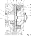
- the shaft 1 is mounted via a bearing 2 received in the bearing plate 3 of an electric motor.
- the shaft 1 here is the rotor shaft of the electric motor and is designed with a toothing or rotatably connected to a toothing having a toothed part, wherein the toothing is the driving toothing of a motor-driven transmission.
- the bearing plate 3 is connected to the stator housing and / or other housing parts of the electric motor.
- a magnetic body 11 preferably made of cast steel, in particular GGG cast, connected, in particular screw-connected with intermediate spacers.
- the magnetic body 11 can also be labeled as a bobbin.
- the toothing is mounted, the teeth of which extend in the axial direction.
- the toothing is an involute toothing.
- a lining carrier 4 which faces at least axially on both sides, that is to say to the bearing plate 3 and also to the magnetic body 11, has a respective brake lining or from one Brake lining is made, has an internal toothing, by means of which the lining carrier 4 rotatably but axially displaceably connected to the toothing of the shaft 1 and the ring member 15th
- An axially between the lining carrier 4 and magnetic body 11 arranged axially displaceable but non-rotatably connected to the magnetic body associated armature disc 6 is made of a ferromagnetic material, such as steel or the like.
- the magnetic body 11 has an annular recess into which a toroidal coil accommodated in a coil carrier 12 made of plastic, which is also referred to as a brake coil 10, is inserted.
- the magnetic body thus has a cup-shaped appearance, wherein a centrally disposed center leg is formed on the magnetic body 11.
- the brake coil 10 is held together with coil support 12 in the annular recess of the magnetic body 11 by means of potting compound.
- an adapter plate 13 is arranged, on whose side facing away from the magnetic body 11 axial side, a sensor housing 14 of an angle sensor connected, in particular screw-connected.
- a sensor rotor part of the angle sensor is rotatably connected, so that the angular position of the surrounded by the sensor housing 14 sensor rotor part is detectable.
- the sensor housing 14 is in FIG. 1 not shown cut.
- the adapter plate 13 is made of a non-magnetic and / or diamagnetic material, such as aluminum or plastic, so that a magnetic decoupling can be reached between the magnetic body and the angle sensor.
- the adapter plate 13 has a first interface for connection to the magnetic body 11 and a second interface for connection to the sensor housing 14.
- various sensor housing on the same magnetic body 11 are connected.
- an always identical angle sensor with different magnetic bodies 11 can be connected by a respective respective adapter is assigned to the respective sensor housing 14, these adapters to the magnetic body 11 always have the same interface, the angle sensor, however, always the same interface.
- the term "interface” is understood to mean the geometric arrangement of steps and / or the drilling pattern of bores in the connection region of the respective component.
- a damping system with a damping plate 21 is provided. This is connected to the armature disk 4, in particular positively connected and / or riveted.
- the damping plate 21 is designed as a flat piece of sheet metal and has recesses for the continuous spring elements 9.
- the damping plate 21 rests on a collar 20, ie an annular elevation, on the armature disk 6.
- This survey 20 is facing the magnetic body 11 and arranged within the covered by the brake coil 10 radial distance range.
- an air space 7 is arranged.
- correspondingly little potting compound 8 is used when pouring into the annular recess of the magnetic body 11.
- the air space 7 covers in the radial direction the area covered by the elevation 20
- the magnetic body presses at sunken brake, so when energized brake coil 10, the damping plate 21.
- the damping plate 21 is also at sunken Brake, so energized brake coil 10, not touched by potting compound 8 or the magnetic body 11.
- the energy of accelerated during the energizing of the brake coil 10 armature plate 6 is at least partially removed via the damping plate 21 and thus attenuates the resulting impact noise by means of the deformation of the damping plate 21st
- the axial extent of the elevation 20 is smaller, in particular at least five times smaller than the axial extent of the air space. 7
- the survey 20 is designed annular. It is similar to a circumferential collar.
- the damping plate 21 is in turn as well as the armature disc ferromagnetic.
- the ring member 15 is formed integrally with the shaft 3.
Landscapes
- Engineering & Computer Science (AREA)
- General Engineering & Computer Science (AREA)
- Mechanical Engineering (AREA)
- Physics & Mathematics (AREA)
- Electromagnetism (AREA)
- Braking Arrangements (AREA)
Description
- Die Erfindung betrifft eine elektromagnetisch betätigbare Bremsanordnung und einen Elektromotor.
- Es ist allgemein bekannt, dass bei einer elektromagnetisch betätigbaren Bremsanordnung eines Elektromotors eine Ankerscheibe in Richtung auf einen Magnetkörper hin beschleunigt wird.
- Aus der
DE 196 22 983 C1 ist eine Bremse bekannt, an deren Ankerscheibe ein Dämpfungsblech befestigt ist und somit eine Einheit bildet. - Aus der
DE 10 2010 049747 A1 ist ein Bausatz zur Herstellung unterschiedlicher Elektromotoren einer Baureihe von Elektromotoren bekannt. - Aus der
US 5 274 290 A ist eine elektromagnetisch betätigbare Bremse bekannt. - Aus der
DE 89 13 767 U1 ist eine elektromagnetische Bremse bekannt. - Aus der
EP 0 222 312 A1 ist eine Federdruckbremse bekannt. - Der Erfindung liegt daher die Aufgabe zugrunde, eine elektromagnetisch betätigbare Bremsanordnung weiterzubilden, wobei der Umweltschutz beim Betrieb und die Funktionssicherheit zu verbessern ist.
- Erfindungsgemäß wird die Aufgabe bei der elektromagnetisch betätigbaren Bremsanordnung nach den in Anspruch 1 und bei dem Elektromotor nach den in Anspruch 15 angegebenen Merkmalen gelöst.
- Von Vorteil ist dabei, dass die Geräuschemission verringerbar ist und somit der Umweltschutz verbessert ist. Denn die Umwelt ist mit geringeren Geräuschen beim Betätigen der Bremse belastet. Das Dämpfungsblech liegt auf der Erhebung der Ankerscheibe auf und ist somit radial außerhalb verformbar. Somit ist beim Heranbewegen der Ankerscheibe auf den Magnetkörper zu in diesem radial außerhalb liegenden Bereich eine Berührung des Dämpfungsblechs durch den Magnetkörper ausführbar und somit ein Abdämpfen, also Abbremsen, der Ankerscheibe. Durch die elastische Auflagerung des Dämpfungsblechs an der Ankerscheibe wird das beim Auftreffen erzeugte Geräusch vermindert oder verhindert.
- Mittels der Dämpfung ist es ermöglicht, einen Winkelsensor direkt am Magnetkörper anzuordnen, obwohl das Abbremsen der Ankerscheibe eine Körperschallwelle auslöst, die größtenteils auch in axialer Richtung durch den Magnetkörper durchläuft.
- Gemäß Anspruch 1 ist an der von der Ankerscheibe abgewandten axialen Seite des Magnetkörpers ein Winkelsensor angeordnet,
wobei der Winkelsensor ein Sensorgehäuse aufweist, das direkt oder über eine Adapterplatte mit dem Magnetkörper verbunden ist, und wobei vom Sensorgehäuse umgeben ein Sensorrotorteil angeordnet ist, das mit der Welle drehfest verbunden ist,
und wobei die Adapterplatte aus einem amagnetischem, diamagnetischen oder paramagnetischem Werkstoff, insbesondere Aluminium oder Kunststoff, gefertigt ist. - Das Material der Adapterplatte weist eine größere Absorption für Körperschall mit einer Frequenz zwischen 1 Hz und 100 kHz auf als das Material des Magnetkörpers. Von Vorteil ist dabei, dass die von der Ankerscheibe bewirkte und von der Dämpfungsscheibe nicht vollständig abgedämpfte Schockwelle durch die Adapterplatte weiter abdämpfbar ist und somit eine Verstärkung der Abdämpfung zum Winkelsensor hin bewirkbar ist. Durch die geeignete Materialwahl ist ein Schutz vor magnetischen Feldern und Schockwellen, also Körperschall, erreichbar.
- Bei einer vorteilhaften Ausgestaltung ist der Radialabstandsbereich ein Teilbereich des von der Bremsspule überdeckten Radialabstandsbereichs. Von Vorteil ist dabei, dass die Erhebung radial im von der Bremsspule überdeckten Radialabstandsbereich angeordnet ist. Somit ist. Somit ist in diesem Bereich der Magnetkörper samt Bremsspule und zugehörigem Spulenträger sowie Vergussmasse axial vertieft ausführbar, so dass ein Luftraum zum Dämpfungsblech hin entsteht. Auf diese Weise ist eine Berührung des Dämpfungsblechs verhindert, so dass es ungestört aufliegt auf der axialen Erhebung der Ankerscheibe.
- Bei einer vorteilhaften Ausgestaltung ist die Bremsspule und/oder ein Spulenträger der Bremsspule mittels Vergussmasse gehalten in dem Magnetkörper. Von Vorteil ist dabei, dass eine einfache Verbindungstechnik, insbesondere eine stoffschlüssige Verbindungstechnik, verwendbar ist.
- Bei einer vorteilhaften Ausgestaltung drücken sich am Magnetkörper abstützende Federelemente auf die Ankerscheibe, insbesondere in axialer Richtung. Von Vorteil ist dabei, dass bei Nichtbestromung der Bremsspule, beispielsweise bei Stromausfall, die Bremse einfällt und ein Lüften verhindert ist. Somit ist die Sicherheit erhöht.
- Bei einer vorteilhaften Ausgestaltung liegt das Dämpfungsblech auf der Erhebung auf und/oder berührt die Erhebung. Von Vorteil ist dabei, dass über die Auflagefläche die die Ankerscheibe abbremsende Kraft einleitbar ist, welche bei Berührung des Dämpfungsblechs durch den Magnetkörper mittels Verformung des Dämpfungsblechs erzeugbar ist.
- Bei einer vorteilhaften Ausgestaltung ist zwischen Dämpfungsblech und Vergussmasse ein Luftraum. Von Vorteil ist dabei, dass die Berührung des Dämpfungsblechs durch den Magnetkörper in einem definierten Bereich erfolgt, also radial außerhalb des von der Erhebung überdeckten Radialabstandsbereichs.
- Bei einer vorteilhaften Ausgestaltung drücken bei nicht bestromter Bremsspule die Federelemente die Ankerscheibe zum Belagträger hin, der somit auf eine Bremsfläche gedrückt wird,
- insbesondere wobei die Bremsfläche auf einem Gehäuseteil und/oder Lagerschild angeordnet ist, das mit dem Magnetkörper verbunden ist,
- insbesondere wobei die Welle im die Bremsfläche aufweisenden Teil gelagert ist mittels zumindest eines Lagers. Von Vorteil ist dabei, dass die Sicherheit erhöht ist, da ein Einfallen der Bremse bei Stromausfall oder dergleichen vorgesehen ist.
- Bei einer vorteilhaften Ausgestaltung wird bei bestromter Bremsspule die Ankerscheibe entgegen der von den Federelementen erzeugten Federkraft zum Magnetkörper hin angezogen. Von Vorteil ist dabei, dass der Bremsbelagträger axialen Freiraum gewinnt und sich somit von der Bremsfläche wegbewegt.
- Bei einer vorteilhaften Ausgestaltung ist die Bremsspule eine Ringspule, die in einer ringförmigen Ausnehmung des Magnetkörpers aufgenommen ist,
- insbesondere wobei die Ringachse die Wellenachse ist. Von Vorteil ist dabei, dass eine einfache Herstellung ermöglicht ist, insbesondere indem der Magnetkörper topfartig ausgeführt ist, wobei ein mittig angeordneter Mittelschenkel am Topfboden mündet.
- Bei einer vorteilhaften Ausgestaltung ragt der Magnetkörper radial außerhalb des von der Erhebung überdeckten Radialabstandsbereichs axial weiter zur Ankerscheibe hin hervor als in diesem Radialabstandsbereich oder radial weiter innen. Von Vorteil ist dabei, dass die Berührung des Dämpfungsblechs durch den Magnetkörper in definierter Weise erfolgt, also nur radial außerhalb des von der Erhebung überdeckten Radialabstandsbereichs.
- Bei einer vorteilhaften Ausgestaltung ist das Dämpfungsblech aus Stahlblech gefertigt und/oder als Lochscheibe ausgeführt. Von Vorteil ist dabei, dass eine effektive Geräuschdämpfung erreichbar ist, ohne dass ein zu großer Luftspalt notwendig ist. Hierzu ist einerseits wichtig, dass das Stahlblech eine hohe Stabilität aufweist, und andererseits, dass das Stahlblech ferromagnetisch ist.
- Bei einer vorteilhaften Ausgestaltung ist die Ankerscheibe aus einem ferromagnetischen Material, wie Stahl oder Eisen, ausgeführt und/oder der Magnetkörper ist aus Stahlguss ausgeführt. Von Vorteil ist dabei, dass mit einem geringen Spulenstrom ein schnelles Lüften ermöglicht ist, obwohl die Federelemente hohe Federkräfte bewirken.
- Bei einer vorteilhaften Ausgestaltung weist der Belagträger eine Innenverzahnung auf, die mit einer mit der Welle verbundenen oder auf der Welle angeordneten Außenverzahnung im Eingriff steht, insbesondere wobei die Verzahnung sich axial erstreckt. Von Vorteil ist dabei, dass ein hohes Drehmoment übertragbar ist, wobei eine geringe Hertzsche Pressung auftritt. Vorzugswiese ist eine Evolventen-Verzahnung einsetzbar.
- Wichtige Merkmale bei dem Elektromotor mit einer Bremsanordnung, insbesondere mit einer vorgenannten Bremsanordnung, sind, dass die Welle eine Rotorwelle des Elektromotors ist.
- Von Vorteil ist dabei, dass der den Elektromotor mit Bremsanordnung umfassende Antrieb, beispielsweise umrichtergespeister Getriebemotor, geräuscharm und somit umweltschonend betreibbar ist.
- Weitere Vorteile ergeben sich aus den Unteransprüchen.
- Die Erfindung wird nun anhand von Abbildungen näher erläutert:
- In der
Figur 1 ist ein schematischer Querschnitt durch eine erfindungsgemäße Bremsanordnung eines Antriebs gezeigt. - In der
Figur 2 ist ein vergrößerter Ausschnitt gezeigt. - Wie in den Figuren gezeigt, ist die Welle 1 über ein im Lagerschild 3 eines Elektromotors aufgenommenes Lager 2 gelagert.
- Die Welle 1 ist hierbei die Rotorwelle des Elektromotors und ist mit einer Verzahnung ausgeführt oder mit einem eine Verzahnung aufweisenden Verzahnteil drehfest verbunden, wobei die Verzahnung die eintreibende Verzahnung eines vom Motor angetriebenen Getriebes ist.
- Das Lagerschild 3 ist mit dem Statorgehäuse und/oder weiteren Gehäuseteilen des Elektromotors verbunden.
- Mit dem Lagerschild 3 ist an der vom Stator abgewandten axialen Seite des Lagerschildes 3 ein Magnetkörper 11, vorzugsweise aus Stahlguss, insbesondere GGG-Guss, verbunden, insbesondere schraubverbunden mit zwischengeordneten Abstandsbolzen. Der Magnetkörper 11 ist auch als Spulenkörper bezeichenbar.
- Zusätzlich ist Dichtheit herstellbar mit einem zwischen Magnetkörper 11 und Lagerschild 3 zwischengeordneten, mit dem Lagerschild 3 und mit dem Magnetkörper 11 dicht verbundenen Gehäuseteil 5.
- Am äußeren Umfang der Welle 1 beziehungsweise einem mit ihr drehfest verbundenen Ringteil 15 ist eine Verzahnung angebracht, deren Zähne in axialer Richtung sich erstrecken. Vorzugsweise ist die Verzahnung eine Evolventenverzahnung.
- Ein Belagträger 4, der zumindest axial beidseitig, also zum Lagerschild 3 und auch zum Magnetkörper 11 hin gewandt, einen jeweiligen Bremsbelag aufweist oder aus einem Bremsbelag gefertigt ist, weist eine Innenverzahnung auf, mittels welcher der Belagträger 4 drehfest aber axial verschiebbar verbunden ist mit der Verzahnung der Welle 1 beziehungsweise des Ringteils 15.
- Eine axial zwischen Belagträger 4 und Magnetkörper 11 angeordnete axial verschiebbar aber drehfest mit dem Magnetkörper verbundene Ankerscheibe 6 ist aus einem ferromagnetischen Material, wie Stahl oder dergleichen, ausgeführt.
- Der Magnetkörper 11 weist eine ringförmige Ausnehmung auf, in die eine in einem Spulenträger 12 aus Kunststoff aufgenommene Ringspule, die auch als Bremsspule 10 bezeichnet wird, eingelegt ist. Der Magnetkörper weist also ein topfförmiges Aussehen auf, wobei ein mittig angeordneter Mittelschenkel am Magnetkörper 11 ausgebildet ist.
- Bei Nicht-Bestromung der Bremsspule 10 drücken sich am Magnetkörper abstützende Federelemente 9 die Ankerscheibe 6 auf den Belagträger 4, der somit auf das Lagerschild 3 gedrückt wird. Die Berührfläche des entsprechenden Bremsbelagabschnitts des Belagträgers 4 mit dem Lagerschild 3 ist als Bremsfläche fein bearbeitet, insbesondere geschliffen.
- Die Bremsspule 10 ist samt Spulenträger 12 in der ringförmigen Ausnehmung des Magnetkörpers 11 mittels Vergussmasse gehalten.
- Bei Bestromung der Bremsspule 10 wird die Ankerscheibe 6 in Richtung zum Magnetkörper hin angezogen entgegen der Federkraft der Federelemente 9.
- An der vom Lagerschild abgewandten Seite des Magnetkörpers 11 ist eine Adapterplatte 13 angeordnet, auf deren vom Magnetkörper 11 abgewandten axialen Seite ein Sensorgehäuse 14 eines Winkelsensors verbunden, insbesondere schraubverbunden. Mit der Welle 1 ist ein Sensorrotorteil des Winkelsensors drehfest verbunden, so dass die Winkelstellung des vom Sensorgehäuse 14 umgebenen Sensorrotorteils detektierbar ist. Dabei ist das Sensorgehäuse 14 in
Figur 1 nicht angeschnitten dargestellt. - Die Adapterplatte 13 ist aus einem unmagnetischen und/oder diamagnetischem Material, wie beispielsweise Aluminium oder Kunststoff, gefertigt, so dass eine magnetische Entkopplung erreichbar ist zwischen Magnetkörper und Winkelsensor. Die Adapterplatte 13 weist eine erste Schnittstelle zur Verbindung mit dem Magnetkörper 11 auf und eine zweite Schnittstelle zur Verbindung mit Sensorgehäuse 14. Somit sind verschiedene Sensorgehäuse am gleichen Magnetkörper 11 verbindbar. Alternativ ist ein stets gleicher Winkelsensor mit verschiedenen Magnetkörpern 11 verbindbar, indem ein entsprechender jeweiliger Adapter dem jeweiligen Sensorgehäuse 14 zugeordnet wird, wobei diese Adapter zum Magnetkörper 11 hin stets dieselbe Schnittstelle aufweisen, zum Winkelsensor jedoch stets dieselbe Schnittstelle. Unter Schnittstelle wird hierbei die geometrische Anordnung von Stufen und/oder das Bohrbild von Bohrungen im Verbindungsbereich der jeweiligen Komponente verstanden.
- Zum Schutz des Winkelsensors ist ein Dämpfungssystem mit einem Dämpfungsblech 21 vorgesehen. Dieses ist mit der Ankerscheibe 4 verbunden, insbesondere formschlüssig verbunden und/oder nietverbunden.
- Das Dämpfungsblech 21 ist als ebenes Blechstück ausgeführt und weist Ausnehmungen für die durchgehenden Federelemente 9 auf.
- Das Dämpfungsblech 21 liegt auf einem Kragen 20, also einer ringförmigen Erhebung, an der Ankerscheibe 6 auf. Diese Erhebung 20 ist zum Magnetkörper 11 hin zugewandt und innerhalb des von der Bremsspule 10 überdeckten Radialabstandsbereich angeordnet. Zur Vermeidung von Berührung ist zwischen dem Dämpfungsblech 21 und der Vergussmasse 8 ein Luftraum 7 angeordnet. Hierzu ist entsprechend wenig Vergussmasse 8 verwendet beim Eingießen in die ringförmige Ausnehmung des Magnetkörpers 11. Der Luftraum 7 überdeckt in radialer Richtung den von der Erhebung 20 überdeckten Bereich
- Im an den von der Erhebung 20 überdeckten Radialabstandsbereich sich anschließenden, radial weiter außen liegenden Radialabstandsbereich ist das Dämpfungsblech 21 axial beabstandet zur Ankerscheibe 6.
- Somit drückt der Magnetkörper bei eingefallener Bremse, also bei bestromter Bremsspule 10, auf das Dämpfungsblech 21. Da zwischen Vergussmasse 8 und Dämpfungsblech 21 jedoch der Luftraum 7 angeordnet ist, wird das Dämpfungsblech 21 auch bei eingefallener Bremse, also bei bestromter Bremsspule 10, nicht von Vergussmasse 8 oder vom Magnetkörper 11 berührt.
- Somit wird die Energie der beim Bestromen der Bremsspule 10 beschleunigten Ankerscheibe 6 zumindest teilweise über das Dämpfungsblech 21 abgeführt und somit das entstehende Aufschlagsgeräusch gedämpft mittels der Verformung des Dämpfungsblechs 21.
- Die axiale Ausdehnung der Erhebung 20 ist kleiner, insbesondere mindestens fünfmal kleiner, als die axiale Ausdehnung des Luftraums 7.
- Die Erhebung 20 ist ringförmig ausgeführt. Sie ist einem umlaufenden Kragen ähnlich.
- Das Dämpfungsblech 21 ist wiederum ebenso wie die Ankerscheibe ferromagnetisch.
- Bei weiteren erfindungsgemäßen Ausführungsbeispielen ist das Ringteil 15 mit der Welle 3 einstückig ausgeführt.
-
- 1 Welle
- 2 Lager
- 3 Lagerschild
- 4 Bremsbelagträger
- 5 Gehäuseteil
- 6 Ankerscheibe
- 7 Luftraum
- 8 Vergussmasse
- 9 Federelement
- 10 Bremsspule
- 11 Magnetkörper
- 12 Spulenträger
- 13 Adapterplatte
- 14 Sensorgehäuse
- 20 Kragen, ringförmige Erhebung
- 21 Dämpfungsblech
Claims (15)
- Elektromagnetisch betätigbare Bremsanordnung zum Abbremsen einer Welle, auf der ein Belagträger drehfest aber axial bewegbar angeordnet ist,
wobei eine Bremsspule (10) in einem Magnetkörper (11) aufgenommen ist, mit dem eine Ankerscheibe (6) drehfest verbunden ist, aber axial beweglich angeordnet ist,
wobei die Ankerscheibe (6) an ihrer dem Magnetkörper zugewandten Seite eine Erhebung aufweist,
wobei ein Dämpfungsblech (21) axial zwischen Ankerscheibe und Magnetkörper angeordnet ist,
wobei das Dämpfungsblech vom Magnetkörper außerhalb des von der Erhebung (20) überdeckten Radialabstandsbereichs verformbar ist und/oder berührbar ist, insbesondere vom Magnetkörper,
dadurch gekennzeichnet, dass
Ankerscheibe und Dämpfungsblech lose axial nebeneinander angeordnet sind,
an der von der Ankerscheibe abgewandten axialen Seite des Magnetkörpers ein Winkelsensor angeordnet ist,
wobei der Winkelsensor ein Sensorgehäuse (14) aufweist, das direkt oder über eine Adapterplatte (13) mit dem Magnetkörper verbunden ist, und wobei vom Sensorgehäuse umgeben ein Sensorrotorteil angeordnet ist, das mit der Welle drehfest verbunden ist,
wobei die Adapterplatte aus einem amagnetischem, diamagnetischen oder paramagnetischem Werkstoff, insbesondere Aluminium oder Kunststoff, gefertigt ist. - Bremsanordnung nach Anspruch 1,
dadurch gekennzeichnet, dass
das Material der Adapterplatte eine größere Absorption für Körperschall mit einer Frequenz zwischen 1 Hz und 100 kHz aufweist als das Material des Magnetkörpers. - Bremsanordnung nach mindestens einem der vorangegangenen Ansprüche,
dadurch gekennzeichnet, dass
Ankerscheibe (6) und Dämpfungsblech (21) jeweils drehfest aber axial bewegbar angeordnet sind mittels Führungselementen, die mit dem Magnetkörper verbunden, insbesondere schraubverbunden, sind, wobei die Führungselemente sowohl mit der Ankerscheibe als auch mit dem Dämpfungsblech in Umfangsrichtung formschlüssig verbunden sind, insbesondere wobei als Führungselemente Zylinderstifte verwendet sind. - Bremsanordnung nach mindestens einem der vorangegangenen Ansprüche,
dadurch gekennzeichnet, dass
der Radialabstandsbereich ein Teilbereich des von der Bremsspule überdeckten Radialabstandsbereichs ist. - Bremsanordnung nach mindestens einem der vorangegangenen Ansprüche,
dadurch gekennzeichnet, dass
die Bremsspule und/oder ein Spulenträger der Bremsspule mittels Vergussmasse gehalten ist in dem Magnetkörper. - Bremsanordnung nach mindestens einem der vorangegangenen Ansprüche,
dadurch gekennzeichnet, dass
sich am Magnetkörper abstützende Federelemente (9) auf die Ankerscheibe drücken, insbesondere in axialer Richtung. - Bremsanordnung nach mindestens einem der vorangegangenen Ansprüche,
dadurch gekennzeichnet, dass
das Dämpfungsblech auf der Erhebung aufliegt und/oder die Erhebung berührt,
und/oder dass
zwischen Dämpfungsblech und Vergussmasse ein Luftraum ist. - Bremsanordnung nach mindestens einem der vorangegangenen Ansprüche,
dadurch gekennzeichnet, dass
bei Nicht bestromter Bremsspule die Federelemente die Ankerscheibe zum Belagträger hin drücken, der somit auf eine Bremsfläche gedrückt wird,
insbesondere wobei die Bremsfläche auf einem Gehäuseteil und/oder Lagerschild angeordnet ist, das mit dem Magnetkörper verbunden ist,
insbesondere wobei die Welle im die Bremsfläche aufweisenden Teil gelagert ist mittels zumindest eines Lagers. - Bremsanordnung nach mindestens einem der vorangegangenen Ansprüche,
dadurch gekennzeichnet, dass
bei bestromter Bremsspule die Ankerscheibe entgegen der von den Federelementen erzeugten Federkraft zum Magnetkörper hin angezogen wird. - Bremsanordnung nach mindestens einem der vorangegangenen Ansprüche,
dadurch gekennzeichnet, dass
die Bremsspule eine Ringspule ist, die in einer ringförmigen Ausnehmung des Magnetkörpers aufgenommen ist,
insbesondere wobei die Ringachse die Wellenachse ist. - Bremsanordnung nach mindestens einem der vorangegangenen Ansprüche,
dadurch gekennzeichnet, dass
der Magnetkörper radial außerhalb des von der Erhebung überdeckten Radialabstandsbereichs axial weiter zur Ankerscheibe hin hervorragt als in diesem Radialabstandsbereich oder radial weiter innen. - Bremsanordnung nach mindestens einem der vorangegangenen Ansprüche,
dadurch gekennzeichnet, dass
das Dämpfungsblech aus Stahlblech gefertigt ist und/oder als Lochscheibe ausgeführt ist. - Bremsanordnung nach mindestens einem der vorangegangenen Ansprüche,
dadurch gekennzeichnet, dass
die Ankerscheibe aus einem ferromagnetischen Material, wie Stahl oder Eisen, ausgeführt ist und/oder dass der Magnetkörper aus Stahlguss ausgeführt ist. - Bremsanordnung nach mindestens einem der vorangegangenen Ansprüche,
dadurch gekennzeichnet, dass
der Belagträger eine Innenverzahnung aufweist, die mit einer mit der Welle verbundenen oder auf der Welle angeordneten Außenverzahnung im Eingriff steht, insbesondere wobei die Verzahnung sich axial erstreckt. - Elektromotor mit einer Bremsanordnung nach mindestens einem der vorangegangenen Ansprüche,
dadurch gekennzeichnet, dass
die Welle eine Rotorwelle des Elektromotors ist.
Priority Applications (1)
| Application Number | Priority Date | Filing Date | Title |
|---|---|---|---|
| PL13752824T PL2901036T3 (pl) | 2012-09-27 | 2013-08-08 | Sterowany elektromagnetycznie zespół hamulca i silnik elektryczny |
Applications Claiming Priority (2)
| Application Number | Priority Date | Filing Date | Title |
|---|---|---|---|
| DE102012019001.8A DE102012019001B4 (de) | 2012-09-27 | 2012-09-27 | Elektromagnetisch betätigbare Bremsanordnung und Elektromotor |
| PCT/EP2013/002377 WO2014048520A1 (de) | 2012-09-27 | 2013-08-08 | Elektromagnetisch betätigbare bremsanordnung und elektromotor |
Publications (2)
| Publication Number | Publication Date |
|---|---|
| EP2901036A1 EP2901036A1 (de) | 2015-08-05 |
| EP2901036B1 true EP2901036B1 (de) | 2019-07-03 |
Family
ID=49034032
Family Applications (1)
| Application Number | Title | Priority Date | Filing Date |
|---|---|---|---|
| EP13752824.6A Active EP2901036B1 (de) | 2012-09-27 | 2013-08-08 | Elektromagnetisch betätigbare bremsanordnung und elektromotor |
Country Status (7)
| Country | Link |
|---|---|
| EP (1) | EP2901036B1 (de) |
| DE (1) | DE102012019001B4 (de) |
| DK (1) | DK2901036T3 (de) |
| ES (1) | ES2747226T3 (de) |
| HU (1) | HUE046463T2 (de) |
| PL (1) | PL2901036T3 (de) |
| WO (1) | WO2014048520A1 (de) |
Cited By (1)
| Publication number | Priority date | Publication date | Assignee | Title |
|---|---|---|---|---|
| WO2025140807A1 (de) * | 2023-12-28 | 2025-07-03 | Sew-Eurodrive Gmbh & Co Kg | Elektromotor, aufweisend einen winkelsensor |
Families Citing this family (8)
| Publication number | Priority date | Publication date | Assignee | Title |
|---|---|---|---|---|
| DE102015015552B4 (de) | 2015-01-26 | 2024-04-25 | Sew-Eurodrive Gmbh & Co Kg | Elektromotor mit elektromagnetisch betätigbarer Bremse |
| DE102017000846B4 (de) | 2017-01-31 | 2022-06-02 | Sew-Eurodrive Gmbh & Co Kg | Elektromagnetisch betätigbare Bremsanordnung zum Abbremsen einer drehbar gelagerten Welle |
| DE102018108716A1 (de) * | 2018-04-12 | 2019-10-17 | Lenze Drives Gmbh | Elektromotor mit integriertem Drehgeber |
| EP3794247B1 (de) * | 2018-05-14 | 2024-06-19 | Sew-Eurodrive GmbH & Co. KG | Bremsanordnung für einen elektromotor |
| US11174908B2 (en) * | 2019-04-04 | 2021-11-16 | Warner Electric Technology Llc | Miniature brake and method of assembly |
| CN110255418A (zh) * | 2019-07-02 | 2019-09-20 | 苏州西艾杰电机有限公司 | 一种制动器 |
| DE102019120042A1 (de) * | 2019-07-24 | 2021-01-28 | Konecranes Global Corp. | Elektromagnetische Bremse |
| CN120986366B (zh) * | 2025-10-27 | 2026-01-27 | 万向钱潮股份公司 | 一种车辆电磁机械制动装置的夹紧力控制方法 |
Family Cites Families (9)
| Publication number | Priority date | Publication date | Assignee | Title |
|---|---|---|---|---|
| DE3539805A1 (de) * | 1985-11-09 | 1987-05-14 | Binder Magnete | Federdruckbremse |
| DE3632064A1 (de) * | 1986-09-20 | 1988-03-24 | Frankl & Kirchner | Elektromotorischer regel- und steuerantrieb |
| DE8913767U1 (de) * | 1989-11-22 | 1990-12-20 | SEW-EURODRIVE GmbH & Co, 7520 Bruchsal | Elektromagnetische Bremse |
| DE4126672C2 (de) * | 1991-08-13 | 1997-10-23 | Sew Eurodrive Gmbh & Co | Elektromagnetisch betätigte Bremse |
| DE19622983C1 (de) * | 1996-06-08 | 1997-11-20 | Sew Eurodrive Gmbh & Co | Elektromagnetisch betätigte Bremse |
| DE19814078C5 (de) * | 1998-03-30 | 2009-03-26 | Ziehl-Abegg Ag | Elektromagnetische Federdruckbremse |
| DE10143499A1 (de) * | 2001-09-05 | 2003-03-20 | Mayr Christian Gmbh & Co Kg | Geräuschdämpfung von elektromagnetischen Bremsen über Dämpfungsglieder unterschiedlicher Federsteifigkeit |
| US7699145B2 (en) * | 2004-11-01 | 2010-04-20 | Otis Elevator Company | Elevator disk brake with damping |
| DE102010049747B4 (de) * | 2010-10-29 | 2021-05-06 | Sew-Eurodrive Gmbh & Co Kg | Bausatz zur Herstellung unterschiedlicher Elektromotoren einer Baureihe von Elektromotoren und Verfahren zur Herstellung |
-
2012
- 2012-09-27 DE DE102012019001.8A patent/DE102012019001B4/de active Active
-
2013
- 2013-08-08 HU HUE13752824A patent/HUE046463T2/hu unknown
- 2013-08-08 EP EP13752824.6A patent/EP2901036B1/de active Active
- 2013-08-08 DK DK13752824.6T patent/DK2901036T3/da active
- 2013-08-08 ES ES13752824T patent/ES2747226T3/es active Active
- 2013-08-08 PL PL13752824T patent/PL2901036T3/pl unknown
- 2013-08-08 WO PCT/EP2013/002377 patent/WO2014048520A1/de not_active Ceased
Non-Patent Citations (1)
| Title |
|---|
| None * |
Cited By (1)
| Publication number | Priority date | Publication date | Assignee | Title |
|---|---|---|---|---|
| WO2025140807A1 (de) * | 2023-12-28 | 2025-07-03 | Sew-Eurodrive Gmbh & Co Kg | Elektromotor, aufweisend einen winkelsensor |
Also Published As
| Publication number | Publication date |
|---|---|
| EP2901036A1 (de) | 2015-08-05 |
| HUE046463T2 (hu) | 2020-03-30 |
| DE102012019001B4 (de) | 2014-05-28 |
| DE102012019001A1 (de) | 2014-03-27 |
| DK2901036T3 (da) | 2019-10-07 |
| ES2747226T3 (es) | 2020-03-10 |
| WO2014048520A1 (de) | 2014-04-03 |
| PL2901036T3 (pl) | 2019-12-31 |
Similar Documents
| Publication | Publication Date | Title |
|---|---|---|
| EP2901036B1 (de) | Elektromagnetisch betätigbare bremsanordnung und elektromotor | |
| EP2633605B1 (de) | Bremse | |
| EP2633603B1 (de) | Elektromotor | |
| EP3794247B1 (de) | Bremsanordnung für einen elektromotor | |
| EP2633604B1 (de) | Bausatz zur herstellung unterschiedlicher elektromotoren einer baureihe von elektromotoren und verfahren zur herstellung | |
| EP3794246B1 (de) | Bremsanordnung für einen elektromotor | |
| EP3794248B1 (de) | Bremsanordnung für einen elektromotor | |
| EP2617123B1 (de) | Elektromotor | |
| EP3080474B1 (de) | Elektromagnetisch betätigbare bremsanordnung und elektromotor mit einer bremsanordnung | |
| EP4341569B1 (de) | Welle-nabe-verbindung und bremsanordnung mit einer welle-nabe-verbindung | |
| DE102018006725A1 (de) | Elektromagnetisch betätigbare Bremsanordnung und Verfahren zur Inbetriebnahme oder Wartung einer elektromagnetisch betätigbaren Bremsanordnung | |
| EP3289670B1 (de) | Getriebesystem | |
| DE102015005230B4 (de) | Elektromotor mit Sensoranordnung und elektromagnetisch betätigbarer Bremse | |
| DE102013001899A1 (de) | Bremsanordnung | |
| EP4470097A1 (de) | Elektromotor mit winkelsensor und elektromagnetisch betätigbarer bremse | |
| DE102014000196A1 (de) | Bremsanordnung, insbesondere aufweisend eine elektromagnetisch betätigbare Federdruckbremse | |
| DE102022004153A1 (de) | Bremsanordnung, insbesondere elektromagnetisch betätigbare Bremsanordnung | |
| DE102022000286A1 (de) | Elektromotor mit elektromagnetisch betätigbarer Bremse | |
| WO2023041230A1 (de) | Elektromotor mit bremsanordnung | |
| EP3256750A1 (de) | Bremsanordnung mit einem bremsbelagträger und einem mitnehmer | |
| EP4314582B1 (de) | Bremsanordnung mit einem eine verzahnung aufweisenden verzahnteil und zumindest einem federteil | |
| EP3746672A1 (de) | Trägerscheibenanordnung für bremsanordnung und elektromagnetisch betätigbare bremsanordnung mit trägerscheibenanordnung | |
| EP4430318A1 (de) | Bremsanordnung mit insbesondere abzubremsender welle und einem gehäuseteil | |
| EP4348812A1 (de) | Elektromotor mit einem winkellagensensor | |
| EP4337876A1 (de) | Bremsanordnung, aufweisend eine bremse, einen adapter und ein getriebe |
Legal Events
| Date | Code | Title | Description |
|---|---|---|---|
| PUAI | Public reference made under article 153(3) epc to a published international application that has entered the european phase |
Free format text: ORIGINAL CODE: 0009012 |
|
| 17P | Request for examination filed |
Effective date: 20150428 |
|
| AK | Designated contracting states |
Kind code of ref document: A1 Designated state(s): AL AT BE BG CH CY CZ DE DK EE ES FI FR GB GR HR HU IE IS IT LI LT LU LV MC MK MT NL NO PL PT RO RS SE SI SK SM TR |
|
| AX | Request for extension of the european patent |
Extension state: BA ME |
|
| DAX | Request for extension of the european patent (deleted) | ||
| STAA | Information on the status of an ep patent application or granted ep patent |
Free format text: STATUS: EXAMINATION IS IN PROGRESS |
|
| 17Q | First examination report despatched |
Effective date: 20180425 |
|
| GRAP | Despatch of communication of intention to grant a patent |
Free format text: ORIGINAL CODE: EPIDOSNIGR1 |
|
| STAA | Information on the status of an ep patent application or granted ep patent |
Free format text: STATUS: GRANT OF PATENT IS INTENDED |
|
| INTG | Intention to grant announced |
Effective date: 20190117 |
|
| GRAJ | Information related to disapproval of communication of intention to grant by the applicant or resumption of examination proceedings by the epo deleted |
Free format text: ORIGINAL CODE: EPIDOSDIGR1 |
|
| STAA | Information on the status of an ep patent application or granted ep patent |
Free format text: STATUS: EXAMINATION IS IN PROGRESS |
|
| GRAP | Despatch of communication of intention to grant a patent |
Free format text: ORIGINAL CODE: EPIDOSNIGR1 |
|
| STAA | Information on the status of an ep patent application or granted ep patent |
Free format text: STATUS: GRANT OF PATENT IS INTENDED |
|
| GRAS | Grant fee paid |
Free format text: ORIGINAL CODE: EPIDOSNIGR3 |
|
| INTC | Intention to grant announced (deleted) | ||
| GRAA | (expected) grant |
Free format text: ORIGINAL CODE: 0009210 |
|
| STAA | Information on the status of an ep patent application or granted ep patent |
Free format text: STATUS: THE PATENT HAS BEEN GRANTED |
|
| INTG | Intention to grant announced |
Effective date: 20190517 |
|
| AK | Designated contracting states |
Kind code of ref document: B1 Designated state(s): AL AT BE BG CH CY CZ DE DK EE ES FI FR GB GR HR HU IE IS IT LI LT LU LV MC MK MT NL NO PL PT RO RS SE SI SK SM TR |
|
| REG | Reference to a national code |
Ref country code: GB Ref legal event code: FG4D Free format text: NOT ENGLISH |
|
| REG | Reference to a national code |
Ref country code: AT Ref legal event code: REF Ref document number: 1151376 Country of ref document: AT Kind code of ref document: T Effective date: 20190715 Ref country code: CH Ref legal event code: NV Representative=s name: HEPP WENGER RYFFEL AG, CH Ref country code: CH Ref legal event code: EP |
|
| REG | Reference to a national code |
Ref country code: IE Ref legal event code: FG4D Free format text: LANGUAGE OF EP DOCUMENT: GERMAN |
|
| REG | Reference to a national code |
Ref country code: DE Ref legal event code: R096 Ref document number: 502013013098 Country of ref document: DE |
|
| REG | Reference to a national code |
Ref country code: SE Ref legal event code: TRGR |
|
| REG | Reference to a national code |
Ref country code: DK Ref legal event code: T3 Effective date: 20191003 |
|
| REG | Reference to a national code |
Ref country code: NL Ref legal event code: FP |
|
| REG | Reference to a national code |
Ref country code: LT Ref legal event code: MG4D |
|
| REG | Reference to a national code |
Ref country code: SK Ref legal event code: T3 Ref document number: E 32243 Country of ref document: SK |
|
| PG25 | Lapsed in a contracting state [announced via postgrant information from national office to epo] |
Ref country code: HR Free format text: LAPSE BECAUSE OF FAILURE TO SUBMIT A TRANSLATION OF THE DESCRIPTION OR TO PAY THE FEE WITHIN THE PRESCRIBED TIME-LIMIT Effective date: 20190703 Ref country code: NO Free format text: LAPSE BECAUSE OF FAILURE TO SUBMIT A TRANSLATION OF THE DESCRIPTION OR TO PAY THE FEE WITHIN THE PRESCRIBED TIME-LIMIT Effective date: 20191003 Ref country code: BG Free format text: LAPSE BECAUSE OF FAILURE TO SUBMIT A TRANSLATION OF THE DESCRIPTION OR TO PAY THE FEE WITHIN THE PRESCRIBED TIME-LIMIT Effective date: 20191003 Ref country code: PT Free format text: LAPSE BECAUSE OF FAILURE TO SUBMIT A TRANSLATION OF THE DESCRIPTION OR TO PAY THE FEE WITHIN THE PRESCRIBED TIME-LIMIT Effective date: 20191104 Ref country code: LT Free format text: LAPSE BECAUSE OF FAILURE TO SUBMIT A TRANSLATION OF THE DESCRIPTION OR TO PAY THE FEE WITHIN THE PRESCRIBED TIME-LIMIT Effective date: 20190703 |
|
| PG25 | Lapsed in a contracting state [announced via postgrant information from national office to epo] |
Ref country code: AL Free format text: LAPSE BECAUSE OF FAILURE TO SUBMIT A TRANSLATION OF THE DESCRIPTION OR TO PAY THE FEE WITHIN THE PRESCRIBED TIME-LIMIT Effective date: 20190703 Ref country code: GR Free format text: LAPSE BECAUSE OF FAILURE TO SUBMIT A TRANSLATION OF THE DESCRIPTION OR TO PAY THE FEE WITHIN THE PRESCRIBED TIME-LIMIT Effective date: 20191004 Ref country code: LV Free format text: LAPSE BECAUSE OF FAILURE TO SUBMIT A TRANSLATION OF THE DESCRIPTION OR TO PAY THE FEE WITHIN THE PRESCRIBED TIME-LIMIT Effective date: 20190703 Ref country code: IS Free format text: LAPSE BECAUSE OF FAILURE TO SUBMIT A TRANSLATION OF THE DESCRIPTION OR TO PAY THE FEE WITHIN THE PRESCRIBED TIME-LIMIT Effective date: 20191103 Ref country code: RS Free format text: LAPSE BECAUSE OF FAILURE TO SUBMIT A TRANSLATION OF THE DESCRIPTION OR TO PAY THE FEE WITHIN THE PRESCRIBED TIME-LIMIT Effective date: 20190703 |
|
| REG | Reference to a national code |
Ref country code: ES Ref legal event code: FG2A Ref document number: 2747226 Country of ref document: ES Kind code of ref document: T3 Effective date: 20200310 |
|
| REG | Reference to a national code |
Ref country code: HU Ref legal event code: AG4A Ref document number: E046463 Country of ref document: HU |
|
| PG25 | Lapsed in a contracting state [announced via postgrant information from national office to epo] |
Ref country code: TR Free format text: LAPSE BECAUSE OF FAILURE TO SUBMIT A TRANSLATION OF THE DESCRIPTION OR TO PAY THE FEE WITHIN THE PRESCRIBED TIME-LIMIT Effective date: 20190703 |
|
| PG25 | Lapsed in a contracting state [announced via postgrant information from national office to epo] |
Ref country code: RO Free format text: LAPSE BECAUSE OF FAILURE TO SUBMIT A TRANSLATION OF THE DESCRIPTION OR TO PAY THE FEE WITHIN THE PRESCRIBED TIME-LIMIT Effective date: 20190703 Ref country code: EE Free format text: LAPSE BECAUSE OF FAILURE TO SUBMIT A TRANSLATION OF THE DESCRIPTION OR TO PAY THE FEE WITHIN THE PRESCRIBED TIME-LIMIT Effective date: 20190703 |
|
| PG25 | Lapsed in a contracting state [announced via postgrant information from national office to epo] |
Ref country code: SM Free format text: LAPSE BECAUSE OF FAILURE TO SUBMIT A TRANSLATION OF THE DESCRIPTION OR TO PAY THE FEE WITHIN THE PRESCRIBED TIME-LIMIT Effective date: 20190703 Ref country code: LU Free format text: LAPSE BECAUSE OF NON-PAYMENT OF DUE FEES Effective date: 20190808 Ref country code: MC Free format text: LAPSE BECAUSE OF FAILURE TO SUBMIT A TRANSLATION OF THE DESCRIPTION OR TO PAY THE FEE WITHIN THE PRESCRIBED TIME-LIMIT Effective date: 20190703 Ref country code: IS Free format text: LAPSE BECAUSE OF FAILURE TO SUBMIT A TRANSLATION OF THE DESCRIPTION OR TO PAY THE FEE WITHIN THE PRESCRIBED TIME-LIMIT Effective date: 20200224 |
|
| REG | Reference to a national code |
Ref country code: BE Ref legal event code: MM Effective date: 20190831 |
|
| REG | Reference to a national code |
Ref country code: DE Ref legal event code: R097 Ref document number: 502013013098 Country of ref document: DE |
|
| PLBE | No opposition filed within time limit |
Free format text: ORIGINAL CODE: 0009261 |
|
| STAA | Information on the status of an ep patent application or granted ep patent |
Free format text: STATUS: NO OPPOSITION FILED WITHIN TIME LIMIT |
|
| PG2D | Information on lapse in contracting state deleted |
Ref country code: IS |
|
| PG25 | Lapsed in a contracting state [announced via postgrant information from national office to epo] |
Ref country code: IE Free format text: LAPSE BECAUSE OF NON-PAYMENT OF DUE FEES Effective date: 20190808 |
|
| 26N | No opposition filed |
Effective date: 20200603 |
|
| PG25 | Lapsed in a contracting state [announced via postgrant information from national office to epo] |
Ref country code: BE Free format text: LAPSE BECAUSE OF NON-PAYMENT OF DUE FEES Effective date: 20190831 Ref country code: SI Free format text: LAPSE BECAUSE OF FAILURE TO SUBMIT A TRANSLATION OF THE DESCRIPTION OR TO PAY THE FEE WITHIN THE PRESCRIBED TIME-LIMIT Effective date: 20190703 |
|
| PG25 | Lapsed in a contracting state [announced via postgrant information from national office to epo] |
Ref country code: CY Free format text: LAPSE BECAUSE OF FAILURE TO SUBMIT A TRANSLATION OF THE DESCRIPTION OR TO PAY THE FEE WITHIN THE PRESCRIBED TIME-LIMIT Effective date: 20190703 |
|
| PG25 | Lapsed in a contracting state [announced via postgrant information from national office to epo] |
Ref country code: MT Free format text: LAPSE BECAUSE OF FAILURE TO SUBMIT A TRANSLATION OF THE DESCRIPTION OR TO PAY THE FEE WITHIN THE PRESCRIBED TIME-LIMIT Effective date: 20190703 |
|
| PG25 | Lapsed in a contracting state [announced via postgrant information from national office to epo] |
Ref country code: MK Free format text: LAPSE BECAUSE OF FAILURE TO SUBMIT A TRANSLATION OF THE DESCRIPTION OR TO PAY THE FEE WITHIN THE PRESCRIBED TIME-LIMIT Effective date: 20190703 |
|
| PGFP | Annual fee paid to national office [announced via postgrant information from national office to epo] |
Ref country code: PL Payment date: 20250429 Year of fee payment: 13 |
|
| PGFP | Annual fee paid to national office [announced via postgrant information from national office to epo] |
Ref country code: SK Payment date: 20250623 Year of fee payment: 13 |
|
| PGFP | Annual fee paid to national office [announced via postgrant information from national office to epo] |
Ref country code: CZ Payment date: 20250618 Year of fee payment: 13 |
|
| PGFP | Annual fee paid to national office [announced via postgrant information from national office to epo] |
Ref country code: NL Payment date: 20250704 Year of fee payment: 13 |
|
| PGFP | Annual fee paid to national office [announced via postgrant information from national office to epo] |
Ref country code: HU Payment date: 20250702 Year of fee payment: 13 |
|
| PGFP | Annual fee paid to national office [announced via postgrant information from national office to epo] |
Ref country code: ES Payment date: 20250903 Year of fee payment: 13 Ref country code: FI Payment date: 20250814 Year of fee payment: 13 |
|
| PGFP | Annual fee paid to national office [announced via postgrant information from national office to epo] |
Ref country code: DK Payment date: 20250814 Year of fee payment: 13 Ref country code: DE Payment date: 20250831 Year of fee payment: 13 |
|
| PGFP | Annual fee paid to national office [announced via postgrant information from national office to epo] |
Ref country code: IT Payment date: 20250722 Year of fee payment: 13 |
|
| PGFP | Annual fee paid to national office [announced via postgrant information from national office to epo] |
Ref country code: GB Payment date: 20250703 Year of fee payment: 13 |
|
| PGFP | Annual fee paid to national office [announced via postgrant information from national office to epo] |
Ref country code: AT Payment date: 20250808 Year of fee payment: 13 Ref country code: FR Payment date: 20250703 Year of fee payment: 13 |
|
| PGFP | Annual fee paid to national office [announced via postgrant information from national office to epo] |
Ref country code: CH Payment date: 20250901 Year of fee payment: 13 Ref country code: SE Payment date: 20250702 Year of fee payment: 13 |