EP2901059B1 - Einstellbare fixierte druckentlastungsanordnung und regler damit - Google Patents
Einstellbare fixierte druckentlastungsanordnung und regler damit Download PDFInfo
- Publication number
- EP2901059B1 EP2901059B1 EP13774315.9A EP13774315A EP2901059B1 EP 2901059 B1 EP2901059 B1 EP 2901059B1 EP 13774315 A EP13774315 A EP 13774315A EP 2901059 B1 EP2901059 B1 EP 2901059B1
- Authority
- EP
- European Patent Office
- Prior art keywords
- plug
- pressure relief
- relief
- actuator stem
- plate
- Prior art date
- Legal status (The legal status is an assumption and is not a legal conclusion. Google has not performed a legal analysis and makes no representation as to the accuracy of the status listed.)
- Active
Links
Images
Classifications
-
- F—MECHANICAL ENGINEERING; LIGHTING; HEATING; WEAPONS; BLASTING
- F16—ENGINEERING ELEMENTS AND UNITS; GENERAL MEASURES FOR PRODUCING AND MAINTAINING EFFECTIVE FUNCTIONING OF MACHINES OR INSTALLATIONS; THERMAL INSULATION IN GENERAL
- F16K—VALVES; TAPS; COCKS; ACTUATING-FLOATS; DEVICES FOR VENTING OR AERATING
- F16K31/00—Actuating devices; Operating means; Releasing devices
- F16K31/12—Actuating devices; Operating means; Releasing devices actuated by fluid
- F16K31/126—Actuating devices; Operating means; Releasing devices actuated by fluid the fluid acting on a diaphragm, bellows, or the like
- F16K31/1262—Actuating devices; Operating means; Releasing devices actuated by fluid the fluid acting on a diaphragm, bellows, or the like one side of the diaphragm being spring loaded
-
- F—MECHANICAL ENGINEERING; LIGHTING; HEATING; WEAPONS; BLASTING
- F16—ENGINEERING ELEMENTS AND UNITS; GENERAL MEASURES FOR PRODUCING AND MAINTAINING EFFECTIVE FUNCTIONING OF MACHINES OR INSTALLATIONS; THERMAL INSULATION IN GENERAL
- F16K—VALVES; TAPS; COCKS; ACTUATING-FLOATS; DEVICES FOR VENTING OR AERATING
- F16K17/00—Safety valves; Equalising valves, e.g. pressure relief valves
- F16K17/20—Excess-flow valves
- F16K17/22—Excess-flow valves actuated by the difference of pressure between two places in the flow line
- F16K17/32—Excess-flow valves actuated by the difference of pressure between two places in the flow line acting on a servo-mechanism or on a catch-releasing mechanism
-
- F—MECHANICAL ENGINEERING; LIGHTING; HEATING; WEAPONS; BLASTING
- F16—ENGINEERING ELEMENTS AND UNITS; GENERAL MEASURES FOR PRODUCING AND MAINTAINING EFFECTIVE FUNCTIONING OF MACHINES OR INSTALLATIONS; THERMAL INSULATION IN GENERAL
- F16K—VALVES; TAPS; COCKS; ACTUATING-FLOATS; DEVICES FOR VENTING OR AERATING
- F16K31/00—Actuating devices; Operating means; Releasing devices
- F16K31/12—Actuating devices; Operating means; Releasing devices actuated by fluid
- F16K31/126—Actuating devices; Operating means; Releasing devices actuated by fluid the fluid acting on a diaphragm, bellows, or the like
-
- F—MECHANICAL ENGINEERING; LIGHTING; HEATING; WEAPONS; BLASTING
- F16—ENGINEERING ELEMENTS AND UNITS; GENERAL MEASURES FOR PRODUCING AND MAINTAINING EFFECTIVE FUNCTIONING OF MACHINES OR INSTALLATIONS; THERMAL INSULATION IN GENERAL
- F16K—VALVES; TAPS; COCKS; ACTUATING-FLOATS; DEVICES FOR VENTING OR AERATING
- F16K31/00—Actuating devices; Operating means; Releasing devices
- F16K31/12—Actuating devices; Operating means; Releasing devices actuated by fluid
- F16K31/16—Actuating devices; Operating means; Releasing devices actuated by fluid with a mechanism, other than pulling-or pushing-rod, between fluid motor and closure member
- F16K31/165—Actuating devices; Operating means; Releasing devices actuated by fluid with a mechanism, other than pulling-or pushing-rod, between fluid motor and closure member the fluid acting on a diaphragm
-
- G—PHYSICS
- G05—CONTROLLING; REGULATING
- G05D—SYSTEMS FOR CONTROLLING OR REGULATING NON-ELECTRIC VARIABLES
- G05D16/00—Control of fluid pressure
- G05D16/04—Control of fluid pressure without auxiliary power
- G05D16/06—Control of fluid pressure without auxiliary power the sensing element being a flexible membrane, yielding to pressure, e.g. diaphragm, bellows, capsule
- G05D16/063—Control of fluid pressure without auxiliary power the sensing element being a flexible membrane, yielding to pressure, e.g. diaphragm, bellows, capsule the sensing element being a membrane
- G05D16/0675—Control of fluid pressure without auxiliary power the sensing element being a flexible membrane, yielding to pressure, e.g. diaphragm, bellows, capsule the sensing element being a membrane the membrane acting on the obturator through a lever
- G05D16/0694—Control of fluid pressure without auxiliary power the sensing element being a flexible membrane, yielding to pressure, e.g. diaphragm, bellows, capsule the sensing element being a membrane the membrane acting on the obturator through a lever using a spring-loaded membrane with a spring-loaded slideable obturator
-
- Y—GENERAL TAGGING OF NEW TECHNOLOGICAL DEVELOPMENTS; GENERAL TAGGING OF CROSS-SECTIONAL TECHNOLOGIES SPANNING OVER SEVERAL SECTIONS OF THE IPC; TECHNICAL SUBJECTS COVERED BY FORMER USPC CROSS-REFERENCE ART COLLECTIONS [XRACs] AND DIGESTS
- Y10—TECHNICAL SUBJECTS COVERED BY FORMER USPC
- Y10T—TECHNICAL SUBJECTS COVERED BY FORMER US CLASSIFICATION
- Y10T137/00—Fluid handling
- Y10T137/2496—Self-proportioning or correlating systems
- Y10T137/2559—Self-controlled branched flow systems
- Y10T137/2574—Bypass or relief controlled by main line fluid condition
- Y10T137/2605—Pressure responsive
- Y10T137/2607—With pressure reducing inlet valve
- Y10T137/261—Relief port through common sensing means
-
- Y—GENERAL TAGGING OF NEW TECHNOLOGICAL DEVELOPMENTS; GENERAL TAGGING OF CROSS-SECTIONAL TECHNOLOGIES SPANNING OVER SEVERAL SECTIONS OF THE IPC; TECHNICAL SUBJECTS COVERED BY FORMER USPC CROSS-REFERENCE ART COLLECTIONS [XRACs] AND DIGESTS
- Y10—TECHNICAL SUBJECTS COVERED BY FORMER USPC
- Y10T—TECHNICAL SUBJECTS COVERED BY FORMER US CLASSIFICATION
- Y10T137/00—Fluid handling
- Y10T137/5109—Convertible
- Y10T137/5196—Unit orientable in a single location between plural positions
-
- Y—GENERAL TAGGING OF NEW TECHNOLOGICAL DEVELOPMENTS; GENERAL TAGGING OF CROSS-SECTIONAL TECHNOLOGIES SPANNING OVER SEVERAL SECTIONS OF THE IPC; TECHNICAL SUBJECTS COVERED BY FORMER USPC CROSS-REFERENCE ART COLLECTIONS [XRACs] AND DIGESTS
- Y10—TECHNICAL SUBJECTS COVERED BY FORMER USPC
- Y10T—TECHNICAL SUBJECTS COVERED BY FORMER US CLASSIFICATION
- Y10T137/00—Fluid handling
- Y10T137/7722—Line condition change responsive valves
- Y10T137/7781—With separate connected fluid reactor surface
- Y10T137/7793—With opening bias [e.g., pressure regulator]
Definitions
- the invention generally relates to regulators and more specifically to regulators having an adjustable fixed pressure relief assembly.
- Fluid flow from one location to another location is often controlled by a valve or regulator.
- the valve or regulator may be designed to maintain certain flow rates or fluid pressures within a predetermined range.
- a regulator includes an actuating mechanism that controls a location of a valve plug with respect to a valve seat. The valve plug and valve seat cooperate to control fluid flow through the valve or regulator.
- a regulator valve may control the flow of natural gas or propane out of a tank.
- the pressure of the natural gas or propane will also increase. If the pressure exceeds a design pressure for the regulator or the tank, material failure may occur, causing danger to lives and property.
- most regulators attached to tanks have some sort of pressure relief device either attached to the tank or on the regulator itself.
- a pressure relief assembly may be located in an actuator housing.
- the pressure relief assembly includes an actuator stem, a diaphragm plate, a relief plate, and a diaphragm at least partially disposed between the diaphragm plate and the relief plate.
- a relief spring is disposed between a relief spring seat and the relief plate, the relief spring biasing the relief plate towards the diaphragm, a releasable seal being formed between the diaphragm and the relief plate.
- the fixed assemblies include a relief spring seat that is fixed to the actuator stem and not movable relative to the actuator stem. Fixed assemblies are set to a single relief pressure and are not adaptable for other set points. However, fixed assemblies are very reliable.
- Adjustable assemblies include an adjustable relief spring seat that is movably attached to the actuator stem with a compression nut.
- the adjustable relief spring seat may be moved along the actuator stem to adjust a bias generated by the relief spring.
- Adjustable assemblies are more flexible and may be adapted to different relief pressures.
- adjustable assemblies are more susceptible to failure as the relief spring seat may unexpectedly move along the actuator stem if the compression nut becomes loose. For this reason, adjustable assemblies are less reliable and some regulations prevent the use of adjustable assemblies for certain uses. Examples of known relief valve assemblies are disclosed in US2008/258098 , US4265271 and US4433652 .
- a pressure relief assembly according to claim 1 is provided.
- a regulator according to claim 11 is provided.
- a pressure relief assembly may further include any one or more of the following preferred forms.
- the pressure relief assembly may include a plurality of retention stops disposed between the retaining grooves.
- the pressure relief assembly may include a spring guide section on the actuator stem for retaining the relief spring.
- the pressure relief assembly may include a plug disposed on the actuator stem, the plug coupling the actuator stem to the diaphragm plate.
- the pressure relief assembly may include a plug flange on the actuator stem.
- the pressure relief assembly may include a plug seat on the actuator stem.
- the pressure relief assembly may include a plug groove separating the plug flange and the plug seat.
- the pressure relief may include a portion of the plug that is disposed in the plug groove.
- the pressure relief assembly may include an opening in the relief plate, and the plate attachment flange may be coupled to the relief plate through the opening.
- the pressure relief assembly may include an undercut portion on the actuator stem, the undercut portion being disposed between the plate attachment flange and the plug seat.
- the pressure relief assembly may include three retaining grooves.
- the pressure relief assembly may include two
- the adjustable-fixed pressure relief assemblies described herein advantageously provide the ability to adjust a set point of a pressure relief spring seat without risking inadvertent movement of the pressure relief spring seat.
- the disclosed adjustable-fixed pressure relief assemblies are more adaptable than traditional fixed assemblies and more secure than traditional adjustable assemblies.
- the disclosed adjustable-fixed pressure relief assemblies are easy to manufacture and install in existing regulators.
- the disclosed adjustable-fixed pressure relief assemblies provide an adjustable relief spring seat that is reliably fixed in position on an actuator stem.
- the disclosed adjustable-fixed pressure relief assemblies are reliable and usable in regulators that require a fixed pressure relief assembly by local regulation.
- any of the features or characteristics of any one of the embodiments of the adjustable-fixed pressure relief assemblies disclosed herein may be combined with the features or characteristics of any other embodiments of the adjustable-fixed pressure relief assemblies.
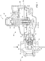
- a regulator 10 includes a valve 30 and an actuator 60.
- the valve 30 includes a valve body 32 having a fluid inlet 34 and a fluid outlet 36 connected by a flow corridor 38.
- the fluid inlet 34 may be connected to a source of fluid, such as a tank (not shown).
- the fluid inlet 34 is connected to a tank of gas, such as a tank of natural gas or a tank of propane.
- a valve plug 40 and a valve seat 42 are disposed in the flow corridor 38, the valve plug 40 and the valve seat 42 cooperating to control fluid flow through the flow corridor.
- the valve plug 40 may be operatively connected to the actuator 60 by an actuating assembly 44.
- the actuating assembly 44 may include a valve stem 46 operatively connected to a lever 48, which is operatively connected to an actuator stem 62.
- the actuator 60 moves the actuator stem 62 in response to pressure variations within the valve 30.
- the actuator stem 62 moves the lever 48, which moves the valve stem 46.
- the valve stem 46 may be directly coupled to, or integrally formed with, the actuator stem 62.
- the actuator 60 includes an actuator housing 64 defining a cavity 66.
- the cavity 66 is divided into a first chamber 68 and a second chamber 70 by a diaphragm 72.
- the diaphragm 72 is secured to the actuator housing at an attachment flange 74.
- a diaphragm plate 76 is operatively attached to the actuator stem 62 and the diaphragm plate 76 supports the diaphragm 72 during movement within the cavity 66.
- the diaphragm plate 76 is disposed between the diaphragm 72 and the second chamber 70.
- a relief plate 78 is slidably attached to the actuator stem 62.
- the relief plate 78 generally moves with the actuator stem 62 in response to pressure changes in the second chamber 70.
- the relief plate 78 is disposed between the diaphragm 72 and the first chamber 68. Said another way, the diaphragm 72 is at least partially disposed between the diaphragm plate 76 and the relief plate 78.
- An actuator spring 80 is disposed within the first chamber 68, and is substantially co-axial with the actuator stem 62.
- the actuator sprig 80 is seated at one end in an actuator spring seat 82 and the relief plate 78 at the other end.
- a relief spring 84 is also disposed within the first chamber 68, and is substantially co-axial with the actuator stem 62.
- the relief spring 84 is disposed between the relief plate 78 and a relief seat 86.
- the relief spring 84 biases the relief plate 78 towards the diaphragm plate 76. However, when fluid pressure in the second chamber 70 exceeds the force generated by the relief spring 84, the relief plate 78 moves away from the diaphragm plate 76, creating a relief passageway for fluid to vent out of the second chamber 70.
- the second chamber 70 is fluidly connected to the flow corridor 38 upstream of the valve seat 42.
- the relief plate 78 moves away from the diaphragm plate 76, which allows fluid to vent out of the valve body 32 and thus, out of a tank (not shown) that may be connected to the valve body 32 to relieve pressure in the valve body 32 and/or in the tank.
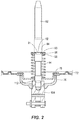
- the relief spring seat 86 may be movably attached to the actuator stem 62 with an attachment device, such as a retaining clip 90.
- the retaining clip 90 may be at least partially disposed in a retaining groove 92 formed on the actuator stem 62.
- the retaining clip 90 may have an inward annular flange 94 and an outward annular flange 96.
- the inward annular flange 94 has a smaller inner diameter than an outer diameter of the actuator stem 62.
- the inner annular flange 94 seats within the retaining groove 92, which has an outer diameter that is slightly smaller than the inner diameter of the inward annular flange 94.
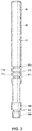
- the retaining clip 90 may have an opening 91 at one side, which allows the retaining clip 90 to expand for removal from the retaining groove 92 and insertion into another retaining groove 92 (see FIG. 3 ).
- the actuator stem 62 may include a plurality of retaining grooves 92a, 92b, 92c, formed in a body 96 of the actuator stem 62.
- the actuator stem 62 may include a spring guide section 98 at one end and a plug flange at another end.
- the spring guide section 98 retains the actuator spring 80 and the relief spring 84.
- the plug flange and a plug groove cooperate secure a plug 104 ( Fig. 2 ) that retains the diaphragm plate 72.
- a plug seat 106 prevents the plug 104 from sliding towards the spring guide section 98.
- a plate attachment flange 108 is separated from the plug seat 106 by an undercut portion 110.
- the plate attachment flange 108 cooperates with an opening 112 in the relief plate 78 to retain the relief plate 78 on the actuator stem 62.
- the grooves 92a, 92b, 92c, in the plurality of grooves 92 are separated from one another by a plurality of retention stops 114a, 114b.
- the retention stops 114a, 114b serve to retain the retaining clip 90 in one of the retaining grooves 92a, 92b, 92c.
- a biasing force generated by the relief spring 84 is changed because a compressed length of the spring is changed.
- FIG. 3 While the embodiment of the actuator stem 62 illustrated in FIG. 3 includes three retaining grooves 92a, 92b, 92c, other embodiments could include more or fewer retaining grooves. For example, other embodiments of the actuator stem 62 may include two, four, five, six, seven, eight, or more retaining grooves.
Landscapes
- Engineering & Computer Science (AREA)
- General Engineering & Computer Science (AREA)
- Mechanical Engineering (AREA)
- Physics & Mathematics (AREA)
- Fluid Mechanics (AREA)
- General Physics & Mathematics (AREA)
- Automation & Control Theory (AREA)
- Safety Valves (AREA)
- Control Of Fluid Pressure (AREA)
- Mechanically-Actuated Valves (AREA)
- Fluid-Driven Valves (AREA)
- Actuator (AREA)
Claims (13)
- Druckentlastungsanordnung für einen Regler (10), wobei die Druckentlastungsanordnung umfasst:eine Betätigungsspindel (62) mit mehreren Entlastungsrückhalterillen (92a-c),eine Entlastungsplatte (78), zur Zusammenwirkung an der Betätigungsspindel (62) befestigt,eine Membranplatte (76), zur Zusammenwirkung an der Betätigungsspindel (62) befestigt,eine Membrane (72), mindestens teilweise zwischen der Entlastungsplatte (78) und der Membranplatte (76) angeordnet,eine Rückhalteklammer (90), in einer der Rückhalterillen (92a-c) angeordnet,einen Entlastungsfedersitz (86), der mit der Rückhalteklammer (90) in einer der mehreren Rückhalterillen (92a-c) abnehmbar an der Betätigungsspindel (62) befestigt ist,eine Entlastungsfeder (84), an der Betätigungsspindel (62) angeordnet, wobei die Entlastungsfeder (84) zwischen dem Entlastungsfedersitz (86) und der Entlastungsplatte (78) angeordnet ist, undeinen Plattenbefestigungsflansch (108) an der Betätigungsspindel (62), wobei der Plattenbefestigungsflansch (108) mit einer Öffnung (112) in der Entlastungsplatte (78) zusammenwirkt, um die Entlastungsplatte (78) gleitend auf der Betätigungsspindel (62) zu halten.
- Druckentlastungsanordnung nach Patentanspruch 1, in der die Rückhalterillen (92a-c) durch eine Mehrzahl von Rückhalterasten (114a-b) voneinander getrennt sind.
- Druckentlastungsanordnung nach irgendeinem der vorangehenden Patentansprüche, in der die Betätigungsspindel (62) einen Federführungsabschnitt (98) zum Halten der Entlastungsfeder (84) umfasst.
- Druckentlastungsanordnung nach irgendeinem der vorangehenden Patentansprüche, außerdem einen Stempel (104) an der Betätigungsspindel (62) angeordnet umfassend, wobei der Stempel (104) die Betätigungsspindel (62) mit der Membranplatte (76) verbindet.
- Druckentlastungsanordnung nach irgendeinem der vorangehenden Patentansprüche, außerdem einen Stempelflansch an der Betätigungsspindel (62) umfassend.
- Druckentlastungsanordnung nach irgendeinem der vorangehenden Patentansprüche, außerdem einen Stempelsitz (106) an der Betätigungsspindel (62) umfassend.
- Druckentlastungsanordnung nach Patentanspruch 6, wenn er von Patentanspruch 5 abhängt, in der der Stempelflansch und der Stempelsitz (106) durch eine Stempelrille voneinander getrennt sind.
- Druckentlastungsanordnung nach Patentanspruch 7, wenn er von Patentanspruch 4 abhängt, in der ein Teil des Stempels (104) in der Stempelrille angeordnet ist.
- Druckentlastungsanordnung nach irgendeinem der vorangehenden Patentansprüche, wenn er von Patentanspruch 6 abhängt, außerdem einen Unterschneidungsbereich (110) an der Betätigungsspindel (62) umfassend, wobei der Unterschneidungsbereich (110) zwischen dem Plattenbefestigungsflansch (108) und dem Stempelsitz (106) angeordnet ist.
- Druckentlastungsanordnung nach irgendeinem der Patentansprüche 2 bis 9, in dem die mehreren Rückhalterillen (92a-c) drei Rückhalterillen umfassen, und die drei Rückhalterillen (92a-c) durch zwei Rückhalterasten (114a, 114b) voneinander getrennt sind.
- Regler (10) für ein Fluidleitungssystem, wobei der Regler umfasst:die Druckentlastungsanordnung nach irgendeinem der vorangehenden Patentansprüche,einen Ventilkörper (32) mit einem Fluideinlass (34) und einem Fluidauslass (36), undeine Betätigungseinheit (60) die durch die Betätigungsspindel (62) zum Zusammenwirken mit einem Ventilstopfen (40) verbunden ist,wobei die Betätigungseinheit (60) den Ventilstopfen (40) innerhalb des Ventilkörpers bewegt, um die Fluidströmung durch den Ventilkörper zu regulieren.
- Regler nach Patentanspruch 11, außerdem eine Betätigungsanordnung (44) umfassend, die den Ventilstopfen (40) zum Zusammenwirken mit der Betätigungseinheit (60) verbindet.
- Regler nach Patentanspruch 12, wobei die Betätigungsanordnung (44) eine Ventilspindel (46) umfasst und vorzugsweise einen Hebel (48), der zum Zusammenwirken mit der Ventilspindel (46) und der Betätigungsspindel (62) verbunden ist.
Applications Claiming Priority (2)
| Application Number | Priority Date | Filing Date | Title |
|---|---|---|---|
| US13/628,761 US8939167B2 (en) | 2012-09-27 | 2012-09-27 | Adjustable fixed pressure relief assembly and regulator comprising same |
| PCT/US2013/061527 WO2014052352A1 (en) | 2012-09-27 | 2013-09-25 | Adjustable fixed pressure relief assembly and regulator comprising same |
Publications (2)
| Publication Number | Publication Date |
|---|---|
| EP2901059A1 EP2901059A1 (de) | 2015-08-05 |
| EP2901059B1 true EP2901059B1 (de) | 2019-11-06 |
Family
ID=49322733
Family Applications (1)
| Application Number | Title | Priority Date | Filing Date |
|---|---|---|---|
| EP13774315.9A Active EP2901059B1 (de) | 2012-09-27 | 2013-09-25 | Einstellbare fixierte druckentlastungsanordnung und regler damit |
Country Status (10)
| Country | Link |
|---|---|
| US (1) | US8939167B2 (de) |
| EP (1) | EP2901059B1 (de) |
| JP (1) | JP6267206B2 (de) |
| CN (2) | CN203549024U (de) |
| AR (1) | AR092696A1 (de) |
| BR (1) | BR112015006698A2 (de) |
| CA (1) | CA2884826C (de) |
| MX (1) | MX362431B (de) |
| RU (1) | RU2659587C2 (de) |
| WO (1) | WO2014052352A1 (de) |
Families Citing this family (10)
| Publication number | Priority date | Publication date | Assignee | Title |
|---|---|---|---|---|
| US9234599B2 (en) * | 2012-09-14 | 2016-01-12 | Emerson Process Management Regulator Technologies, Inc. | Method and apparatus for damping an actuator on a fluid regulator |
| US8939167B2 (en) * | 2012-09-27 | 2015-01-27 | Emerson Process Management Regulator Technologies, Inc. | Adjustable fixed pressure relief assembly and regulator comprising same |
| US9297467B1 (en) * | 2014-01-23 | 2016-03-29 | John O. Goseco | Fluid leak detector apparatus |
| CN107269920A (zh) * | 2017-04-26 | 2017-10-20 | 郑州磨料磨具磨削研究所有限公司 | 一种泄压阀 |
| DE202017104079U1 (de) * | 2017-07-07 | 2017-08-21 | Samson Ag | Stellantrieb für Prozessventile |
| US10337639B2 (en) * | 2017-08-16 | 2019-07-02 | Fisher Controls International Llc | Apparatus to bias a moveable tube towards a seal |
| RO134311A2 (ro) * | 2018-10-10 | 2020-07-30 | Emerson Process Management Regulator Technologies Inc. | Ansamblu de siguranţă cu închidere bruscă pentru furnizarea întreruperii de siguranţă redundantă |
| CN111102365B (zh) * | 2018-10-29 | 2024-08-02 | 艾默生过程管理调节技术公司 | 流体调节器 |
| CN109578794B (zh) * | 2018-11-07 | 2020-06-30 | 远军热能动力科技有限公司 | 一种防护罩 |
| DE102021000069A1 (de) * | 2021-01-11 | 2022-07-14 | Truma Gerätetechnik GmbH & Co. KG | Gasdruckregler |
Citations (1)
| Publication number | Priority date | Publication date | Assignee | Title |
|---|---|---|---|---|
| US4433652A (en) * | 1982-06-11 | 1984-02-28 | Standard Oil Company | Composite valve and process |
Family Cites Families (24)
| Publication number | Priority date | Publication date | Assignee | Title |
|---|---|---|---|---|
| US1259263A (en) * | 1914-09-15 | 1918-03-12 | Frank W Merrick | Valve-motion for explosive-engines. |
| US1435779A (en) * | 1920-06-01 | 1922-11-14 | Wright William Warren | Internal-combustion-engine valve-spring compressor |
| US2037340A (en) * | 1935-10-08 | 1936-04-14 | George R Rich | Composite metal article of manufacture |
| US2351874A (en) * | 1942-05-20 | 1944-06-20 | Parker Appliance Co | Relief valve for fuel tanks |
| US2557187A (en) * | 1948-03-15 | 1951-06-19 | Black Sivalls & Bryson Inc | Pressure regulator |
| US2867234A (en) * | 1951-02-14 | 1959-01-06 | Bastian Blessing Co | Pressure regulator safety valve |
| US2710163A (en) * | 1951-10-23 | 1955-06-07 | Mueller Co | Gas pressure regulator |
| US3273856A (en) * | 1963-12-26 | 1966-09-20 | Trw Inc | Valve stem retainer lock |
| JPS4928270Y1 (de) * | 1967-02-14 | 1974-08-01 | ||
| US3599658A (en) * | 1969-07-28 | 1971-08-17 | American Meter Co | Pressure regulator with internal relief valve |
| US4155433A (en) | 1977-10-04 | 1979-05-22 | P. L. Porter Company | Stroke-limiting stop for positioning device |
| US4265271A (en) | 1979-08-20 | 1981-05-05 | Rosaen Borje O | Relief valve |
| SU1188710A1 (ru) * | 1983-06-15 | 1985-10-30 | Предприятие П/Я Р-6601 | Устройство дл регулировани давлени газа |
| JPS60185009U (ja) * | 1984-05-19 | 1985-12-07 | 本田技研工業株式会社 | オイルリリ−フ弁 |
| US4852531A (en) * | 1988-03-10 | 1989-08-01 | Dynamet Technology Inc. | Titanium poppet valve |
| US5697398A (en) * | 1995-08-08 | 1997-12-16 | Fisher Controls International, Inc. | Fluid pressure regulator with boost tube unit including stem guide and lever retainer |
| US6431205B1 (en) * | 2000-03-13 | 2002-08-13 | Gaap Gas Control Llc | Damper for diaphragm-operated pressure regulating valves |
| US6923202B2 (en) * | 2002-06-01 | 2005-08-02 | Halkey-Roberts Corporation | Modular pressure relief valve |
| ATE511132T1 (de) * | 2007-04-20 | 2011-06-15 | Fisher Controls Int | Einstellbarer scheibenmechanismus für einen gasregulator |
| US8336574B2 (en) * | 2007-04-20 | 2012-12-25 | Fisher Controls International Llc | Pressure averaging sense tube for gas regulator |
| US8256446B2 (en) | 2007-04-23 | 2012-09-04 | Emerson Process Management Regulator Technologies, Inc. | Modular regulator platform |
| JP2011518397A (ja) * | 2008-04-21 | 2011-06-23 | エマーソン プロセス マネージメント レギュレーター テクノロジーズ インコーポレイテッド | 圧力バランストリムを有する圧力負荷供給圧力調整器 |
| US8397743B2 (en) * | 2010-11-08 | 2013-03-19 | Emerson Process Management Regulator Technologies, Inc. | Internal relief valve apparatus for use with fluid regulators |
| US8939167B2 (en) * | 2012-09-27 | 2015-01-27 | Emerson Process Management Regulator Technologies, Inc. | Adjustable fixed pressure relief assembly and regulator comprising same |
-
2012
- 2012-09-27 US US13/628,761 patent/US8939167B2/en active Active
-
2013
- 2013-09-24 CN CN201320722627.9U patent/CN203549024U/zh not_active Withdrawn - After Issue
- 2013-09-24 CN CN201310571229.6A patent/CN103697206B/zh active Active
- 2013-09-25 RU RU2015111839A patent/RU2659587C2/ru active
- 2013-09-25 EP EP13774315.9A patent/EP2901059B1/de active Active
- 2013-09-25 WO PCT/US2013/061527 patent/WO2014052352A1/en not_active Ceased
- 2013-09-25 BR BR112015006698A patent/BR112015006698A2/pt not_active Application Discontinuation
- 2013-09-25 CA CA2884826A patent/CA2884826C/en active Active
- 2013-09-25 JP JP2015534609A patent/JP6267206B2/ja active Active
- 2013-09-25 MX MX2015004049A patent/MX362431B/es active IP Right Grant
- 2013-09-26 AR ARP130103467A patent/AR092696A1/es unknown
Patent Citations (1)
| Publication number | Priority date | Publication date | Assignee | Title |
|---|---|---|---|---|
| US4433652A (en) * | 1982-06-11 | 1984-02-28 | Standard Oil Company | Composite valve and process |
Also Published As
| Publication number | Publication date |
|---|---|
| RU2015111839A (ru) | 2016-11-20 |
| RU2659587C2 (ru) | 2018-07-03 |
| CN103697206B (zh) | 2017-09-12 |
| JP2015534017A (ja) | 2015-11-26 |
| WO2014052352A1 (en) | 2014-04-03 |
| CA2884826A1 (en) | 2014-04-03 |
| CN103697206A (zh) | 2014-04-02 |
| EP2901059A1 (de) | 2015-08-05 |
| MX2015004049A (es) | 2015-07-06 |
| MX362431B (es) | 2019-01-17 |
| US8939167B2 (en) | 2015-01-27 |
| AR092696A1 (es) | 2015-04-29 |
| JP6267206B2 (ja) | 2018-01-24 |
| CN203549024U (zh) | 2014-04-16 |
| BR112015006698A2 (pt) | 2017-07-04 |
| US20140083528A1 (en) | 2014-03-27 |
| CA2884826C (en) | 2021-05-11 |
Similar Documents
| Publication | Publication Date | Title |
|---|---|---|
| EP2901059B1 (de) | Einstellbare fixierte druckentlastungsanordnung und regler damit | |
| EP2689168B1 (de) | Gegendruckregelventil mit ventilpatrone | |
| US11155158B2 (en) | Ventilation flow rate regulator for a pressurised tank of a vehicle | |
| EP2898386B1 (de) | Ausgeglichener regler mit einer einlassdruckmesssonde | |
| US8590858B2 (en) | Anti-gradient cupped seat for pressure regulator | |
| CN105135014A (zh) | 用于负载调节器的内部泄放阀装置 | |
| CN103430118B (zh) | 先导式减压阀 | |
| EP3497533B1 (de) | Ausgeglichener abnehmbarer regler | |
| EP2745181B1 (de) | Fluidregelventil mit entlüftungsventil | |
| CN113661465B (zh) | 具有切断机构的减压阀 | |
| US9599243B1 (en) | Inline relief valve with parabolic piston face | |
| EP3108320B1 (de) | Ausgeglichener regler mit ausgeglichener trimmung mit variablem druckempfindlichem bereich | |
| US9841119B2 (en) | Pilot valve arrangement | |
| EP2895776B1 (de) | Verfahren und vorrichtung zur dämpfung eines stellgliedes in einem flüssigkeitsregler | |
| US9341276B2 (en) | Valve assembly | |
| EP3212975B1 (de) | Absperrrücksetzungsstiftführungsanordnung und sicherheitsabsperrvorrichtung damit | |
| CN114746828A (zh) | 调节器用限流器 | |
| EP3155495B1 (de) | Überdruckventil für einen druckregler und druckregler mit diesem überdruckventil | |
| JP6049184B2 (ja) | 制御バルブ | |
| CN108571609B (zh) | 用于内阀的弹簧座 |
Legal Events
| Date | Code | Title | Description |
|---|---|---|---|
| PUAI | Public reference made under article 153(3) epc to a published international application that has entered the european phase |
Free format text: ORIGINAL CODE: 0009012 |
|
| 17P | Request for examination filed |
Effective date: 20150424 |
|
| AK | Designated contracting states |
Kind code of ref document: A1 Designated state(s): AL AT BE BG CH CY CZ DE DK EE ES FI FR GB GR HR HU IE IS IT LI LT LU LV MC MK MT NL NO PL PT RO RS SE SI SK SM TR |
|
| AX | Request for extension of the european patent |
Extension state: BA ME |
|
| DAX | Request for extension of the european patent (deleted) | ||
| STAA | Information on the status of an ep patent application or granted ep patent |
Free format text: STATUS: EXAMINATION IS IN PROGRESS |
|
| 17Q | First examination report despatched |
Effective date: 20170529 |
|
| REG | Reference to a national code |
Ref country code: DE Ref legal event code: R079 Ref document number: 602013062578 Country of ref document: DE Free format text: PREVIOUS MAIN CLASS: F16K0031126000 Ipc: F16K0031165000 |
|
| GRAP | Despatch of communication of intention to grant a patent |
Free format text: ORIGINAL CODE: EPIDOSNIGR1 |
|
| STAA | Information on the status of an ep patent application or granted ep patent |
Free format text: STATUS: GRANT OF PATENT IS INTENDED |
|
| RIC1 | Information provided on ipc code assigned before grant |
Ipc: F16K 31/165 20060101AFI20190328BHEP Ipc: F16K 17/32 20060101ALI20190328BHEP Ipc: G05D 16/06 20060101ALI20190328BHEP |
|
| INTG | Intention to grant announced |
Effective date: 20190429 |
|
| GRAS | Grant fee paid |
Free format text: ORIGINAL CODE: EPIDOSNIGR3 |
|
| GRAA | (expected) grant |
Free format text: ORIGINAL CODE: 0009210 |
|
| STAA | Information on the status of an ep patent application or granted ep patent |
Free format text: STATUS: THE PATENT HAS BEEN GRANTED |
|
| AK | Designated contracting states |
Kind code of ref document: B1 Designated state(s): AL AT BE BG CH CY CZ DE DK EE ES FI FR GB GR HR HU IE IS IT LI LT LU LV MC MK MT NL NO PL PT RO RS SE SI SK SM TR |
|
| REG | Reference to a national code |
Ref country code: GB Ref legal event code: FG4D |
|
| REG | Reference to a national code |
Ref country code: CH Ref legal event code: EP Ref country code: AT Ref legal event code: REF Ref document number: 1199176 Country of ref document: AT Kind code of ref document: T Effective date: 20191115 |
|
| REG | Reference to a national code |
Ref country code: IE Ref legal event code: FG4D |
|
| REG | Reference to a national code |
Ref country code: DE Ref legal event code: R096 Ref document number: 602013062578 Country of ref document: DE |
|
| REG | Reference to a national code |
Ref country code: NL Ref legal event code: MP Effective date: 20191106 |
|
| REG | Reference to a national code |
Ref country code: LT Ref legal event code: MG4D |
|
| PG25 | Lapsed in a contracting state [announced via postgrant information from national office to epo] |
Ref country code: FI Free format text: LAPSE BECAUSE OF FAILURE TO SUBMIT A TRANSLATION OF THE DESCRIPTION OR TO PAY THE FEE WITHIN THE PRESCRIBED TIME-LIMIT Effective date: 20191106 Ref country code: NL Free format text: LAPSE BECAUSE OF FAILURE TO SUBMIT A TRANSLATION OF THE DESCRIPTION OR TO PAY THE FEE WITHIN THE PRESCRIBED TIME-LIMIT Effective date: 20191106 Ref country code: SE Free format text: LAPSE BECAUSE OF FAILURE TO SUBMIT A TRANSLATION OF THE DESCRIPTION OR TO PAY THE FEE WITHIN THE PRESCRIBED TIME-LIMIT Effective date: 20191106 Ref country code: LV Free format text: LAPSE BECAUSE OF FAILURE TO SUBMIT A TRANSLATION OF THE DESCRIPTION OR TO PAY THE FEE WITHIN THE PRESCRIBED TIME-LIMIT Effective date: 20191106 Ref country code: LT Free format text: LAPSE BECAUSE OF FAILURE TO SUBMIT A TRANSLATION OF THE DESCRIPTION OR TO PAY THE FEE WITHIN THE PRESCRIBED TIME-LIMIT Effective date: 20191106 Ref country code: BG Free format text: LAPSE BECAUSE OF FAILURE TO SUBMIT A TRANSLATION OF THE DESCRIPTION OR TO PAY THE FEE WITHIN THE PRESCRIBED TIME-LIMIT Effective date: 20200206 Ref country code: GR Free format text: LAPSE BECAUSE OF FAILURE TO SUBMIT A TRANSLATION OF THE DESCRIPTION OR TO PAY THE FEE WITHIN THE PRESCRIBED TIME-LIMIT Effective date: 20200207 Ref country code: PL Free format text: LAPSE BECAUSE OF FAILURE TO SUBMIT A TRANSLATION OF THE DESCRIPTION OR TO PAY THE FEE WITHIN THE PRESCRIBED TIME-LIMIT Effective date: 20191106 Ref country code: PT Free format text: LAPSE BECAUSE OF FAILURE TO SUBMIT A TRANSLATION OF THE DESCRIPTION OR TO PAY THE FEE WITHIN THE PRESCRIBED TIME-LIMIT Effective date: 20200306 Ref country code: NO Free format text: LAPSE BECAUSE OF FAILURE TO SUBMIT A TRANSLATION OF THE DESCRIPTION OR TO PAY THE FEE WITHIN THE PRESCRIBED TIME-LIMIT Effective date: 20200206 |
|
| PG25 | Lapsed in a contracting state [announced via postgrant information from national office to epo] |
Ref country code: IS Free format text: LAPSE BECAUSE OF FAILURE TO SUBMIT A TRANSLATION OF THE DESCRIPTION OR TO PAY THE FEE WITHIN THE PRESCRIBED TIME-LIMIT Effective date: 20200306 Ref country code: RS Free format text: LAPSE BECAUSE OF FAILURE TO SUBMIT A TRANSLATION OF THE DESCRIPTION OR TO PAY THE FEE WITHIN THE PRESCRIBED TIME-LIMIT Effective date: 20191106 Ref country code: HR Free format text: LAPSE BECAUSE OF FAILURE TO SUBMIT A TRANSLATION OF THE DESCRIPTION OR TO PAY THE FEE WITHIN THE PRESCRIBED TIME-LIMIT Effective date: 20191106 |
|
| PG25 | Lapsed in a contracting state [announced via postgrant information from national office to epo] |
Ref country code: AL Free format text: LAPSE BECAUSE OF FAILURE TO SUBMIT A TRANSLATION OF THE DESCRIPTION OR TO PAY THE FEE WITHIN THE PRESCRIBED TIME-LIMIT Effective date: 20191106 |
|
| PG25 | Lapsed in a contracting state [announced via postgrant information from national office to epo] |
Ref country code: EE Free format text: LAPSE BECAUSE OF FAILURE TO SUBMIT A TRANSLATION OF THE DESCRIPTION OR TO PAY THE FEE WITHIN THE PRESCRIBED TIME-LIMIT Effective date: 20191106 Ref country code: ES Free format text: LAPSE BECAUSE OF FAILURE TO SUBMIT A TRANSLATION OF THE DESCRIPTION OR TO PAY THE FEE WITHIN THE PRESCRIBED TIME-LIMIT Effective date: 20191106 Ref country code: CZ Free format text: LAPSE BECAUSE OF FAILURE TO SUBMIT A TRANSLATION OF THE DESCRIPTION OR TO PAY THE FEE WITHIN THE PRESCRIBED TIME-LIMIT Effective date: 20191106 Ref country code: RO Free format text: LAPSE BECAUSE OF FAILURE TO SUBMIT A TRANSLATION OF THE DESCRIPTION OR TO PAY THE FEE WITHIN THE PRESCRIBED TIME-LIMIT Effective date: 20191106 Ref country code: DK Free format text: LAPSE BECAUSE OF FAILURE TO SUBMIT A TRANSLATION OF THE DESCRIPTION OR TO PAY THE FEE WITHIN THE PRESCRIBED TIME-LIMIT Effective date: 20191106 |
|
| REG | Reference to a national code |
Ref country code: DE Ref legal event code: R097 Ref document number: 602013062578 Country of ref document: DE |
|
| REG | Reference to a national code |
Ref country code: AT Ref legal event code: MK05 Ref document number: 1199176 Country of ref document: AT Kind code of ref document: T Effective date: 20191106 |
|
| PG25 | Lapsed in a contracting state [announced via postgrant information from national office to epo] |
Ref country code: SK Free format text: LAPSE BECAUSE OF FAILURE TO SUBMIT A TRANSLATION OF THE DESCRIPTION OR TO PAY THE FEE WITHIN THE PRESCRIBED TIME-LIMIT Effective date: 20191106 Ref country code: SM Free format text: LAPSE BECAUSE OF FAILURE TO SUBMIT A TRANSLATION OF THE DESCRIPTION OR TO PAY THE FEE WITHIN THE PRESCRIBED TIME-LIMIT Effective date: 20191106 |
|
| PLBE | No opposition filed within time limit |
Free format text: ORIGINAL CODE: 0009261 |
|
| STAA | Information on the status of an ep patent application or granted ep patent |
Free format text: STATUS: NO OPPOSITION FILED WITHIN TIME LIMIT |
|
| 26N | No opposition filed |
Effective date: 20200807 |
|
| PG25 | Lapsed in a contracting state [announced via postgrant information from national office to epo] |
Ref country code: SI Free format text: LAPSE BECAUSE OF FAILURE TO SUBMIT A TRANSLATION OF THE DESCRIPTION OR TO PAY THE FEE WITHIN THE PRESCRIBED TIME-LIMIT Effective date: 20191106 Ref country code: AT Free format text: LAPSE BECAUSE OF FAILURE TO SUBMIT A TRANSLATION OF THE DESCRIPTION OR TO PAY THE FEE WITHIN THE PRESCRIBED TIME-LIMIT Effective date: 20191106 |
|
| REG | Reference to a national code |
Ref country code: DE Ref legal event code: R119 Ref document number: 602013062578 Country of ref document: DE |
|
| PG25 | Lapsed in a contracting state [announced via postgrant information from national office to epo] |
Ref country code: MC Free format text: LAPSE BECAUSE OF FAILURE TO SUBMIT A TRANSLATION OF THE DESCRIPTION OR TO PAY THE FEE WITHIN THE PRESCRIBED TIME-LIMIT Effective date: 20191106 |
|
| REG | Reference to a national code |
Ref country code: CH Ref legal event code: PL |
|
| GBPC | Gb: european patent ceased through non-payment of renewal fee |
Effective date: 20200925 |
|
| REG | Reference to a national code |
Ref country code: BE Ref legal event code: MM Effective date: 20200930 |
|
| PG25 | Lapsed in a contracting state [announced via postgrant information from national office to epo] |
Ref country code: LU Free format text: LAPSE BECAUSE OF NON-PAYMENT OF DUE FEES Effective date: 20200925 |
|
| PG25 | Lapsed in a contracting state [announced via postgrant information from national office to epo] |
Ref country code: DE Free format text: LAPSE BECAUSE OF NON-PAYMENT OF DUE FEES Effective date: 20210401 |
|
| PG25 | Lapsed in a contracting state [announced via postgrant information from national office to epo] |
Ref country code: IE Free format text: LAPSE BECAUSE OF NON-PAYMENT OF DUE FEES Effective date: 20200925 Ref country code: GB Free format text: LAPSE BECAUSE OF NON-PAYMENT OF DUE FEES Effective date: 20200925 Ref country code: LI Free format text: LAPSE BECAUSE OF NON-PAYMENT OF DUE FEES Effective date: 20200930 Ref country code: BE Free format text: LAPSE BECAUSE OF NON-PAYMENT OF DUE FEES Effective date: 20200930 Ref country code: CH Free format text: LAPSE BECAUSE OF NON-PAYMENT OF DUE FEES Effective date: 20200930 |
|
| PG25 | Lapsed in a contracting state [announced via postgrant information from national office to epo] |
Ref country code: TR Free format text: LAPSE BECAUSE OF FAILURE TO SUBMIT A TRANSLATION OF THE DESCRIPTION OR TO PAY THE FEE WITHIN THE PRESCRIBED TIME-LIMIT Effective date: 20191106 Ref country code: MT Free format text: LAPSE BECAUSE OF FAILURE TO SUBMIT A TRANSLATION OF THE DESCRIPTION OR TO PAY THE FEE WITHIN THE PRESCRIBED TIME-LIMIT Effective date: 20191106 Ref country code: CY Free format text: LAPSE BECAUSE OF FAILURE TO SUBMIT A TRANSLATION OF THE DESCRIPTION OR TO PAY THE FEE WITHIN THE PRESCRIBED TIME-LIMIT Effective date: 20191106 |
|
| PG25 | Lapsed in a contracting state [announced via postgrant information from national office to epo] |
Ref country code: MK Free format text: LAPSE BECAUSE OF FAILURE TO SUBMIT A TRANSLATION OF THE DESCRIPTION OR TO PAY THE FEE WITHIN THE PRESCRIBED TIME-LIMIT Effective date: 20191106 |
|
| P01 | Opt-out of the competence of the unified patent court (upc) registered |
Effective date: 20230526 |
|
| PGFP | Annual fee paid to national office [announced via postgrant information from national office to epo] |
Ref country code: IT Payment date: 20250820 Year of fee payment: 13 |
|
| PGFP | Annual fee paid to national office [announced via postgrant information from national office to epo] |
Ref country code: FR Payment date: 20250820 Year of fee payment: 13 |