EP2901065B1 - Appareil de cathéter à ballonnet pour détection de fuite à haute pression - Google Patents
Appareil de cathéter à ballonnet pour détection de fuite à haute pression Download PDFInfo
- Publication number
- EP2901065B1 EP2901065B1 EP13841836.3A EP13841836A EP2901065B1 EP 2901065 B1 EP2901065 B1 EP 2901065B1 EP 13841836 A EP13841836 A EP 13841836A EP 2901065 B1 EP2901065 B1 EP 2901065B1
- Authority
- EP
- European Patent Office
- Prior art keywords
- inflatable bladder
- rigid end
- bladder
- fluid
- delivery tube
- Prior art date
- Legal status (The legal status is an assumption and is not a legal conclusion. Google has not performed a legal analysis and makes no representation as to the accuracy of the status listed.)
- Active
Links
Images

Classifications
-
- G—PHYSICS
- G01—MEASURING; TESTING
- G01M—TESTING STATIC OR DYNAMIC BALANCE OF MACHINES OR STRUCTURES; TESTING OF STRUCTURES OR APPARATUS, NOT OTHERWISE PROVIDED FOR
- G01M3/00—Investigating fluid-tightness of structures
- G01M3/02—Investigating fluid-tightness of structures by using fluid or vacuum
- G01M3/022—Test plugs for closing off the end of a pipe
-
- G—PHYSICS
- G01—MEASURING; TESTING
- G01M—TESTING STATIC OR DYNAMIC BALANCE OF MACHINES OR STRUCTURES; TESTING OF STRUCTURES OR APPARATUS, NOT OTHERWISE PROVIDED FOR
- G01M3/00—Investigating fluid-tightness of structures
- G01M3/02—Investigating fluid-tightness of structures by using fluid or vacuum
- G01M3/04—Investigating fluid-tightness of structures by using fluid or vacuum by detecting the presence of fluid at the leakage point
- G01M3/20—Investigating fluid-tightness of structures by using fluid or vacuum by detecting the presence of fluid at the leakage point using special tracer materials, e.g. dye, fluorescent material, radioactive material
Definitions
- the present disclosure generally relates to an inlet adapter for use with a fluid testing device, and more specifically, to an inflatable universal inlet adapter configured to form a fluid tight seal with the fluid system under test when the inlet adapter is inflated.
- a fluid gas, liquid or combination of both
- automobiles have several systems which contain and utilize a fluid in their operation including the fuel system, the exhaust system, the heating, cooling and ventilation (HVAC) system, and the hydraulic power steering and brake systems, to name a few.
- HVAC heating, cooling and ventilation
- numerous industrial machines, household HVAC systems, and other devices utilize a fluid to operate.
- fluids include, for example, gases such as air or evaporated system liquid, fuel, hydraulic fluids, manufactured gases and liquids, and many other fluids.
- leaks in fluid systems are very difficult to detect and/or locate because the leak is small or in a location not easily accessible. Accordingly, a variety of methods and devices have been devised to detect leaks in fluid systems.
- the most common leak detectors utilize a visual indicator to locate a leak so that the leak may be repaired.
- Some of the visual indicators include liquid dyes. The visual indicator is dispensed into the fluid system and leaks are detected by locating places on the system where the visual indicator has escaped the system. For instance, a liquid dye will leave a trace of dye at the leak and smoke will billow out through the leak.
- Liquid dyes tend to be most useful for detecting leaks in fluid systems which utilize a liquid and are not so useful for gas systems or systems which must seal vapors created by the system fluid. Nevertheless, liquid leaks are typically easier to detect than gas and vapor leaks because the liquid itself is usually visible.
- Vaporized dyes and smoke are generally most useful for detecting leaks in gas systems and systems which have vapors.
- vaporized dye may be added to the smoke such that a trace of dye is left at the leak as the smoke flows through the leak.
- devices for producing smoke for leak detection comprise a sealed chamber in which smoke is generated by vaporizing a smoke-producing fluid using a heating element. The smoke within the sealed chamber is forced out of the chamber through an outlet port by air pressure from a source of compressed air pumped into the sealed chamber.
- boosted engines with turbochargers or supercharges
- the boost can be 10 PSI to 15 PSI, or in some cases over 20 PSI.
- These types of tiny leaks only make themselves known at high pressures (e.g., 10-20 PSI or higher).
- inlet adapters are typically used with these high pressure diagnostic leak detectors; however, the inlet adapters are typically customized for use with a fluid system having conduits which are of a specific size and configuration.
- the document JPS56110032 A relates to accurate detection even of slight leakage at any place in a sewer pipe joint by opening a vacuum pipe for inspection in a vacant place and thereby reducing pressure in the place.
- a hollow cylindrical body is moved in the direction of an arrow under the condition that mantles are deflated, and when a connecting pipe is positioned at the joint part of sewer pipes, compressed air is supplied from a compressed-air tube to inflate the mantles and thereby the mantles are closely fitted on to the inside wall of the sewer pipe. Thereafter, the pressure in a circular vacant place formed by the outside surface of the connecting pipe, the inside wall of the sewer pipes and the mantles is reduced through the intermediary of the vacuum pipe for inspection.
- the document JP2003004581 relates to a test method capable of easily and effectively testing a water tight performance of a joint section of a ductile cast iron pipe or the like buried in the ground, and provide a device of testing hydraulic pressure used for the test method.
- the test method is provided with an elastic cylinder capable of expanding and shrinking, a nipple fixed to both ends of the elastic cylinder, a phase flange closing a hollow section of the nipple, and a wheel integrally moving these members, and uses the device of testing hydraulic pressure for pipe with a small or medium-sized bore, which has a pipe passing through the flange and pouring fluid into the elastic cylinder.
- the test device is inserted into a pipe to be tested and bonded to the inner surface of the pipe by pouring the fluid into the elastic cylinder and expanding it, and thereby both ends of a section to be tested of the channel of pipe is set in a water tight closed state, and the inside of the pipe at the closed section to be tested is filled with water and pressurized, and then the fluctuation of the pressure is inspected.
- a central hub including valve means is preferably provided.
- An annular sealing element is preferably joined to the flexible casing to effect a seal with the interior wall of a pipe.
- test plug including an expansible bulb adapted to be placed in a pipe, a tube extending through the bulb and provided with two air-charging conduits, one of which opens into the bulb for expanding the same and the other of which opens into the pipe in which the test plug is applied, said two conduits being independently vale controlled.
- the document US2130030 A relates to a pipe plug comprising a center tube having a pair of end fittings spaced from each other and secured to the tube to form a unit, a tubular core having its ends secured to the end fittings, said core being spaced from the center tube to provide a chamber, said tube having a hole communicating with the chamber and said core also having a hole, an elastic sleeve loosely encompassing the core, but having its ends permanently and tightly united with the end fittings, and couplings connected with the center tube to hold the aforesaid unit in place on the tube and to provide for the attachment of a wielding contrivance.
- the document US4354515 A relates to an apparatus for flushing drain pipes is disclosed having an expansible member of resilient material insertable into the pipe to be flushed, a first valve for connecting the expansible member to a source of fluid under pressure for filling and emptying the expansible member and a second valve also connected to the source of fluid under pressure for flushing the obstruction from the pipe.
- the document US6651486 B1 relates to a pressure testing device comprising a connector adapted to engage a gas line containing a gas supply under pressure is provided.
- the pressure testing device includes a measuring device and a compressible pump.
- the measuring device operably communicates with the connector and is responsive to variations in pressure of the gas supply.
- the compressible pump has an input port and an exhaust port. The input port is adapted to receive ambient gases and the exhaust port is adapted to communicate with the measuring device for delivering ambient gas pressure to the measuring device.
- a balloon-type catheter apparatus which is conformable to fit most all intake and exhaust systems to deliver pressure (with or without smoke) to test the fluid integrity of the fluid system.
- the device is configured to be inserted into the canal of the intake or exhaust system and inflated to seal off the fluid system.
- the pressurized smoke is passed through the inflated inlet adapter to test for leaks.
- an adapter according to claim 1 and a method according to claim 12 are provided.
- One embodiment of the present invention includes a universal inlet adapter for a leak detection device using a pressurized detection media for detecting a leak in a fluid system having a fluid duct.
- the universal inlet adapter comprises an inflatable bladder selectively transitional between an inflated configuration and a deflated configuration.
- the inflatable bladder is configured to be engagable with the fluid duct to form a fluid tight seal therebetween as the inflatable bladder transitions from the deflated configuration to the inflated configuration.
- the universal inlet adapter further includes a test fluid delivery tube extending through the inflatable bladder such that the inflatable bladder is disposed radially outward from the test fluid delivery tube, the test fluid delivery tube being fluidly connectable with the leak detection device for delivering the pressurized detection media into the fluid duct for testing.
- a pair of rigid end caps are coupled to the inflatable bladder, each rigid end cap including an insertion portion and a flange portion extending radially outward from the insertion portion, the pair of rigid end caps being coupled to the inflatable bladder such that the insertion portion of each rigid end cap is inserted into a respective one of the opposed ends of the inflatable bladder, each rigid end cap including an internally threaded aperture.
- a pair of locking rings are configured to cooperate with respective ones of the pair of rigid end caps to secure the bladder therebetween, each locking ring being configured to fit over a respective insertion portion of the pair of rigid end caps and abut a respective flange portion of the end caps to secure the inflatable bladder to the pair of rigid end caps.
- the test fluid delivery tube is externally threaded and adapted to engage with the internally threaded aperture of each rigid end cap. The engagement of the pair of rigid end caps to the test fluid delivery tube fixes an axial length of the inlet adapter during inflation.
- the inflatable bladder may define an internal bladder reservoir, and the test fluid delivery tube may traverse through the internal bladder reservoir.
- the inflatable bladder may be conformable to the shape of the fluid duct as the inflatable bladder transitions from the deflated configuration to the inflated configuration.
- the inflatable bladder may define a tubular configuration.
- the test fluid delivery tube may be co-axially aligned with the bladder.
- the test fluid delivery tube is an elongate rigid tube.
- the test fluid delivery tube may define an internal passageway fluidly isolated from the internal bladder reservoir.
- the universal inlet adapter may additionally include an inflation conduit fluidly connected to the inflatable bladder and fluidly connectable to a pressurized fluid source for selectively transitioning the inflatable bladder from the deflated configuration to the inflated configuration.
- a hand pump may be fluidly coupled or connectable to the inflation conduit for delivering fluid into the inflatable bladder for causing the inflatable bladder to transition from the deflated configuration to the inflated configuration.
- a method of testing the fluid integrity of a fluid system having a fluid duct includes providing a leak detection device including an inflatable bladder selectively transitional between an inflated configuration and a deflated configuration, wherein the inflatable bladder is configured to be engagable with the fluid duct to form a fluid tight seal therebetween as the inflatable bladder transitions from the deflated configuration to the inflated configuration, and a test fluid delivery tube extending through the inflatable bladder such that the inflatable bladder is disposed radially outward from the test fluid delivery tube.
- a pair of rigid end caps are coupled to the inflatable bladder, each rigid end cap including an insertion portion and a flange portion extending radially outward from the insertion portion, the pair of rigid end caps being coupled to the inflatable bladder such that the insertion portion of each rigid end cap is inserted into a respective one of the opposed ends of the inflatable bladder, each rigid end cap including an internally threaded aperture.
- a pair of locking rings are configured to cooperate with respective ones of the pair of rigid end caps to secure the bladder therebetween, each locking ring being configured to fit over a respective insertion portion of the pair of rigid end caps and abut a respective flange portion of the end caps to secure the inflatable bladder to the pair of rigid end caps.
- the test fluid delivery tube is externally threaded and adapted to engage with the internally threaded aperture of each rigid end cap.
- the engagement of the pair of rigid end caps to the test fluid delivery tube fixes an axial length of the inlet adapter during inflation.
- the method additionally includes inserting the leak detection device into the fluid duct and inflating the inflatable bladder to create a fluid tight seal between the inflatable bladder and the fluid duct.
- the method further includes directing a test media into the fluid system via the test fluid delivery tube.
- the inserting step may include inserting the leak detection device into the fluid duct such that a majority of the bladder is inserted into the fluid duct.
- the inflating step may include using a hand pump to inflate the inflatable bladder.
- the inflating step may include inflating the bladder to a pressure greater than the pressure of the test media.
- the inflating step and the directing steps may result in the creation of a pressure differential within the fluid duct on opposed sides of the bladder.
- the method may additionally include the step of fluidly connecting the test fluid delivery tube to the test media.
- the method may further comprise the steps of deflating the bladder from the inflated position to the deflated position to break the fluid-tight seal between the bladder, and removing the leak detection device from the fluid duct.
- a universal and inflatable inlet adapter 10 for use with a fluid leak detector.
- the inlet adapter 10 is configured to assume a deflated configuration to define a small profile to facilitate insertion of the inlet adapter 10 into a fluid system 12 for testing. Once inserted, the inlet adapter 10 is selectively transitional from the deflated configuration to an inflated configuration, wherein the inlet adapter 10 expands so as to create a fluid-tight seal between the inlet adapter 10 and the fluid system 12.
- the inlet adapter 10 is further configured to deliver test media 14 (e.g., smoke) into the fluid system 12 for identifying potential leaks within the system 12.
- test media 14 e.g., smoke
- the inflatable inlet adapter 10 is configured to be conformable to the unique size and configuration of a fluid duct 16 (e.g., intake or exhaust) of the fluid system 12 being tested.
- a fluid duct 16 e.g., intake or exhaust
- the degree to which the inlet adapter 10 is inflated typically depends directly on the size of the opening 18 defined by the fluid duct 16.
- the inlet adapter 10 will generally be inflated to a lesser degree for smaller fluid ducts 16, and to a greater degree for larger fluid ducts 16.
- the inflatable portion of the inlet adapter 10 will generally conform to the specific shape of the duct opening 18 to create a strong, fluid-tight seal between the fluid duct 18 and the inlet adapter 10.
- the inlet adapter 10 includes an inflatable bladder 20 selectively transitional between the inflated configuration and the deflated configuration.
- the inflatable bladder 20 defines an internal bladder reservoir 22 which expands as the bladder 20 transitions from the deflated configuration toward the inflated configuration.
- the inflatable bladder 20 is preferably formed from an expandable, resilient and durable material capable of being inserted within fluid systems for testing.
- the material used to form the bladder 20 should have a sufficient thickness which provides strength and durability to the bladder 20 so as to mitigate inadvertent rupturing of the bladder 20, while at the same time allowing the bladder 20 to be flexible enough so as to generally conform to the unique shape of the fluid duct 16 as the bladder 20 transitions to the inflated configuration.
- the exemplary bladder 20 depicted in the Figures is formed from a generally cylindrical sleeve having an opening extending through the sleeve.
- the bladder 20 preferably engages with a pair of rigid end caps 32, 34 at opposed ends of the bladder 20, as will be described in more detail below.
- the universal inlet adapter 10 further includes a test fluid delivery tube 24 extending through the inflatable bladder 20 for delivering the pressurized detection media 14 (e.g., smoke) into the fluid duct 16 for testing.
- the test fluid delivery tube 24 includes a first end portion 26 connectable to the leak detection device to receive a pressurized testing media 14 therefrom, and an opposing second end portion 28 configured to deliver the pressurized test media 14 into the fluid duct 16 for testing.
- the test fluid delivery tube 24 defines an internal passageway fluidly 30 isolated from the internal bladder reservoir 22 and extending between the first and second end portions 26, 28.
- test fluid delivery tube 24 is an elongate rigid tube extending through the bladder reservoir 24, and co-axially aligned with the bladder 20 such that the inflatable bladder 20 is disposed radially outward from the test fluid delivery tube 24.
- the test fluid delivery tube 24 may include a nipple or fluid connector 25 disposed adjacent the first end portion 26 and being fluidly connectable with the testing device for receiving the testing media 14 therefrom.
- the universal inlet adapter 10 may additionally include a pair of rigid end caps 32, 34 connected to the inflatable bladder 20 at opposed end portions of the inflatable bladder 20.
- a first rigid end cap 32 is connected to the test fluid delivery tube 24 adjacent the first end portion 26 thereof and a second rigid end cap 34 is connected to the test fluid delivery tube 24 adjacent the second end portion 28 thereof.
- the end caps 32, 34 include respective insertion portions 31, 33 insertable into the bladder opening at respective ends of the bladder 20.
- Flange portions 35, 37 extend radially outward from respective insertion portions 31, 33 and preferably define a perimeter or diameter that is larger than the perimeter/diameter of the bladder 20 at the end portions.
- the test fluid delivery tube 24 is externally threaded at the first and second end portions 26, 28, while the first and second end caps 32, 34 include apertures which are internally threaded.
- the external threads on the test fluid delivery tube 24 engage with the internal threads formed on the rigid end caps 32, 34 to connect the end caps 32, 34 to the test fluid delivery tube 24.
- the threaded engagement between the test fluid delivery tube 24 and the rigid end caps 32, 34 preferably forms a fluid-tight seal between the test fluid delivery tube 24 and the rigid end caps 32, 24 to allow the bladder 20 to be inflated without fluid leaking through the interface between the delivery tube 24 and the end caps 32, 34.
- a sealant may be used to strengthen the fluid-tight engagement between the delivery tube 24 and the end caps 32, 34.
- a pair of locking rings 36, 38 are used to connect the inflatable bladder 20 to the end caps 32, 34.
- Each locking ring 36, 38 cooperates with one of the pair of rigid end caps 32, 34 to secure the inflatable bladder 20 between the locking rings 32, 34 and the end caps 36, 38.
- the locking rings 36, 38 fit over respective insertion portions 31, 33 of the end caps 32, 34 and may be positioned adjacent to or in abutting relation with the respective flange portion 35, 37 of the end caps 32, 34.
- the locking rings 36, 38 may define an outer diameter that is flush with the outer diameter of the corresponding flange portion 35, 37.
- the locking rings 36, 38 may include smooth inner diameters which force contact at the tips of the barbs formed on the outer diameter of insertion portions 31, 33 to create an air tight seal. As the bladder 20 inflates, the expanding bladder 20 forces and holds the rings 36, 38 in place
- the engagement of the end caps 32, 34 to the delivery tube 24 preferably fixes the axial length of the inlet adapter 10, such that when the bladder 20 is inflated, the bladder 20 expands radially outward, rather than expanding in an axial dimension.
- the universal inlet adapter 10 may additionally include an inflation conduit 40 fluidly connected to the inflatable bladder 20 and fluidly connectable to a pressurized fluid source for selectively transitioning the inflatable bladder 20 from the deflated configuration to the inflated configuration.
- the inflation conduit 40 extends through the first end cap 32 to deliver pressurized fluid from the fluid source into the bladder 20.
- a hand pump 42 may be fluidly coupled or connectable to the inflation conduit 40 for inflating the bladder 20.
- the hand pump 42 includes a pumping mechanism 44 and a pump conduit 46 for delivering pressurized fluid (e.g., air) into the bladder reservoir 22.
- the hand pump 42 may also include a release valve 45 for releasing fluid from the bladder 20 during deflation thereof.
- the exemplary embodiment includes a hand pump 42 for inflating the bladder 20, those skilled in the art will appreciate that an electrical pump may also be used for inflating the bladder 20.
- the exemplary embodiment includes rigid end caps 32, 34, it is contemplated that other embodiments of the inlet adapter 10 may not include rigid end caps 32, 34.
- the bladder 20 may be coupled directly to the delivery tube 24, and may include an inflation port integrated into the bladder 20 for inflation.
- other embodiments may include a hybrid design wherein a single rigid end cap is used at one end of the bladder 20, while the opposing end of the bladder 20 is formed without an end cap.
- the inlet adapter 10 With the basic structural features of the inlet adapter 10 described above, the following discussion focuses on use of the inlet adapter 10 for testing the fluid integrity of the fluid system 12. With the bladder 20 in the deflated configuration, the inlet adapter 10 is inserted into the duct opening 18 such that a majority of the bladder 20 is inserted into the fluid duct 16. In this regard, a sufficient amount of the bladder 20 is inserted into the duct 16 so as to allow the bladder 20 to create a fluid tight seal between the bladder 20 and the inner surface 48 of the duct 16.
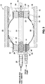
- the inflatable bladder 20 is then inflated to create a fluid tight seal between the inflatable bladder 20 and the inner surface 48 of the fluid duct 16.
- the bladder 20 begins to conform to, or assume the shape of the inner surface 48 of the bladder 20.
- the pressure within the bladder 20 shown in Figure 3 has caused the bladder 20 to engage with the inner surface 48 and to define a flattened region 50 that has assumed the shape of the inner surface 48.
- inflation of the bladder 20 may be achieved through the use of a hand pump 42, or an electrical pump, or via other inflation means known by those skilled in the art.
- the bladder 20 is inflated to an internal pressure which is greater than the testing pressure so as to anchor the bladder 20 firmly within the fluid duct 16 during testing.
- the method further includes directing the pressurized test media 14 into the fluid system 12 via the test fluid delivery tube 24.
- the pressurized test media 14 may be directed into the fluid system 12 by connecting the test fluid delivery tube 24 to testing device.
- a pressure differential may be created within the fluid duct 16 on opposed sides of the bladder 20.
- the pressure within the fluid duct 16 on the downstream side of the bladder 20 e.g., the side to which the pressurized media 14 is emitted
- the pressure within the fluid duct 16 on the opposed side of the bladder 20 is greater than the pressure within the fluid duct 16 on the opposed side of the bladder 20.
- the fluid-tight seal between the bladder 20 and the duct 16 allows the creation of the pressure differential for conducting the fluid integrity testing.
- the fluid integrity testing may be conducted at various pressures, preferably in the range of 0.5-20 PSI, although those skilled in the art will recognize that tests performed at pressures outside of exemplary pressure range may also be conducted without departing from the spirit and scope of the present invention. Elevated testing pressures (i.e., 10-20 PSI) are preferable for boosted engines (with turbochargers or superchargers), wherein the leaks may only be detectable at such high pressures.
- the bladder 20 may be transitioned from the inflated position to the deflated position to break the fluid-tight seal between the bladder 20 and the fluid duct 16, and to facilitate removal of the inlet adapter 10 from the fluid duct 16.
Landscapes
- Physics & Mathematics (AREA)
- General Physics & Mathematics (AREA)
- Examining Or Testing Airtightness (AREA)
Claims (13)
- Adaptateur d'entrée universel (10) pour un dispositif de détection de fuite utilisant un milieu de détection sous pression pour détecter une fuite dans un système de fluide, le système de fluide ayant un conduit de fluide, l'adaptateur d'entrée universel comprenant :une vessie gonflable (20) ayant des extrémités opposées et étant sélectivement en transition entre une configuration gonflée et une configuration dégonflée, la vessie gonflable (20) étant conçue pour pouvoir venir en prise avec le conduit de fluide pour former un joint étanche aux fluides entre eux lorsque la vessie gonflable (20) passe de la configuration dégonflée à la configuration gonflée ;un tube de distribution de fluide de test (24) s'étendant à travers la vessie gonflable (20) de sorte que la vessie gonflable (20) soit disposée radialement vers l'extérieur du tube de distribution de fluide de test (24), le tube de distribution de fluide de test (24) pouvant être en communication fluidique avec le dispositif de détection de fuite pour distribuer le milieu de détection sous pression dans le conduit de fluide à des fins de test ;caractérisé par une paire de capuchons d'extrémité rigides (32, 34) accouplés à la vessie gonflable (20), chaque capuchon d'extrémité rigide (32, 34) comprenant une partie d'insertion (31, 33) et une partie de bride (35, 37) s'étendant radialement vers l'extérieur depuis la partie d'insertion (31, 33), la paire de capuchons d'extrémité rigides (32, 34) étant accouplés à la vessie gonflable (20) de sorte que la partie d'insertion (31, 33) de chaque capuchon d'extrémité rigide (32, 34) soit insérée dans une extrémité respective des extrémités opposées de la vessie gonflable (20), chaque capuchon d'extrémité rigide (32, 34) comprenant une ouverture filetée intérieurement ; etune paire d'anneaux de verrouillage (36, 38) conçus pour coopérer avec des capuchons d'extrémité rigides respectifs de la paire de capuchons d'extrémité rigides (32, 34) pour fixer la vessie (20) entre eux, chaque anneau de verrouillage (36, 38) étant conçu pour s'adapter sur une partie d'insertion (31, 33) respective de la paire de capuchons d'extrémité rigides (32, 34) et pour venir en butée contre une partie de bride (35, 37) respective des capuchons d'extrémité pour fixer la vessie gonflable (20) à la paire de capuchons d'extrémité rigides (32, 34),le tube de distribution de fluide de test (24) étant fileté à l'extérieur et conçu pour venir en prise avec l'ouverture filetée à l'intérieur de chaque capuchon d'extrémité rigide (32, 34) ; etla mise en prise de la paire de capuchons d'extrémité rigides (32, 34) avec le tube de distribution de fluide de test (24) fixant une longueur axiale de l'adaptateur d'entrée pendant le gonflage.
- Adaptateur d'entrée universel selon la revendication 1, la vessie gonflable (20) définissant un réservoir de vessie interne (22), le tube de distribution de fluide de test (24) traversant le réservoir de vessie interne (22).
- Adaptateur d'entrée universel selon la revendication 1, la vessie gonflable (20) pouvant prendre la forme du conduit de fluide lorsque la vessie gonflable (20) passe de la configuration dégonflée à la configuration gonflée.
- Adaptateur d'entrée universel selon la revendication 1, la vessie gonflable (20) définissant une configuration tubulaire.
- Adaptateur d'entrée universel selon la revendication 4, le tube de distribution de fluide de test (24) étant aligné coaxialement avec la vessie (20).
- Adaptateur d'entrée universel selon la revendication 1, le tube de distribution de fluide de test (24) étant un tube rigide allongé.
- Adaptateur d'entrée universel selon la revendication 1, comprenant en outre un conduit de gonflage (40) en communication fluidique avec la vessie gonflable (20) et pouvant être en communication fluidique avec une source de fluide sous pression pour faire passer sélectivement la vessie gonflable (20) de la configuration dégonflée à la configuration gonflée.
- Adaptateur d'entrée universel selon la revendication 7, comprenant en outre une pompe manuelle (42) accouplée fluidiquement au conduit de gonflage (40) pour distribuer du fluide dans la vessie gonflable (20) pour amener la vessie gonflable (20) à passer de la configuration dégonflée à la configuration gonflée.
- Adaptateur d'entrée universel selon la revendication 1, la paire de capuchons d'extrémité rigides (32, 34) comprenant un premier capuchon d'extrémité rigide (32) et un second capuchon d'extrémité rigide (34), le premier capuchon d'extrémité rigide (32) étant connecté au tube de distribution de fluide de test (24) et au conduit de gonflage (40), le second capuchon d'extrémité rigide (34) étant connecté au tube de distribution de fluide de test (24).
- Adaptateur d'entrée universel selon la revendication 1, la paire de capuchons d'extrémité rigides (32, 34) et le tube de distribution de fluide de test (24) pouvant venir en prise par filetage.
- Adaptateur d'entrée universel selon la revendication 1, le tube de distribution de fluide de test (24) définissant un passage interne isolé fluidiquement du réservoir de vessie interne (22).
- Procédé pour tester l'intégrité aux fluides d'un système de fluides ayant un conduit de fluide, le procédé comprenant les étapes consistant à :insérer un dispositif de détection de fuite dans le conduit de fluide, le dispositif de détection de fuite comprenant :une vessie gonflable (24) ayant des extrémités opposées et étant sélectivement en transition entre une configuration gonflée et une configuration dégonflée, la vessie gonflable étant conçue pour pouvoir venir en prise avec le conduit de fluide pour former un joint étanche aux fluides entre eux lorsque la vessie gonflable passe de la configuration dégonflée à la configuration gonflée ;un tube de distribution de fluide de test (24) s'étendant à travers la vessie gonflable (20) de sorte que la vessie gonflable (20) soit disposée radialement vers l'extérieur à partir du tube de distribution de fluide de test (24) ;caractérisé par une paire de capuchons d'extrémité rigides (32, 34) accouplés à la vessie gonflable, chaque capuchon d'extrémité rigide (32, 34) comprenant une partie d'insertion (31, 33) et une partie de bride (35, 37) s'étendant radialement vers l'extérieur depuis la partie d'insertion (31, 33), la paire de capuchons d'extrémité rigides (32, 34) étant accouplés à la vessie gonflable (20) de sorte que la partie d'insertion (31, 33) de chaque capuchon d'extrémité rigide (32, 34) soit insérée dans une extrémité respective des extrémités opposées de la vessie gonflable (20), chaque capuchon d'extrémité rigide (32, 34) comprenant une ouverture filetée intérieurement ; etune paire d'anneaux de verrouillage (36, 38) conçus pour coopérer avec des capuchons d'extrémité rigides respectifs de la paire de capuchons d'extrémité rigides (32, 34) pour fixer la vessie (20) entre eux, chaque anneau de verrouillage (36, 38) étant conçu pour s'adapter sur une partie d'insertion respective de la paire de capuchons d'extrémité rigides et pour buter contre une partie de bride (35, 37) respective des capuchons d'extrémité pour fixer la vessie gonflable à la paire de capuchons d'extrémité rigides (32, 34),le tube de distribution de liquide de test (24) étant fileté à l'extérieur et conçu pour venir en prise avec l'ouverture filetée à l'intérieur de chaque capuchon d'extrémité rigide (32, 34) ; etla mise en prise de la paire de capuchons d'extrémité rigides (32, 34) avec le tube de distribution de fluide de test (24) fixant une longueur axiale de l'adaptateur d'entrée pendant le gonflage ;gonfler la vessie gonflable (20) pour créer un joint étanche aux fluides entre la vessie gonflable (20) et le conduit de fluide ; etdiriger un milieu de test (14) dans le système de fluide par l'intermédiaire du tube de distribution de fluide de test (24) pour tester l'intégrité aux fluides du système de fluide.
- Procédé selon la revendication 12, l'étape de gonflage et l'étape de direction entraînant la création d'une différence de pression dans le conduit de fluide sur les côtés opposés de la vessie (20).
Applications Claiming Priority (3)
| Application Number | Priority Date | Filing Date | Title |
|---|---|---|---|
| US201261706690P | 2012-09-27 | 2012-09-27 | |
| US13/926,919 US9417153B2 (en) | 2012-09-27 | 2013-06-25 | Balloon catheter apparatus for high pressure leak detection |
| PCT/US2013/060732 WO2014052170A1 (fr) | 2012-09-27 | 2013-09-19 | Appareil de cathéter à ballonnet pour détection de fuite à haute pression |
Publications (3)
| Publication Number | Publication Date |
|---|---|
| EP2901065A1 EP2901065A1 (fr) | 2015-08-05 |
| EP2901065A4 EP2901065A4 (fr) | 2016-05-18 |
| EP2901065B1 true EP2901065B1 (fr) | 2021-03-03 |
Family
ID=50337551
Family Applications (1)
| Application Number | Title | Priority Date | Filing Date |
|---|---|---|---|
| EP13841836.3A Active EP2901065B1 (fr) | 2012-09-27 | 2013-09-19 | Appareil de cathéter à ballonnet pour détection de fuite à haute pression |
Country Status (5)
| Country | Link |
|---|---|
| US (2) | US9417153B2 (fr) |
| EP (1) | EP2901065B1 (fr) |
| JP (1) | JP2015535934A (fr) |
| CA (1) | CA2886075C (fr) |
| WO (1) | WO2014052170A1 (fr) |
Families Citing this family (25)
| Publication number | Priority date | Publication date | Assignee | Title |
|---|---|---|---|---|
| US9417153B2 (en) | 2012-09-27 | 2016-08-16 | Redline Detection, Llc | Balloon catheter apparatus for high pressure leak detection |
| US9869603B2 (en) | 2012-09-27 | 2018-01-16 | Redline Detection, Llc | Balloon catheter apparatus for internal combustion engine component leak detection and high pressure leak detection |
| US10030568B2 (en) * | 2014-03-27 | 2018-07-24 | Dwight Eric STORY | Exhaust system integrity tester |
| EP3268655B1 (fr) * | 2015-03-09 | 2022-10-19 | Redline Detection, LLC | Appareil de cathéter à ballonnet pour détection de fuite de composant de moteur à combustion interne et détection de fuite à haute pression |
| US9933326B2 (en) | 2015-07-22 | 2018-04-03 | Redline Detection, Llc | System and method for detecting microscopic leaks |
| CN108291851A (zh) | 2015-09-13 | 2018-07-17 | 精适分销有限公司 | 烟检测机 |
| KR101956147B1 (ko) * | 2015-12-16 | 2019-03-12 | 류원하 | 파이프 누설시험용 밀폐장치 |
| WO2017142886A1 (fr) * | 2016-02-16 | 2017-08-24 | Cherne Industries, Inc. | Bouchon d'essai haute-pression |
| CN112816160B (zh) | 2016-02-18 | 2023-10-24 | 太阳能安吉科技有限公司 | 用于气密性测试的方法和设备、通风塞 |
| US10578511B2 (en) * | 2016-09-16 | 2020-03-03 | Cps Products, Inc. | Flexible universal bladder tool for detecting leaks in a closed fluid system |
| US11268875B2 (en) | 2016-11-22 | 2022-03-08 | Redline Detection, Llc | Method and apparatus for fluid leak detection |
| CN109372581B (zh) * | 2018-12-14 | 2023-11-14 | 山东科技大学 | 一种顶板岩层水平挤压力监测装置及使用方法 |
| CN110146231B (zh) * | 2019-06-17 | 2020-09-29 | 蚌埠兴创电子科技有限公司 | 一种节约氦气的氦质谱检测装置 |
| CN110252555B (zh) * | 2019-07-19 | 2024-03-29 | 江苏耀坤液压股份有限公司 | 一种液压油管喷涂吊具 |
| US11371906B1 (en) * | 2019-10-07 | 2022-06-28 | Precision Diving Equipment Llc | One-way valve tester and method of using same |
| CN111306319B (zh) * | 2020-04-08 | 2024-10-25 | 成都市笑脸科技有限公司 | 一种外膨胀式柔性压力阀 |
| US11530960B1 (en) * | 2020-10-27 | 2022-12-20 | Plumbing Diagnostics Corp. | Method of testing for leaks in the piping system of a building |
| JP7432491B2 (ja) * | 2020-12-08 | 2024-02-16 | 株式会社ブリヂストン | サイホン排水システムの検査方法、治具 |
| US11820343B2 (en) | 2021-05-04 | 2023-11-21 | Westinghouse Air Brake Technologies Corporation | System and method for detection of multi-vehicle system separation |
| CN113187429A (zh) * | 2021-06-16 | 2021-07-30 | 邹城兖矿泰德工贸有限公司 | 矿用封孔囊袋 |
| US12420641B2 (en) | 2021-06-25 | 2025-09-23 | Redline Detection, Llc | Leak detection system for vehicle battery environment and related methodology |
| US11804118B2 (en) * | 2022-03-01 | 2023-10-31 | Honeywell International Inc. | Aspirating smoke detector discreet sample point |
| CN114923060A (zh) * | 2022-05-18 | 2022-08-19 | 中国葛洲坝集团机电建设有限公司 | 一种用于管道的封堵装置及封堵装置的装卸方法 |
| CN116296095B (zh) * | 2023-02-24 | 2023-11-14 | 苏州苏大卫生与环境技术研究所有限公司 | 一种医用防回流送水接头的检测装置 |
| CN118464335B (zh) * | 2024-06-13 | 2025-01-24 | 山东睿海智能装备科技有限公司 | 一种多功能阀门动态检测设备 |
Citations (13)
| Publication number | Priority date | Publication date | Assignee | Title |
|---|---|---|---|---|
| GB190913611A (en) * | 1909-06-10 | 1910-05-05 | George Davis | Improvements in Drain Stoppers. |
| US1506418A (en) * | 1923-02-26 | 1924-08-26 | Ez Mfg Co | Test plug |
| US2130030A (en) * | 1936-08-06 | 1938-09-13 | James F Richardson | Pipe plug |
| US4354515A (en) * | 1980-11-10 | 1982-10-19 | Sutherland Rabion C | Drain pipe flushing apparatus |
| US4550751A (en) * | 1981-10-28 | 1985-11-05 | Misuzu Machineries & Engineering Ltd. | Ballast exhaust pipe closing appliance for a ship |
| US4750525A (en) * | 1985-04-15 | 1988-06-14 | Vaughan Daniel J | End closure for flexible plastic tubes |
| WO2000047928A1 (fr) * | 1999-02-11 | 2000-08-17 | Glynwed Pipe Systems Limited | Appareil permettant d'arreter l'ecoulement dans un tuyau |
| GB2361283A (en) * | 2000-03-31 | 2001-10-17 | Martyn James Smith | Inflatable annular seal for closing off a pipe |
| US20020083988A1 (en) * | 2001-01-04 | 2002-07-04 | Lundman Philip L. | Pipe sealing apparatus |
| US6651486B1 (en) * | 2000-09-29 | 2003-11-25 | Basic Resources, Inc. | Standup pressure testing device and method |
| EP2180228A2 (fr) * | 2008-10-24 | 2010-04-28 | Francisco Javier Lardies Sobreviela | Dispositif d'obturation pneumatique haute pression pour tuyaux |
| WO2011147021A1 (fr) * | 2010-05-28 | 2011-12-01 | Peter Karl Krahn | Appareil à vessie extensible en polymère, pour canalisations et puits sous-marins |
| US8246052B1 (en) * | 2006-10-31 | 2012-08-21 | Ge Oil & Gas Esp, Inc. | Bladder containment mechanism |
Family Cites Families (88)
| Publication number | Priority date | Publication date | Assignee | Title |
|---|---|---|---|---|
| US1510212A (en) | 1922-11-29 | 1924-09-30 | Bois Rhesa G Du | Device for opening stopped drainpipes |
| US1710439A (en) * | 1926-09-22 | 1929-04-23 | Taylor Orson | Pipe-pressure-testing plug |
| US2192155A (en) * | 1937-04-02 | 1940-02-27 | Elmer F Schuldt | Method of and means for locating leaks in a gas main or the like |
| US2273984A (en) | 1940-02-19 | 1942-02-24 | William D Osborn | Safety plug and bypass |
| US2299116A (en) * | 1941-05-05 | 1942-10-20 | Svirsky Bennett | Expansible plugs for conduits |
| US2764243A (en) | 1952-04-14 | 1956-09-25 | John S Page | Well packer |
| US2753876A (en) * | 1955-03-15 | 1956-07-10 | Midwest Rubber Company | Drain plug valve flushing device |
| US3024200A (en) | 1959-01-26 | 1962-03-06 | Collins Radio Co | Smoke generator |
| US3075535A (en) | 1961-05-29 | 1963-01-29 | Lasting Walter | Apparatus for flushing extraneous matter from clogged drain pipes |
| CH401788A (de) | 1961-11-02 | 1965-10-31 | Seuthe Eberhard | Vorrichtung zum Erzeugen von Dampf, insbesondere zur Anwendung bei einem Spielzeug |
| US3129726A (en) * | 1962-04-06 | 1964-04-21 | John F Moore | Test plug for fluid systems |
| US3431946A (en) * | 1965-11-19 | 1969-03-11 | Willard A Sawyer | Inflatable pipe plug |
| US3431945A (en) * | 1966-05-23 | 1969-03-11 | Hubert A Robillard | Plumber's pneumatic plug |
| US3583239A (en) * | 1969-10-10 | 1971-06-08 | Nasa | Tube sealing device |
| US3837214A (en) * | 1973-01-30 | 1974-09-24 | Halliburton Co | Self-propelled pipeline plug |
| US3870085A (en) | 1973-06-20 | 1975-03-11 | Michael Schneider | Expansible plugs for sewer pipes |
| JPS56110032A (en) | 1980-02-05 | 1981-09-01 | Nippon Kanken Kogyo Kk | Inspecting method for water leakage from buried pipe |
| US4352515A (en) | 1980-07-07 | 1982-10-05 | Schumacher John B | Pin-actuated rotatable ram bar apparatus and carrier adapter |
| US4373767A (en) | 1980-09-22 | 1983-02-15 | Cairns James L | Underwater coaxial connector |
| US4373381A (en) * | 1981-01-29 | 1983-02-15 | Leon Kulp | Manhole leakage indicator and method for using |
| US4460019A (en) * | 1981-06-18 | 1984-07-17 | Condon Technologies, Inc. | Sewer and drain plug |
| US4524607A (en) | 1982-04-05 | 1985-06-25 | Science Applications International Corporation | System and method for locating leaking tubes |
| JPS59126223A (ja) * | 1983-01-07 | 1984-07-20 | Showa Kiki Kogyo Kk | ガソリンスタンドにおける地下タンクの配管耐圧検査機構 |
| JPS59138935A (ja) * | 1983-01-31 | 1984-08-09 | Nippon Enjiniyaa Service Kk | 配管検査装置 |
| US4608858A (en) * | 1984-11-05 | 1986-09-02 | Mckinnon Robert M | Pneumatic test plug |
| US4764660A (en) | 1985-10-22 | 1988-08-16 | The United States Of America As Represented By The Secretary Of The Navy | Electric smoke generator |
| US4614206A (en) * | 1985-11-14 | 1986-09-30 | Cherne Industries, Inc. | Expansible pneumatic plug device |
| US4818843A (en) | 1988-02-12 | 1989-04-04 | Edmund Swiatosz | Smoke generator |
| US4905931A (en) | 1988-02-18 | 1990-03-06 | The Boeing Company | Arc suppression around fasteners |
| US4887931A (en) * | 1989-02-16 | 1989-12-19 | Baker Hughes Incorporated | Method and apparatus for towing subsea pipeline sections |
| US5022435A (en) | 1990-08-24 | 1991-06-11 | Jaw Shiunn Tsay | Gas regulator with safety device |
| US5353842A (en) * | 1992-02-20 | 1994-10-11 | Lundman Philip L | Inflatable plug for use in plugging a large diameter pipe |
| US5328152A (en) | 1992-06-29 | 1994-07-12 | Bruce Industries, Inc. | Fluid control valve unit |
| US5390738A (en) | 1992-11-25 | 1995-02-21 | Dowell Schlumberger Incorporated | Inflatable packer inner bladder retention and seal |
| DE9310532U1 (de) * | 1993-07-15 | 1993-09-02 | Göhner, Gilbert, Dipl.-Ing. (FH), 3180 Wolfsburg | Dampfeinblasvorrichtung |
| JP2544888B2 (ja) * | 1993-07-28 | 1996-10-16 | 株式会社湘南合成樹脂製作所 | 管ライニング材の検査方法 |
| AUPM307693A0 (en) * | 1993-12-21 | 1994-01-20 | Uponor N.V. | Expandable plug |
| US5425266A (en) * | 1994-01-25 | 1995-06-20 | Envirotest Systems Corp. | Apparatus and method for non-intrusive testing of motor vehicle evaporative fuel systems |
| US5647054A (en) | 1994-12-09 | 1997-07-08 | Pitsco, Inc. | Smoke generator tube |
| US5735955A (en) | 1995-04-08 | 1998-04-07 | General Chemical Company | Apparatus for generating and dispersing foam herbicide within a sewer |
| US6131441A (en) * | 1996-12-02 | 2000-10-17 | Berube; Guy | Apparatus and method for isolating or testing a pipe segment |
| US5771937A (en) * | 1996-12-13 | 1998-06-30 | Mcp Industries, Inc. | Pipe plug and method |
| US5859363A (en) | 1997-07-01 | 1999-01-12 | Gouge; Larry Michael | Device and method for smoke testing of gas furnace heat exchangers |
| US6314795B1 (en) | 1997-07-22 | 2001-11-13 | Ferret Technology Limited | Leak tracing |
| GB9719101D0 (en) * | 1997-09-10 | 1997-11-12 | British Gas Plc | Pipe leak detection |
| CA2216476C (fr) | 1997-09-25 | 2003-07-22 | Norton Marcus Loblick | Appareil produisant de la fumee |
| US5922944A (en) | 1998-02-09 | 1999-07-13 | Pieroni; Kenneth Alan | Smoke producing apparatus for detecting leaks in a fluid system |
| JP3609602B2 (ja) * | 1998-02-25 | 2005-01-12 | 東京瓦斯株式会社 | 気密試験治具 |
| CA2238301C (fr) | 1998-05-22 | 2006-01-24 | Vanberg, Gerald | Appareil pour generer de la fumee |
| US6116286A (en) * | 1998-07-15 | 2000-09-12 | Hooper; Robert A. | Pneumatic pipe plug |
| US6267001B1 (en) * | 1998-09-25 | 2001-07-31 | E Ticket Enterprises, Llc | Test plug |
| GB9900471D0 (en) | 1999-01-09 | 1999-03-03 | Bedwell Leslie W | Apparatus and method for leak detection |
| US6175987B1 (en) | 1999-01-13 | 2001-01-23 | Russell Harvey | Paint brush holder |
| US6361752B1 (en) | 1999-05-19 | 2002-03-26 | S. C. Johnson & Son, Inc. | Apparatus for volatilizing and dispensing a chemical into a room environment |
| US6536260B2 (en) * | 1999-06-24 | 2003-03-25 | Datascope Investment Corp. | Balloon catheter leak detection method and apparatus |
| US6526808B1 (en) | 1999-07-07 | 2003-03-04 | Star Envirotech, Inc. | Smoke and clean air generating machine for detecting presence and location of leaks in a fluid system |
| CA2279147C (fr) | 1999-07-29 | 2003-02-18 | Graminia Developments Ltd. | Liquide pour produire une vapeur de marquage, une methode pour produire cette vapeur de marquage et une methode d'inspection a l'aide de celle-ci |
| US6439031B1 (en) | 1999-08-30 | 2002-08-27 | Star Envirotech, Inc. | Method for detecting leaks in a fluid system |
| JP4457243B2 (ja) * | 2000-06-26 | 2010-04-28 | 株式会社サンフロイント | 埋設配管欠陥箇所検出装置 |
| US6336482B1 (en) | 2000-10-31 | 2002-01-08 | Pilot Industries, Inc. | Automotive fuel tank fill assembly |
| JP2002168391A (ja) * | 2000-11-29 | 2002-06-14 | Osaka Gas Co Ltd | 流体遮断用バッグ |
| US6481465B1 (en) * | 2001-01-23 | 2002-11-19 | Gerard G. Warmerdam | Compressed-ring pneumatic pipe plug |
| US6389613B1 (en) | 2001-03-14 | 2002-05-21 | James Comas | Pressure flush control system |
| JP3817622B2 (ja) | 2001-03-30 | 2006-09-06 | 株式会社栗本鐵工所 | 中小口径管用水圧試験器 |
| US6523394B2 (en) | 2001-04-18 | 2003-02-25 | The United States Of America As Represented By The Secretary Of The Navy | Leak test fixture |
| US6502603B2 (en) * | 2001-05-16 | 2003-01-07 | John B. Lane, Jr. | Test plug handle |
| US20030047881A1 (en) | 2001-09-13 | 2003-03-13 | Worm Steven Lee | Sealing system and pressure chamber assembly including the same |
| US6899138B2 (en) | 2002-12-09 | 2005-05-31 | Philip L. Lundman | Flexible emergency gas pipeline plug |
| SI21516A (sl) * | 2003-06-11 | 2004-12-31 | SAVATECH družba za proizvodnjo gumenotehničnih proizvodov | Pnevmatski zaporni čep za cevovode, zlasti plinovode |
| FR2856456B1 (fr) * | 2003-06-20 | 2005-09-09 | Schlumberger Services Petrol | Dispositif d'etancheite pour l'obturation temporaire d'un puits ou d'une canalisation. |
| CA2438448C (fr) | 2003-08-27 | 2008-11-18 | Quality Fabricating & Machining Ltd. | Detecteur de fuites |
| JP2005233314A (ja) * | 2004-02-19 | 2005-09-02 | Tokai Rubber Ind Ltd | 配管の密栓方法 |
| FR2875286B1 (fr) * | 2004-09-13 | 2008-04-25 | Saltel Ind Soc Par Actions Sim | Dispositif d'etancheite servant a obturer un puits ou une canalisation |
| US7305176B1 (en) | 2004-10-28 | 2007-12-04 | Redline Detection, Llc | Method and device for detecting leaks using smoke |
| US7013926B1 (en) * | 2004-11-22 | 2006-03-21 | Randy Storey | Plumbing leak testing apparatus |
| US7650805B2 (en) | 2005-10-11 | 2010-01-26 | Millipore Corporation | Integrity testable multilayered filter device |
| US7556072B2 (en) * | 2007-04-10 | 2009-07-07 | Koch Jr Edward | Log splitting apparatus and method for its use |
| US20100163254A1 (en) * | 2007-06-07 | 2010-07-01 | Saltel Industries | Device For Sealing Off A Well And A Pipe And A Fitting Method |
| JP2009243895A (ja) * | 2008-03-28 | 2009-10-22 | Taisei Corp | 密閉試験装置及び管体接合部の密閉試験方法 |
| US8375770B2 (en) | 2008-04-21 | 2013-02-19 | Redline Detection, Llc | Engine leak detector and leak detection method |
| JP2009270969A (ja) * | 2008-05-08 | 2009-11-19 | Fuji Electric Holdings Co Ltd | 漏洩検査用治具 |
| US20090315326A1 (en) | 2008-06-24 | 2009-12-24 | Pieroni Kenneth A | Universal inlet adapter |
| US7597118B1 (en) * | 2009-03-26 | 2009-10-06 | Ips Corporation | Pneumatic pressure relief test plug |
| JP4653254B1 (ja) * | 2010-07-12 | 2011-03-16 | 有限会社大和設備 | 排水管の漏洩試験装置 |
| US8256467B1 (en) * | 2011-06-07 | 2012-09-04 | Ips Corporation | Plug with pressure release valve |
| FR2988403B1 (fr) | 2012-03-20 | 2014-05-09 | Riber | Appareil de depot sous vide a cellules a vanne comportant un dispositif de detection de fuite et procede de detection d'une fuite dans un appareil de depot sous vide |
| ES2511645T3 (es) * | 2012-05-29 | 2014-10-23 | Hesan Gmbh | Dispositivo para el control y sellado de uniones de tubos y un procedimiento para su uso |
| US9417153B2 (en) | 2012-09-27 | 2016-08-16 | Redline Detection, Llc | Balloon catheter apparatus for high pressure leak detection |
-
2013
- 2013-06-25 US US13/926,919 patent/US9417153B2/en active Active
- 2013-09-19 WO PCT/US2013/060732 patent/WO2014052170A1/fr not_active Ceased
- 2013-09-19 EP EP13841836.3A patent/EP2901065B1/fr active Active
- 2013-09-19 CA CA2886075A patent/CA2886075C/fr active Active
- 2013-09-19 JP JP2015534566A patent/JP2015535934A/ja active Pending
-
2016
- 2016-08-05 US US15/229,612 patent/US9752951B2/en active Active
Patent Citations (13)
| Publication number | Priority date | Publication date | Assignee | Title |
|---|---|---|---|---|
| GB190913611A (en) * | 1909-06-10 | 1910-05-05 | George Davis | Improvements in Drain Stoppers. |
| US1506418A (en) * | 1923-02-26 | 1924-08-26 | Ez Mfg Co | Test plug |
| US2130030A (en) * | 1936-08-06 | 1938-09-13 | James F Richardson | Pipe plug |
| US4354515A (en) * | 1980-11-10 | 1982-10-19 | Sutherland Rabion C | Drain pipe flushing apparatus |
| US4550751A (en) * | 1981-10-28 | 1985-11-05 | Misuzu Machineries & Engineering Ltd. | Ballast exhaust pipe closing appliance for a ship |
| US4750525A (en) * | 1985-04-15 | 1988-06-14 | Vaughan Daniel J | End closure for flexible plastic tubes |
| WO2000047928A1 (fr) * | 1999-02-11 | 2000-08-17 | Glynwed Pipe Systems Limited | Appareil permettant d'arreter l'ecoulement dans un tuyau |
| GB2361283A (en) * | 2000-03-31 | 2001-10-17 | Martyn James Smith | Inflatable annular seal for closing off a pipe |
| US6651486B1 (en) * | 2000-09-29 | 2003-11-25 | Basic Resources, Inc. | Standup pressure testing device and method |
| US20020083988A1 (en) * | 2001-01-04 | 2002-07-04 | Lundman Philip L. | Pipe sealing apparatus |
| US8246052B1 (en) * | 2006-10-31 | 2012-08-21 | Ge Oil & Gas Esp, Inc. | Bladder containment mechanism |
| EP2180228A2 (fr) * | 2008-10-24 | 2010-04-28 | Francisco Javier Lardies Sobreviela | Dispositif d'obturation pneumatique haute pression pour tuyaux |
| WO2011147021A1 (fr) * | 2010-05-28 | 2011-12-01 | Peter Karl Krahn | Appareil à vessie extensible en polymère, pour canalisations et puits sous-marins |
Also Published As
| Publication number | Publication date |
|---|---|
| JP2015535934A (ja) | 2015-12-17 |
| US9417153B2 (en) | 2016-08-16 |
| CA2886075C (fr) | 2021-05-25 |
| US20140083168A1 (en) | 2014-03-27 |
| US20160341625A1 (en) | 2016-11-24 |
| EP2901065A1 (fr) | 2015-08-05 |
| CA2886075A1 (fr) | 2014-04-03 |
| US9752951B2 (en) | 2017-09-05 |
| EP2901065A4 (fr) | 2016-05-18 |
| WO2014052170A1 (fr) | 2014-04-03 |
Similar Documents
| Publication | Publication Date | Title |
|---|---|---|
| EP2901065B1 (fr) | Appareil de cathéter à ballonnet pour détection de fuite à haute pression | |
| US9869603B2 (en) | Balloon catheter apparatus for internal combustion engine component leak detection and high pressure leak detection | |
| CA2978763C (fr) | Appareil de catheter a ballonnet pour detection de fuite de composant de moteur a combustion interne et detection de fuite a haute pression | |
| US6446669B1 (en) | Pipe sealing apparatus | |
| US10465834B2 (en) | Pipe lining leak testing methods and apparatus | |
| US4365649A (en) | Sewer pipe plug | |
| US11719590B2 (en) | Weld test plugs and methods of use | |
| CN217583666U (zh) | 一种排污管道封堵装置 | |
| WO2011121330A1 (fr) | Perfectionnements apportés à la réparation des canalisations et relatifs à cette réparation | |
| CN111397814A (zh) | 管道检漏装置 | |
| CN114484136A (zh) | 一种带压封堵装置 | |
| US10578511B2 (en) | Flexible universal bladder tool for detecting leaks in a closed fluid system | |
| CN206960071U (zh) | 一种快速检测管道密封的测试装置 | |
| JP2022110386A (ja) | マンホールの下水バイパス装置用止水プラグ | |
| CN222297319U (zh) | 一种气密性检测用管道堵头 | |
| CN116893030B (zh) | 一种高气压管道气密检测装置 | |
| CN117606711A (zh) | 一种管道单接口密封检测用水压试验装置 | |
| CA1146879A (fr) | Bouchon de tuyau d'egout | |
| CN223691968U (zh) | 汽车蒸发器内漏检测装置 | |
| CN223325629U (zh) | 一种船舶管路用氩弧焊辅助装置 | |
| CN118959895A (zh) | 一种空调系统密封性检测堵头及检测装置与检测方法 | |
| JP2001041400A (ja) | 流体の漏れ位置検知方法 | |
| JPH05203093A (ja) | 閉塞装置 |
Legal Events
| Date | Code | Title | Description |
|---|---|---|---|
| PUAI | Public reference made under article 153(3) epc to a published international application that has entered the european phase |
Free format text: ORIGINAL CODE: 0009012 |
|
| 17P | Request for examination filed |
Effective date: 20150327 |
|
| AK | Designated contracting states |
Kind code of ref document: A1 Designated state(s): AL AT BE BG CH CY CZ DE DK EE ES FI FR GB GR HR HU IE IS IT LI LT LU LV MC MK MT NL NO PL PT RO RS SE SI SK SM TR |
|
| AX | Request for extension of the european patent |
Extension state: BA ME |
|
| DAX | Request for extension of the european patent (deleted) | ||
| RA4 | Supplementary search report drawn up and despatched (corrected) |
Effective date: 20160420 |
|
| RIC1 | Information provided on ipc code assigned before grant |
Ipc: F16L 35/00 20060101AFI20160414BHEP Ipc: G01M 3/02 20060101ALI20160414BHEP |
|
| TPAC | Observations filed by third parties |
Free format text: ORIGINAL CODE: EPIDOSNTIPA |
|
| STAA | Information on the status of an ep patent application or granted ep patent |
Free format text: STATUS: EXAMINATION IS IN PROGRESS |
|
| 17Q | First examination report despatched |
Effective date: 20161208 |
|
| GRAP | Despatch of communication of intention to grant a patent |
Free format text: ORIGINAL CODE: EPIDOSNIGR1 |
|
| STAA | Information on the status of an ep patent application or granted ep patent |
Free format text: STATUS: GRANT OF PATENT IS INTENDED |
|
| INTG | Intention to grant announced |
Effective date: 20201020 |
|
| GRAS | Grant fee paid |
Free format text: ORIGINAL CODE: EPIDOSNIGR3 |
|
| GRAA | (expected) grant |
Free format text: ORIGINAL CODE: 0009210 |
|
| STAA | Information on the status of an ep patent application or granted ep patent |
Free format text: STATUS: THE PATENT HAS BEEN GRANTED |
|
| AK | Designated contracting states |
Kind code of ref document: B1 Designated state(s): AL AT BE BG CH CY CZ DE DK EE ES FI FR GB GR HR HU IE IS IT LI LT LU LV MC MK MT NL NO PL PT RO RS SE SI SK SM TR |
|
| REG | Reference to a national code |
Ref country code: GB Ref legal event code: FG4D |
|
| REG | Reference to a national code |
Ref country code: AT Ref legal event code: REF Ref document number: 1367598 Country of ref document: AT Kind code of ref document: T Effective date: 20210315 Ref country code: CH Ref legal event code: EP |
|
| REG | Reference to a national code |
Ref country code: DE Ref legal event code: R096 Ref document number: 602013076058 Country of ref document: DE |
|
| REG | Reference to a national code |
Ref country code: IE Ref legal event code: FG4D |
|
| REG | Reference to a national code |
Ref country code: LT Ref legal event code: MG9D |
|
| PG25 | Lapsed in a contracting state [announced via postgrant information from national office to epo] |
Ref country code: NO Free format text: LAPSE BECAUSE OF FAILURE TO SUBMIT A TRANSLATION OF THE DESCRIPTION OR TO PAY THE FEE WITHIN THE PRESCRIBED TIME-LIMIT Effective date: 20210603 Ref country code: BG Free format text: LAPSE BECAUSE OF FAILURE TO SUBMIT A TRANSLATION OF THE DESCRIPTION OR TO PAY THE FEE WITHIN THE PRESCRIBED TIME-LIMIT Effective date: 20210603 Ref country code: LT Free format text: LAPSE BECAUSE OF FAILURE TO SUBMIT A TRANSLATION OF THE DESCRIPTION OR TO PAY THE FEE WITHIN THE PRESCRIBED TIME-LIMIT Effective date: 20210303 Ref country code: GR Free format text: LAPSE BECAUSE OF FAILURE TO SUBMIT A TRANSLATION OF THE DESCRIPTION OR TO PAY THE FEE WITHIN THE PRESCRIBED TIME-LIMIT Effective date: 20210604 Ref country code: FI Free format text: LAPSE BECAUSE OF FAILURE TO SUBMIT A TRANSLATION OF THE DESCRIPTION OR TO PAY THE FEE WITHIN THE PRESCRIBED TIME-LIMIT Effective date: 20210303 Ref country code: HR Free format text: LAPSE BECAUSE OF FAILURE TO SUBMIT A TRANSLATION OF THE DESCRIPTION OR TO PAY THE FEE WITHIN THE PRESCRIBED TIME-LIMIT Effective date: 20210303 |
|
| REG | Reference to a national code |
Ref country code: NL Ref legal event code: MP Effective date: 20210303 |
|
| REG | Reference to a national code |
Ref country code: AT Ref legal event code: MK05 Ref document number: 1367598 Country of ref document: AT Kind code of ref document: T Effective date: 20210303 |
|
| PG25 | Lapsed in a contracting state [announced via postgrant information from national office to epo] |
Ref country code: PL Free format text: LAPSE BECAUSE OF FAILURE TO SUBMIT A TRANSLATION OF THE DESCRIPTION OR TO PAY THE FEE WITHIN THE PRESCRIBED TIME-LIMIT Effective date: 20210303 Ref country code: LV Free format text: LAPSE BECAUSE OF FAILURE TO SUBMIT A TRANSLATION OF THE DESCRIPTION OR TO PAY THE FEE WITHIN THE PRESCRIBED TIME-LIMIT Effective date: 20210303 Ref country code: RS Free format text: LAPSE BECAUSE OF FAILURE TO SUBMIT A TRANSLATION OF THE DESCRIPTION OR TO PAY THE FEE WITHIN THE PRESCRIBED TIME-LIMIT Effective date: 20210303 Ref country code: SE Free format text: LAPSE BECAUSE OF FAILURE TO SUBMIT A TRANSLATION OF THE DESCRIPTION OR TO PAY THE FEE WITHIN THE PRESCRIBED TIME-LIMIT Effective date: 20210303 |
|
| PG25 | Lapsed in a contracting state [announced via postgrant information from national office to epo] |
Ref country code: NL Free format text: LAPSE BECAUSE OF FAILURE TO SUBMIT A TRANSLATION OF THE DESCRIPTION OR TO PAY THE FEE WITHIN THE PRESCRIBED TIME-LIMIT Effective date: 20210303 |
|
| PG25 | Lapsed in a contracting state [announced via postgrant information from national office to epo] |
Ref country code: SM Free format text: LAPSE BECAUSE OF FAILURE TO SUBMIT A TRANSLATION OF THE DESCRIPTION OR TO PAY THE FEE WITHIN THE PRESCRIBED TIME-LIMIT Effective date: 20210303 Ref country code: EE Free format text: LAPSE BECAUSE OF FAILURE TO SUBMIT A TRANSLATION OF THE DESCRIPTION OR TO PAY THE FEE WITHIN THE PRESCRIBED TIME-LIMIT Effective date: 20210303 Ref country code: CZ Free format text: LAPSE BECAUSE OF FAILURE TO SUBMIT A TRANSLATION OF THE DESCRIPTION OR TO PAY THE FEE WITHIN THE PRESCRIBED TIME-LIMIT Effective date: 20210303 Ref country code: AT Free format text: LAPSE BECAUSE OF FAILURE TO SUBMIT A TRANSLATION OF THE DESCRIPTION OR TO PAY THE FEE WITHIN THE PRESCRIBED TIME-LIMIT Effective date: 20210303 |
|
| PG25 | Lapsed in a contracting state [announced via postgrant information from national office to epo] |
Ref country code: IS Free format text: LAPSE BECAUSE OF FAILURE TO SUBMIT A TRANSLATION OF THE DESCRIPTION OR TO PAY THE FEE WITHIN THE PRESCRIBED TIME-LIMIT Effective date: 20210703 Ref country code: PT Free format text: LAPSE BECAUSE OF FAILURE TO SUBMIT A TRANSLATION OF THE DESCRIPTION OR TO PAY THE FEE WITHIN THE PRESCRIBED TIME-LIMIT Effective date: 20210705 Ref country code: ES Free format text: LAPSE BECAUSE OF FAILURE TO SUBMIT A TRANSLATION OF THE DESCRIPTION OR TO PAY THE FEE WITHIN THE PRESCRIBED TIME-LIMIT Effective date: 20210303 Ref country code: RO Free format text: LAPSE BECAUSE OF FAILURE TO SUBMIT A TRANSLATION OF THE DESCRIPTION OR TO PAY THE FEE WITHIN THE PRESCRIBED TIME-LIMIT Effective date: 20210303 Ref country code: SK Free format text: LAPSE BECAUSE OF FAILURE TO SUBMIT A TRANSLATION OF THE DESCRIPTION OR TO PAY THE FEE WITHIN THE PRESCRIBED TIME-LIMIT Effective date: 20210303 |
|
| REG | Reference to a national code |
Ref country code: DE Ref legal event code: R097 Ref document number: 602013076058 Country of ref document: DE |
|
| PLBE | No opposition filed within time limit |
Free format text: ORIGINAL CODE: 0009261 |
|
| STAA | Information on the status of an ep patent application or granted ep patent |
Free format text: STATUS: NO OPPOSITION FILED WITHIN TIME LIMIT |
|
| PG25 | Lapsed in a contracting state [announced via postgrant information from national office to epo] |
Ref country code: DK Free format text: LAPSE BECAUSE OF FAILURE TO SUBMIT A TRANSLATION OF THE DESCRIPTION OR TO PAY THE FEE WITHIN THE PRESCRIBED TIME-LIMIT Effective date: 20210303 Ref country code: AL Free format text: LAPSE BECAUSE OF FAILURE TO SUBMIT A TRANSLATION OF THE DESCRIPTION OR TO PAY THE FEE WITHIN THE PRESCRIBED TIME-LIMIT Effective date: 20210303 |
|
| 26N | No opposition filed |
Effective date: 20211206 |
|
| PG25 | Lapsed in a contracting state [announced via postgrant information from national office to epo] |
Ref country code: SI Free format text: LAPSE BECAUSE OF FAILURE TO SUBMIT A TRANSLATION OF THE DESCRIPTION OR TO PAY THE FEE WITHIN THE PRESCRIBED TIME-LIMIT Effective date: 20210303 |
|
| PG25 | Lapsed in a contracting state [announced via postgrant information from national office to epo] |
Ref country code: IT Free format text: LAPSE BECAUSE OF FAILURE TO SUBMIT A TRANSLATION OF THE DESCRIPTION OR TO PAY THE FEE WITHIN THE PRESCRIBED TIME-LIMIT Effective date: 20210303 |
|
| REG | Reference to a national code |
Ref country code: CH Ref legal event code: PL |
|
| REG | Reference to a national code |
Ref country code: BE Ref legal event code: MM Effective date: 20210930 |
|
| PG25 | Lapsed in a contracting state [announced via postgrant information from national office to epo] |
Ref country code: IS Free format text: LAPSE BECAUSE OF FAILURE TO SUBMIT A TRANSLATION OF THE DESCRIPTION OR TO PAY THE FEE WITHIN THE PRESCRIBED TIME-LIMIT Effective date: 20210703 Ref country code: MC Free format text: LAPSE BECAUSE OF FAILURE TO SUBMIT A TRANSLATION OF THE DESCRIPTION OR TO PAY THE FEE WITHIN THE PRESCRIBED TIME-LIMIT Effective date: 20210303 |
|
| PG25 | Lapsed in a contracting state [announced via postgrant information from national office to epo] |
Ref country code: LU Free format text: LAPSE BECAUSE OF NON-PAYMENT OF DUE FEES Effective date: 20210919 Ref country code: IE Free format text: LAPSE BECAUSE OF NON-PAYMENT OF DUE FEES Effective date: 20210919 Ref country code: BE Free format text: LAPSE BECAUSE OF NON-PAYMENT OF DUE FEES Effective date: 20210930 |
|
| PG25 | Lapsed in a contracting state [announced via postgrant information from national office to epo] |
Ref country code: LI Free format text: LAPSE BECAUSE OF NON-PAYMENT OF DUE FEES Effective date: 20210930 Ref country code: CH Free format text: LAPSE BECAUSE OF NON-PAYMENT OF DUE FEES Effective date: 20210930 |
|
| PG25 | Lapsed in a contracting state [announced via postgrant information from national office to epo] |
Ref country code: HU Free format text: LAPSE BECAUSE OF FAILURE TO SUBMIT A TRANSLATION OF THE DESCRIPTION OR TO PAY THE FEE WITHIN THE PRESCRIBED TIME-LIMIT; INVALID AB INITIO Effective date: 20130919 |
|
| PG25 | Lapsed in a contracting state [announced via postgrant information from national office to epo] |
Ref country code: CY Free format text: LAPSE BECAUSE OF FAILURE TO SUBMIT A TRANSLATION OF THE DESCRIPTION OR TO PAY THE FEE WITHIN THE PRESCRIBED TIME-LIMIT Effective date: 20210303 |
|
| P01 | Opt-out of the competence of the unified patent court (upc) registered |
Effective date: 20230527 |
|
| REG | Reference to a national code |
Ref country code: DE Ref legal event code: R082 Ref document number: 602013076058 Country of ref document: DE Representative=s name: COHAUSZ & FLORACK PATENT- UND RECHTSANWAELTE P, DE |
|
| PG25 | Lapsed in a contracting state [announced via postgrant information from national office to epo] |
Ref country code: MK Free format text: LAPSE BECAUSE OF FAILURE TO SUBMIT A TRANSLATION OF THE DESCRIPTION OR TO PAY THE FEE WITHIN THE PRESCRIBED TIME-LIMIT Effective date: 20210303 |
|
| PG25 | Lapsed in a contracting state [announced via postgrant information from national office to epo] |
Ref country code: TR Free format text: LAPSE BECAUSE OF FAILURE TO SUBMIT A TRANSLATION OF THE DESCRIPTION OR TO PAY THE FEE WITHIN THE PRESCRIBED TIME-LIMIT Effective date: 20210303 |
|
| PG25 | Lapsed in a contracting state [announced via postgrant information from national office to epo] |
Ref country code: MT Free format text: LAPSE BECAUSE OF FAILURE TO SUBMIT A TRANSLATION OF THE DESCRIPTION OR TO PAY THE FEE WITHIN THE PRESCRIBED TIME-LIMIT Effective date: 20210303 |
|
| PGFP | Annual fee paid to national office [announced via postgrant information from national office to epo] |
Ref country code: DE Payment date: 20250922 Year of fee payment: 13 |
|
| PGFP | Annual fee paid to national office [announced via postgrant information from national office to epo] |
Ref country code: GB Payment date: 20250923 Year of fee payment: 13 |
|
| PGFP | Annual fee paid to national office [announced via postgrant information from national office to epo] |
Ref country code: FR Payment date: 20250923 Year of fee payment: 13 |