EP2901074B1 - Fahrzeug-signalleuchte oder -innenraumleuchte - Google Patents
Fahrzeug-signalleuchte oder -innenraumleuchte Download PDFInfo
- Publication number
- EP2901074B1 EP2901074B1 EP13766035.3A EP13766035A EP2901074B1 EP 2901074 B1 EP2901074 B1 EP 2901074B1 EP 13766035 A EP13766035 A EP 13766035A EP 2901074 B1 EP2901074 B1 EP 2901074B1
- Authority
- EP
- European Patent Office
- Prior art keywords
- guide
- face
- light
- source
- decoupling
- Prior art date
- Legal status (The legal status is an assumption and is not a legal conclusion. Google has not performed a legal analysis and makes no representation as to the accuracy of the status listed.)
- Active
Links
Images




Classifications
-
- F—MECHANICAL ENGINEERING; LIGHTING; HEATING; WEAPONS; BLASTING
- F21—LIGHTING
- F21S—NON-PORTABLE LIGHTING DEVICES; SYSTEMS THEREOF; VEHICLE LIGHTING DEVICES SPECIALLY ADAPTED FOR VEHICLE EXTERIORS
- F21S43/00—Signalling devices specially adapted for vehicle exteriors, e.g. brake lamps, direction indicator lights or reversing lights
- F21S43/20—Signalling devices specially adapted for vehicle exteriors, e.g. brake lamps, direction indicator lights or reversing lights characterised by refractors, transparent cover plates, light guides or filters
- F21S43/235—Light guides
- F21S43/249—Light guides with two or more light sources being coupled into the light guide
-
- B—PERFORMING OPERATIONS; TRANSPORTING
- B60—VEHICLES IN GENERAL
- B60Q—ARRANGEMENT OF SIGNALLING OR LIGHTING DEVICES, THE MOUNTING OR SUPPORTING THEREOF OR CIRCUITS THEREFOR, FOR VEHICLES IN GENERAL
- B60Q3/00—Arrangement of lighting devices for vehicle interiors; Lighting devices specially adapted for vehicle interiors
- B60Q3/20—Arrangement of lighting devices for vehicle interiors; Lighting devices specially adapted for vehicle interiors for lighting specific fittings of passenger or driving compartments; mounted on specific fittings of passenger or driving compartments
-
- B—PERFORMING OPERATIONS; TRANSPORTING
- B60—VEHICLES IN GENERAL
- B60Q—ARRANGEMENT OF SIGNALLING OR LIGHTING DEVICES, THE MOUNTING OR SUPPORTING THEREOF OR CIRCUITS THEREFOR, FOR VEHICLES IN GENERAL
- B60Q3/00—Arrangement of lighting devices for vehicle interiors; Lighting devices specially adapted for vehicle interiors
- B60Q3/60—Arrangement of lighting devices for vehicle interiors; Lighting devices specially adapted for vehicle interiors characterised by optical aspects
- B60Q3/62—Arrangement of lighting devices for vehicle interiors; Lighting devices specially adapted for vehicle interiors characterised by optical aspects using light guides
- B60Q3/64—Arrangement of lighting devices for vehicle interiors; Lighting devices specially adapted for vehicle interiors characterised by optical aspects using light guides for a single lighting device
-
- B—PERFORMING OPERATIONS; TRANSPORTING
- B60—VEHICLES IN GENERAL
- B60Q—ARRANGEMENT OF SIGNALLING OR LIGHTING DEVICES, THE MOUNTING OR SUPPORTING THEREOF OR CIRCUITS THEREFOR, FOR VEHICLES IN GENERAL
- B60Q3/00—Arrangement of lighting devices for vehicle interiors; Lighting devices specially adapted for vehicle interiors
- B60Q3/70—Arrangement of lighting devices for vehicle interiors; Lighting devices specially adapted for vehicle interiors characterised by the purpose
- B60Q3/76—Arrangement of lighting devices for vehicle interiors; Lighting devices specially adapted for vehicle interiors characterised by the purpose for spotlighting, e.g. reading lamps
-
- B—PERFORMING OPERATIONS; TRANSPORTING
- B60—VEHICLES IN GENERAL
- B60Q—ARRANGEMENT OF SIGNALLING OR LIGHTING DEVICES, THE MOUNTING OR SUPPORTING THEREOF OR CIRCUITS THEREFOR, FOR VEHICLES IN GENERAL
- B60Q3/00—Arrangement of lighting devices for vehicle interiors; Lighting devices specially adapted for vehicle interiors
- B60Q3/70—Arrangement of lighting devices for vehicle interiors; Lighting devices specially adapted for vehicle interiors characterised by the purpose
- B60Q3/78—Arrangement of lighting devices for vehicle interiors; Lighting devices specially adapted for vehicle interiors characterised by the purpose for generating luminous strips, e.g. for marking trim component edges
-
- F—MECHANICAL ENGINEERING; LIGHTING; HEATING; WEAPONS; BLASTING
- F21—LIGHTING
- F21S—NON-PORTABLE LIGHTING DEVICES; SYSTEMS THEREOF; VEHICLE LIGHTING DEVICES SPECIALLY ADAPTED FOR VEHICLE EXTERIORS
- F21S41/00—Illuminating devices specially adapted for vehicle exteriors, e.g. headlamps
- F21S41/20—Illuminating devices specially adapted for vehicle exteriors, e.g. headlamps characterised by refractors, transparent cover plates, light guides or filters
- F21S41/24—Light guides
-
- F—MECHANICAL ENGINEERING; LIGHTING; HEATING; WEAPONS; BLASTING
- F21—LIGHTING
- F21S—NON-PORTABLE LIGHTING DEVICES; SYSTEMS THEREOF; VEHICLE LIGHTING DEVICES SPECIALLY ADAPTED FOR VEHICLE EXTERIORS
- F21S43/00—Signalling devices specially adapted for vehicle exteriors, e.g. brake lamps, direction indicator lights or reversing lights
- F21S43/10—Signalling devices specially adapted for vehicle exteriors, e.g. brake lamps, direction indicator lights or reversing lights characterised by the light source
- F21S43/13—Signalling devices specially adapted for vehicle exteriors, e.g. brake lamps, direction indicator lights or reversing lights characterised by the light source characterised by the type of light source
- F21S43/14—Light emitting diodes [LED]
-
- F—MECHANICAL ENGINEERING; LIGHTING; HEATING; WEAPONS; BLASTING
- F21—LIGHTING
- F21S—NON-PORTABLE LIGHTING DEVICES; SYSTEMS THEREOF; VEHICLE LIGHTING DEVICES SPECIALLY ADAPTED FOR VEHICLE EXTERIORS
- F21S43/00—Signalling devices specially adapted for vehicle exteriors, e.g. brake lamps, direction indicator lights or reversing lights
- F21S43/20—Signalling devices specially adapted for vehicle exteriors, e.g. brake lamps, direction indicator lights or reversing lights characterised by refractors, transparent cover plates, light guides or filters
- F21S43/235—Light guides
- F21S43/236—Light guides characterised by the shape of the light guide
- F21S43/237—Light guides characterised by the shape of the light guide rod-shaped
-
- F—MECHANICAL ENGINEERING; LIGHTING; HEATING; WEAPONS; BLASTING
- F21—LIGHTING
- F21S—NON-PORTABLE LIGHTING DEVICES; SYSTEMS THEREOF; VEHICLE LIGHTING DEVICES SPECIALLY ADAPTED FOR VEHICLE EXTERIORS
- F21S43/00—Signalling devices specially adapted for vehicle exteriors, e.g. brake lamps, direction indicator lights or reversing lights
- F21S43/20—Signalling devices specially adapted for vehicle exteriors, e.g. brake lamps, direction indicator lights or reversing lights characterised by refractors, transparent cover plates, light guides or filters
- F21S43/235—Light guides
- F21S43/236—Light guides characterised by the shape of the light guide
- F21S43/239—Light guides characterised by the shape of the light guide plate-shaped
-
- F—MECHANICAL ENGINEERING; LIGHTING; HEATING; WEAPONS; BLASTING
- F21—LIGHTING
- F21S—NON-PORTABLE LIGHTING DEVICES; SYSTEMS THEREOF; VEHICLE LIGHTING DEVICES SPECIALLY ADAPTED FOR VEHICLE EXTERIORS
- F21S43/00—Signalling devices specially adapted for vehicle exteriors, e.g. brake lamps, direction indicator lights or reversing lights
- F21S43/20—Signalling devices specially adapted for vehicle exteriors, e.g. brake lamps, direction indicator lights or reversing lights characterised by refractors, transparent cover plates, light guides or filters
- F21S43/235—Light guides
- F21S43/242—Light guides characterised by the emission area
- F21S43/243—Light guides characterised by the emission area emitting light from one or more of its extremities
-
- F—MECHANICAL ENGINEERING; LIGHTING; HEATING; WEAPONS; BLASTING
- F21—LIGHTING
- F21S—NON-PORTABLE LIGHTING DEVICES; SYSTEMS THEREOF; VEHICLE LIGHTING DEVICES SPECIALLY ADAPTED FOR VEHICLE EXTERIORS
- F21S43/00—Signalling devices specially adapted for vehicle exteriors, e.g. brake lamps, direction indicator lights or reversing lights
- F21S43/20—Signalling devices specially adapted for vehicle exteriors, e.g. brake lamps, direction indicator lights or reversing lights characterised by refractors, transparent cover plates, light guides or filters
- F21S43/235—Light guides
- F21S43/242—Light guides characterised by the emission area
- F21S43/245—Light guides characterised by the emission area emitting light from one or more of its major surfaces
-
- F—MECHANICAL ENGINEERING; LIGHTING; HEATING; WEAPONS; BLASTING
- F21—LIGHTING
- F21S—NON-PORTABLE LIGHTING DEVICES; SYSTEMS THEREOF; VEHICLE LIGHTING DEVICES SPECIALLY ADAPTED FOR VEHICLE EXTERIORS
- F21S43/00—Signalling devices specially adapted for vehicle exteriors, e.g. brake lamps, direction indicator lights or reversing lights
- F21S43/20—Signalling devices specially adapted for vehicle exteriors, e.g. brake lamps, direction indicator lights or reversing lights characterised by refractors, transparent cover plates, light guides or filters
- F21S43/235—Light guides
- F21S43/247—Light guides with a single light source being coupled into the light guide
Definitions
- the invention relates to motor vehicle passenger compartment lighting devices.
- the thickness of the lighting device is limited by the space available between the bodywork and the passenger compartment of the vehicle.
- the size, the functional constraints and the arrangement of the constituent elements of the device, in particular the printed circuit and the light source do not make it possible to easily meet the requirements of automobile manufacturers in terms of thickness of the device.
- the document EP 2 384 934 describes a lighting device according to the preamble of claim 1.
- An object of the invention is to produce a lighting device having a limited thickness in which the light source can be freely arranged, while making it possible, for example, to produce at least two continuous and homogeneous lines of light along the profile of the line, whether straight or curved.
- a motor vehicle interior lighting device comprises at least one light source and a light guide, the source extending opposite a main face of the guide, the guide comprising at least one coupling face able to reflect in the guide at least part of the light emitted by the source and at least two decoupling faces remote from each other and arranged to reflect towards an output face of the guide the light coming from the face of coupling.
- the arrangement of the source relative to the guide makes it possible to reduce the thickness of the device, while maintaining good photometry of the lines of light.
- vehicle passenger compartment lighting device is understood in particular to mean a lighting device intended to be mounted inside the passenger compartment of the vehicle and to illuminate part or all of this passenger compartment, such as for example a ceiling light, console lighting or even a reading light.
- Coupled face is understood to mean an optical surface arranged to allow the rays passing through it to propagate in the guide by total internal reflections in this guide.
- decoupling face is meant an optical surface arranged to allow the rays coupled inside the guide to be reflected or refracted so as to leave the guide.
- this shape allows the rays coming from the source and reflected by the coupling face to be directed into the guide along parallel planes, for example parallel to the main face of the guide. Provision may be made for the coupling face to comprise at least one relief capable of dispersing the light emitted by the source.
- the reliefs may include undulations or gadroons.
- the guide is made of transparent material and the coupling face is metallized.
- the guide can be made of glass or else of synthetic material, for example PC or PMMA which are more economical.
- the two decoupling faces are separated by a zone of total internal reflection arranged in such a way that the light rays which reach it are totally reflected so as to remain coupled to the guide.
- the light reflected by the decoupling face is dispersed so that it is widely visible.
- a light scattering means may be formed by vertical or horizontal gadroons.
- the device comprises steps arranged opposite the output face, these steps comprising the decoupling faces.
- the steps are formed by alternating decoupling faces and total internal reflection zones.
- each decoupling face is arranged so as to reflect the rays of light reaching it so that light bands are visible through the exit face.
- the guide when the light source is on, the guide has a plurality of light lines on the exit face.
- the arrangement of the decoupling faces makes it possible to define the light pattern produced by the device. Indeed, the shape of the decoupling faces as well as their arrangement relative to each other makes it possible to produce, for example, lines of light distant from each other, linear or curved, and able to join.
- the device comprises a printed circuit parallel to the main face of the guide.
- This arrangement in a single plane of the sources and of the circuit advantageously allows the sources to be connected to a single circuit and for them to be organized freely on the upper surface of the circuit.
- this organization allows the sources to dissipate over an extended surface (corresponding to the entire upper surface of the circuit) the thermal energy that they emit.
- This cover has an essentially aesthetic purpose and makes it possible to conceal unsightly components of the printed circuit.
- the guide preferably includes a passage for mounting the source through the guide.
- the guide comprises at least one isolated surface irregularity such as a superficial alteration, for example on the main face, on the coupling face, on one of the decoupling faces or on the output face.
- This superficial alteration is a modification such as an addition of material, a coating or a local modification of the relief of the face in question, which can be a bump or a cavity.
- These may be three-dimensional hollows sometimes referred to as "microptics", the depth of which is expressed for example in tenths of a millimeter and, or "pseudo-patterns" which are more surface patterns than volume patterns, of very shallow depth and whose the depth is expressed rather in microns or tens of microns.
- These isolated surface irregularities have the primary function of dispersing the light rays.
- the exit face and the main face extend on opposite sides of the guide.
- the exit face and the main face extend on the same side of the guide.
- the device further comprises at least one directional light source and at least one redirection member which directs the light emitted by the directional light source towards a focal point of the member located outside the guide.
- the directional light source is a separate source from the source extending facing the coupling face. It is intended to emit a spot of light and has a reading light function.
- This reading light is advantageously included in the general thickness of the guide due to its stepped architecture and therefore retains the characteristic thinness of the assembly.
- the architecture of the guide is suitable for mixing several light sources, in particular of different colors.
- the light emitted by the directional lighting source is transmitted by the redirection member inside the guide which it passes through towards the exit face. It may possibly be dispersed by surface weathering.
- the redirection member is interposed between the source of directional lighting and the decoupling faces of the guide. Provision can be made for this member to be independent of the light guide and associated with the device via the printed circuit on which it is attached.
- the redirection member is arranged so that it directs a part at least of the light from the directional lighting source towards an area located between two decoupling faces.
- the light from the directional lighting source enters the guide, crosses it and leaves it without being disturbed or reflected by the latter.
- the redirection member has the general shape of an ellipsoid. Its shape can be arranged so as to direct the light emitted by the directional lighting source in the desired direction.
- the redirection members are at least two in number and connected to each other independently of the guide.
- Each of the redirection members associated with a respective directional light source can form part of a single light beam or an independent individual beam.
- the guide has a variable thickness decreasing transversely from one end to another.
- the guide has no support at the end where the thickness is thinnest.
- the light source is placed at the end where the thickness is the greatest.
- the guide is supported in the device by holding means arranged at the level of the end where the thickness is greatest.
- the printed circuit can also be used for at least one other technical function, for example, for an electronic door opening control.
- the invention is applicable to lighting devices for the passenger compartment of a motor vehicle, for example to a ceiling light.
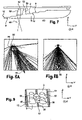
- the device 2 comprises a light guide 4 and light sources 6.
- Each source 6 has its main axis parallel to the direction Z and perpendicular to the general plane of the guide. It extends opposite a face 8 of the latter so that the light emitted by the source enters it via this face.
- Each source is for example made up of one or more LEDs.
- Device 2 comprises a flat printed circuit 16 parallel to the X and Y directions and which carries the sources so that they are located in the same plane.
- the sources 6 are arranged on the periphery of the guide opposite the face 8. We observe on the figure 5 that the sources form a curved line. In this figure, the position of the sources has been shifted relative to the guide to make them visible. This arrangement of the sources makes it possible to produce lines as explained later.
- the light guide here forms a single solid piece extending in its length along Y and in its height along Z. It is made by molding preferably a transparent plastic material, for example PMMA with a refractive index of 1 .49 or polycarbonate with a refractive index of 1.59.
- It can also be made of PC, a material which would favor the placement of the guide as an external part without the need for an additional protective screen. It comprises two main faces of generally flat shape, parallel to each other and to the X, Y plane and which extend on opposite sides of the guide. They respectively form the upper face 8 of light entry, directed towards the bodywork, and the lower face 14 of the light outlet facing the passenger compartment of the vehicle.
- the guide further comprises a face 10 which has sections of parabolic shape. These sections are parallel to the X direction. However, they are not all parallel to each other. They are oriented so that each section of the guide parallel to the direction X and passing through one of the sources 6 is parabolic.
- the source is located at the focus of the corresponding parabola.
- Face 10 reflects inside the guide at least part of the light coming from each source via main face 8 . The rays thus reflected are located in planes parallel to the X and Y directions.
- This face has a series of reliefs 30 such as gadroons illustrated in figure 14 .
- the gadroons 30 are curved towards the outside of the guide and disperse the rays in each X, Y plane.
- the guide comprises decoupling faces 12 spaced apart from each other and which each reflect independently of each other part of the light coming directly from the face 10, directly towards the exit face 14.
- the decoupling faces are at the eight species. This figure is not limiting so that it can be lower or higher than this value.
- the decoupling faces 12 are not flat. They have a rectilinear profile in each of the aforementioned sections. This rectilinear section is inclined relative to the plane of face 8 or 9 at an angle ⁇ of between 1 and 89°, advantageously of between 25 and 75° and preferably of between 35 and 65°. It is here equal to 45°.
- the decoupling faces are organized in tiers, that is to say according to an alternation of decoupling faces and flat faces 9 parallel to the X and Y axes.
- the decoupling faces 12 have reliefs 26 such as gadroons. They may also have any other relief making it possible to disperse the light outside the guide.
- the output face 14 in this case has a planar shape, it is possible to add elements allowing the dispersion of light or to give it a curved shape. It is the same for the main face8.
- the figure 14 illustrates two passages 32 passing through the wall of the guide and the faces 10 and 8 and allowing the mounting of the sources in the device when the guide is already in place facing the printed circuit. They are cut out of the material in various shapes along the X and Y axes, such as, for example, wells. However, they have no impact on the implementation of the device.
- the path of the light emitted by each source inside the guide is represented at the picture 2 and materialized by the rays 28.
- the rays 28 emitted by the source 6 propagate in the guide through the main face 8, towards the coupling face 10 which reflects them inside the guide according to planes X, Y parallel to the face 8. These rays propagate in the guide 4 until they are reflected by the decoupling faces 12 towards the exit face 14 so that they are widely visible from the outside.
- the guide can in this case form a luminous pattern illustrated in figure 4 comprising lines of light 36 extending over the exit face 14 in correlation with the positioning of the decoupling faces 12.
- the lines of light may be straight or curved and may or may not meet.
- the pattern consists of seven lines of light at varying distances from each other also having straight segments and a curved portion in the middle part.
- the photometry is homogeneous inside the lines.
- the light pattern formed by the guide is not limited to the single pattern shown in figure 4 .
- the guide can produce other patterns.
- the device comprises a cover 48 making it possible to make the printed circuit 16 invisible.
- This cover has an essentially aesthetic role by making it possible to conceal the unsightly parts of the circuit as well as any other electrical components present.
- the device further comprises directional lighting sources 52 and, for each of them, a respective light redirection member 50 capable of directing the light emitted by this source towards a focal point 60 of the member located at the outside the guide and represented schematically in figure 11 .
- the device comprises in this case two sources of this type. This number is not limiting and may be lower or higher. It is preferably between 1 and 4. These sources are three in number on the figures 11 and 12 and four on the figure 9 and 10 which illustrate variant embodiments.
- the sources 52 are carried by the printed circuit 16 and oriented with their main axis parallel to the direction Z. These sources are positioned, for the most part or in their entirety, facing planar faces 9 of the guide, between two decoupling faces 12. They can be arranged freely. For example, they can be aligned, arranged in a square, in a circle or even in a triangle as shown in figure 11 .
- Each redirection member 50 has the general shape of an ellipsoid which may present an inclination of its main axis with respect to the Z and Y directions, as shown in figure 7 .
- the redirection member is independent of the guide and fixed to the printed circuit.
- This organ reflects part of the rays coming from the source towards the focus 60 of the organ which is located outside the guide.
- the main direction of the rays is materialized by the arrow 56.
- the device has several members 50, they can be fixed to each other by a means 58 which allows them to be held together on the printed circuit or else are formed in one piece with this way.
- the sources 50 make it possible to obtain one or more light spots 62.
- the sources and members can be organized so as to generate a single light spot or so as to produce as many light spots as there are directional lighting sources and redirection members present.
- the device 20 differs from that of the figure 1 in that the main face of the light 22 and the light exit face 22 extend on the same side of the guide and preferably form one and the same face.
- the decoupling faces extend opposite the output face on the opposite side of the guide.
- the printed circuit 16 is arranged at one end of the guide opposite the face 22 and up to a limit zone corresponding to the emission zone of the light pattern.
- the other aspects of the device are unchanged.
- the rays 28 emitted by the source 6 propagate in the guide through the main face 22, towards the coupling face 10 which reflects them inside the guide according to planes substantially parallel to the face 22. These rays are reflected by the decoupling faces 12 towards the output face of the guide 22.
- the device may also include a cover 48 for aesthetic purposes in order to conceal the components of the printed circuit.
Landscapes
- Engineering & Computer Science (AREA)
- General Engineering & Computer Science (AREA)
- Mechanical Engineering (AREA)
- Physics & Mathematics (AREA)
- Microelectronics & Electronic Packaging (AREA)
- Optics & Photonics (AREA)
- Planar Illumination Modules (AREA)
- Fastening Of Light Sources Or Lamp Holders (AREA)
- Arrangements Of Lighting Devices For Vehicle Interiors, Mounting And Supporting Thereof, Circuits Therefore (AREA)
- Non-Portable Lighting Devices Or Systems Thereof (AREA)
Claims (18)
- Beleuchtungsvorrichtung einer Fahrgastzelle eines Kraftfahrzeugs, wobei die Beleuchtungsvorrichtung mindestens eine Lichtquelle (6) und einen Lichtleiter (4; 24) beinhaltet, wobei sich die Quelle (6) gegenüber einer Hauptfläche des Leiters (8; 22) erstreckt, wobei der Leiter mindestens eine Einkopplungsfläche (10), die dazu fähig ist, mindestens einen Teil des von der Quelle emittierten Lichts in den Leiter zu reflektieren, und mindestens zwei Auskopplungsflächen (12) beinhaltet, die voneinander beabstandet sind und so angeordnet sind, dass sie das Licht, das von der Einkopplungsfläche kommt, zu einer Austrittsfläche (14; 22) des Leiters reflektieren, wobei die Beleuchtungsvorrichtung ferner mindestens eine gerichtete Beleuchtungsquelle (52) und mindestens ein Umleitungsorgan (50) beinhaltet, wobei das Umleitungsorgan (50) zwischen der gerichteten Beleuchtungsquelle (52) und den Auskopplungsflächen (12) des Leiters (4; 24) eingefügt ist und so angeordnet ist, dass es das von der gerichteten Beleuchtungsquelle emittierte Licht in das Innere des Leiters überträgt, welchen es zu der Austrittsfläche (14; 22) hin durchquert, dadurch gekennzeichnet, dass das Umleitungsorgan (50) das von der gerichteten Beleuchtungsquelle emittierte Licht zu einem Brennpunkt (60) des Organs lenkt, der sich außerhalb des Leiters befindet.
- Vorrichtung nach dem vorhergehenden Anspruch, wobei die Lichtquelle eine Emissionsachse aufweist, die zu der Hauptfläche senkrecht ist.
- Vorrichtung nach einem der vorhergehenden Ansprüche, wobei die Einkopplungsfläche an einem der Enden des Leiters angeordnet ist.
- Vorrichtung nach einem der Ansprüche 1 bis 3, wobei die Einkopplungsfläche (10) einen im Wesentlichen parabolischen Querschnitt aufweist.
- Vorrichtung nach einem der Ansprüche 1 bis 4, wobei die Einkopplungsfläche mindestens ein Relief (30) beinhaltet, das dazu fähig ist, das von der Quelle emittierte Licht zu streuen.
- Vorrichtung nach einem der Ansprüche 1 bis 5, wobei mindestens eine der Auskopplungsflächen (12) mindestens ein Mittel (26) zum Streuen des Lichts beinhaltet.
- Vorrichtung nach einem der Ansprüche 1 bis 6, wobei die mindestens zwei Auskopplungsflächen durch einen Bereich interner Totalreflexion voneinander getrennt sind, sodass die Lichtstrahlen, die diesen erreichen, total reflektiert werden, sodass sie in dem Leiter eingekoppelt bleiben.
- Vorrichtung nach einem der Ansprüche 1 bis 7, die Stufen umfasst, die gegenüber der Austrittsfläche (14) angeordnet sind, wobei diese Stufen die Auskopplungsflächen (12) umfassen.
- Vorrichtung nach einem der Ansprüche 1 bis 8, wobei die Stufen aus einem Wechsel zwischen Auskopplungsflächen und Bereichen interner Totalreflexion gebildet sind.
- Vorrichtung nach einem der Ansprüche 1 bis 9, wobei jede Auskopplungsfläche (12) so angeordnet ist, dass sie die Lichtstrahlen, die sie erreichen, so reflektiert, dass durch die Austrittsfläche hindurch Streifen sichtbar sind.
- Vorrichtung nach einem der Ansprüche 1 bis 10, die eine Leiterplatte (16) beinhaltet, die zu der Hauptfläche des Leiters parallel ist.
- Vorrichtung nach einem der Ansprüche 1 bis 11, wobei der Leiter einen Durchgang (32) für die Montage der Quelle (6) durch den Leiter hindurch beinhaltet.
- Vorrichtung nach einem der Ansprüche 1 bis 12, wobei der Leiter mindestens eine vereinzelte Oberflächenunregelmäßigkeit beinhaltet, wie etwa eine Veränderung der Oberfläche, beispielsweise auf der Hauptfläche, auf der Einkopplungsfläche, auf einer der Auskopplungsflächen oder auf der Austrittsfläche.
- Vorrichtung nach einem der Ansprüche 1 bis 13, wobei sich die Austrittsfläche (14) und die Hauptfläche (8) auf gegenüberliegenden Seiten des Leiters erstrecken.
- Vorrichtung nach einem der Ansprüche 1 bis 14, wobei sich die Austrittsfläche (22) und die Hauptfläche (22) auf einer gleichen Seite des Leiters erstrecken.
- Vorrichtung nach einem der Ansprüche 1 bis 15, wobei das Umleitungsorgan (50) so angeordnet ist, dass es mindestens einen Teil des Lichts der gerichteten Beleuchtungsquelle (52) zu einem Bereich lenkt, der sich zwischen zwei Auskopplungsflächen befindet.
- Vorrichtung nach einem der Ansprüche 1 bis 16, wobei der Leiter eine variable Dicke aufweist, die in Querrichtung von einem Ende zum anderen abnimmt.
- Vorrichtung nach dem vorhergehenden Anspruch, wobei der Leiter an dem Ende, an dem die Dicke am geringsten ist, frei von Halterungen ist.
Applications Claiming Priority (2)
| Application Number | Priority Date | Filing Date | Title |
|---|---|---|---|
| FR1259013A FR2995976B1 (fr) | 2012-09-26 | 2012-09-26 | Dispositif d'eclairage et/ou de signalisation de vehicule automobile |
| PCT/EP2013/069589 WO2014048848A1 (fr) | 2012-09-26 | 2013-09-20 | Dispositif d'éclairage et/ou de signalisation de véhicule automobile |
Publications (2)
| Publication Number | Publication Date |
|---|---|
| EP2901074A1 EP2901074A1 (de) | 2015-08-05 |
| EP2901074B1 true EP2901074B1 (de) | 2022-05-18 |
Family
ID=48050819
Family Applications (1)
| Application Number | Title | Priority Date | Filing Date |
|---|---|---|---|
| EP13766035.3A Active EP2901074B1 (de) | 2012-09-26 | 2013-09-20 | Fahrzeug-signalleuchte oder -innenraumleuchte |
Country Status (5)
| Country | Link |
|---|---|
| US (1) | US9494291B2 (de) |
| EP (1) | EP2901074B1 (de) |
| JP (1) | JP6224110B2 (de) |
| FR (1) | FR2995976B1 (de) |
| WO (1) | WO2014048848A1 (de) |
Families Citing this family (29)
| Publication number | Priority date | Publication date | Assignee | Title |
|---|---|---|---|---|
| JPH0677624B2 (ja) | 1990-05-18 | 1994-10-05 | 株式会社エース電研 | 遊技機島および遊技場 |
| JP2879371B2 (ja) | 1990-11-19 | 1999-04-05 | 狭山精密工業株式会社 | パチンコ遊技店の玉補給還元システム |
| JPH0767501B2 (ja) | 1993-10-01 | 1995-07-26 | 株式会社エース電研 | 遊技場の電子管理装置 |
| GB2484713A (en) | 2010-10-21 | 2012-04-25 | Optovate Ltd | Illumination apparatus |
| FR3032517B1 (fr) * | 2015-02-05 | 2018-06-29 | Valeo Vision | Dispositif lumineux de vehicule |
| CN208107968U (zh) * | 2015-08-07 | 2018-11-16 | 3M创新有限公司 | 光导组件 |
| FR3048068B1 (fr) * | 2016-02-24 | 2022-08-05 | Valeo Vision | Systeme d'eclairage pour habitacle de vehicules automobiles |
| JP6985806B2 (ja) * | 2016-03-29 | 2021-12-22 | スタンレー電気株式会社 | 車両用灯具 |
| DE202016105104U1 (de) * | 2016-09-14 | 2017-12-15 | Zumtobel Lighting Gmbh | Anordnung zur Lichtabgabe |
| JP6948156B2 (ja) * | 2017-05-23 | 2021-10-13 | スタンレー電気株式会社 | 車両用灯具 |
| CZ308748B6 (cs) * | 2017-09-05 | 2021-04-28 | ŠKODA AUTO a.s. | Světelné zařízení motorového vozidla |
| GB201718307D0 (en) | 2017-11-05 | 2017-12-20 | Optovate Ltd | Display apparatus |
| JP7017394B2 (ja) * | 2017-12-14 | 2022-02-08 | 株式会社小糸製作所 | ライトガイド装置 |
| GB201800574D0 (en) | 2018-01-14 | 2018-02-28 | Optovate Ltd | Illumination apparatus |
| GB201803767D0 (en) * | 2018-03-09 | 2018-04-25 | Optovate Ltd | Illumination apparatus |
| GB201807747D0 (en) | 2018-05-13 | 2018-06-27 | Optovate Ltd | Colour micro-LED display apparatus |
| DE102018008228B4 (de) * | 2018-10-17 | 2022-01-27 | Daimler Ag | Beleuchtungsvorrichtung für einen Innenraum eines Fahrzeugs |
| IT201800010732A1 (it) * | 2018-11-30 | 2020-05-30 | Olsa Spa | Sistema a guida luce modulare e autoveicolo comprendente tale sistema. |
| DE102019204769A1 (de) * | 2019-04-03 | 2020-10-08 | HELLA GmbH & Co. KGaA | Beleuchtungsband |
| TWI912252B (zh) | 2019-07-02 | 2026-01-21 | 美商瑞爾D斯帕克有限責任公司 | 定向顯示設備 |
| KR102937412B1 (ko) | 2019-10-03 | 2026-03-12 | 리얼디 스파크, 엘엘씨 | 수동형 광학 나노구조를 포함하는 조명 장치 |
| US10962194B1 (en) | 2019-12-14 | 2021-03-30 | Valeo North America, Inc. | Motor vehicle light guide and reflective coupler system for outboard homogenous lit appearance of lamp module |
| US11572994B2 (en) | 2019-12-14 | 2023-02-07 | Valeo North America, Inc. | Homogeneous light emission and light guide arrangement of an automobile vehicle for a uniform lit appearance |
| CN115136065A (zh) | 2020-02-20 | 2022-09-30 | 瑞尔D斯帕克有限责任公司 | 照明和显示设备 |
| JP7435283B2 (ja) * | 2020-06-12 | 2024-02-21 | トヨタ紡織株式会社 | 照明装置 |
| FR3112317B1 (fr) * | 2020-07-07 | 2023-09-29 | Faurecia Interieur Ind | Elément de décoration lumineux et procédé de fabrication associé |
| EP4359862B1 (de) | 2021-06-22 | 2026-05-06 | RealD Spark, LLC | Beleuchtungsvorrichtung |
| US12398854B2 (en) | 2022-04-04 | 2025-08-26 | Lg Innotek Co., Ltd. | Lighting device |
| DE102023108470A1 (de) * | 2023-04-03 | 2024-10-10 | HELLA GmbH & Co. KGaA | Beleuchtungsvorrichtung für Fahrzeuge |
Citations (4)
| Publication number | Priority date | Publication date | Assignee | Title |
|---|---|---|---|---|
| US5197792A (en) * | 1992-04-21 | 1993-03-30 | General Motors Corporation | Illuminator device for a display panel |
| DE102008061716A1 (de) * | 2008-12-12 | 2010-06-17 | Bayerische Motoren Werke Aktiengesellschaft | Fahrzeugleuchte und Leuchtensystem |
| EP2338732A1 (de) * | 2009-12-16 | 2011-06-29 | Automotive Lighting Reutlingen GmbH | Kraftfahrzeugbeleuchtungseinrichtung mit einem Lichtleiter und verschiedenfarbigen Lichtquellen |
| JP2012038424A (ja) * | 2010-08-03 | 2012-02-23 | Koito Mfg Co Ltd | 車両用灯具 |
Family Cites Families (17)
| Publication number | Priority date | Publication date | Assignee | Title |
|---|---|---|---|---|
| JPH01108501U (de) * | 1988-01-16 | 1989-07-21 | ||
| JPH0455002U (de) * | 1990-09-18 | 1992-05-12 | ||
| US5365412A (en) * | 1993-01-07 | 1994-11-15 | Ford Motor Company | Low profile illuminator |
| JPH0740283U (ja) * | 1993-12-28 | 1995-07-18 | 株式会社小糸製作所 | 車輌用室内灯 |
| US5890796A (en) | 1997-01-16 | 1999-04-06 | Ford Global Technologies, Inc. | Laser illuminated lighting system utilizing a diffractive optical element |
| JP2004047220A (ja) * | 2002-07-10 | 2004-02-12 | Koito Mfg Co Ltd | 車両用灯具 |
| DE10240270A1 (de) * | 2002-08-31 | 2004-03-18 | Johnson Controls Gmbh | Verkleidungselement für den Innenraum eines Fahrzeugs |
| JP2004103379A (ja) * | 2002-09-09 | 2004-04-02 | Koito Mfg Co Ltd | 車両用標識灯 |
| JP4118647B2 (ja) * | 2002-10-24 | 2008-07-16 | 株式会社小糸製作所 | 車両用標識灯 |
| FR2853392B1 (fr) * | 2003-04-04 | 2006-06-16 | Sli Miniature Lighting Sa | Feu arriere, en particulier feu stop pour vehicule automobile |
| DE10338788A1 (de) * | 2003-08-23 | 2005-04-21 | Bayerische Motoren Werke Ag | Signalleuchte für Fahrzeuge |
| EP1917154A1 (de) * | 2005-08-16 | 2008-05-07 | Johnson Controls Technology Company | Beleuchtetes verkleidungselement für ein armaturenbrett |
| FR2898660B1 (fr) * | 2006-03-16 | 2008-06-13 | Automotive Lighting Rear Lamps | Feu de signalisation de vehicule automobile a aspect exterieur uniforme. |
| US7963689B2 (en) * | 2007-10-24 | 2011-06-21 | Kun Dian Photoelectric Enterprise Co. | LED-edgelit light guide fixture having LED receiving grooves |
| EP2384934A1 (de) * | 2010-05-07 | 2011-11-09 | odelo GmbH | Leuchtmittel zur Erfüllung mehrerer Lichtfunktionen einer Kraftfahrzeugleuchte |
| JP5506610B2 (ja) * | 2010-09-06 | 2014-05-28 | スタンレー電気株式会社 | 灯具ユニット |
| US20130135358A1 (en) * | 2011-11-30 | 2013-05-30 | Qualcomm Mems Technologies, Inc. | Light collimating manifold for producing multiple virtual light sources |
-
2012
- 2012-09-26 FR FR1259013A patent/FR2995976B1/fr active Active
-
2013
- 2013-09-20 JP JP2015533544A patent/JP6224110B2/ja active Active
- 2013-09-20 EP EP13766035.3A patent/EP2901074B1/de active Active
- 2013-09-20 US US14/430,008 patent/US9494291B2/en active Active
- 2013-09-20 WO PCT/EP2013/069589 patent/WO2014048848A1/fr not_active Ceased
Patent Citations (4)
| Publication number | Priority date | Publication date | Assignee | Title |
|---|---|---|---|---|
| US5197792A (en) * | 1992-04-21 | 1993-03-30 | General Motors Corporation | Illuminator device for a display panel |
| DE102008061716A1 (de) * | 2008-12-12 | 2010-06-17 | Bayerische Motoren Werke Aktiengesellschaft | Fahrzeugleuchte und Leuchtensystem |
| EP2338732A1 (de) * | 2009-12-16 | 2011-06-29 | Automotive Lighting Reutlingen GmbH | Kraftfahrzeugbeleuchtungseinrichtung mit einem Lichtleiter und verschiedenfarbigen Lichtquellen |
| JP2012038424A (ja) * | 2010-08-03 | 2012-02-23 | Koito Mfg Co Ltd | 車両用灯具 |
Also Published As
| Publication number | Publication date |
|---|---|
| US20150233539A1 (en) | 2015-08-20 |
| FR2995976A1 (fr) | 2014-03-28 |
| EP2901074A1 (de) | 2015-08-05 |
| US9494291B2 (en) | 2016-11-15 |
| WO2014048848A1 (fr) | 2014-04-03 |
| JP6224110B2 (ja) | 2017-11-01 |
| JP2015533713A (ja) | 2015-11-26 |
| FR2995976B1 (fr) | 2018-11-09 |
Similar Documents
| Publication | Publication Date | Title |
|---|---|---|
| FR2995976A1 (fr) | Dispositif d'eclairage et/ou de signalisation de vehicule automobile | |
| EP3124855B1 (de) | Beleuchtungsvorrichtung für kraftfahrzeugscheinwerfer | |
| FR2995977B1 (fr) | Guide de lumiere pour un dispositif d'eclairage et/ou de signalisation de vehicule automobile | |
| EP1666787B1 (de) | Beleuchtungseinrichtung für Kraftfahrzeugscheinwerfer | |
| EP2690349B1 (de) | Lichtwellenleiter für eine Beleuchtungs- und/oder Signalisierungsvorrichtung eines Kraftfahrzeugs | |
| FR3050011A1 (fr) | Module d'emission d'un faisceau lumineux pour projecteur de vehicule automobile | |
| EP3273149B1 (de) | Leuchtmodul für kraftfahrzeuge | |
| FR2858682A1 (fr) | Unite d'eclairage comportant une source lumineuse et un conducteur de lumiere | |
| EP2998645B1 (de) | Beleuchtungsvorrichtung eines fahrzeugs, die eine optische linse mit mehreren quellen verwendet | |
| FR2966223A1 (fr) | Dispositif d'eclairage ou de signalisation | |
| EP3254019A1 (de) | Zum fahren auf der linken seite und zum fahren auf der rechten seite kompatibles fahrzeugleuchtenmodul | |
| FR2984456A1 (fr) | Systeme d'eclairage pour projecteur notamment de vehicule automobile | |
| EP2999919B1 (de) | Optischer wellenleiter mit einem reflektierenden muster zur verbreitung eines lichtstrahls | |
| EP3024699A1 (de) | Beleuchtungssystem, insbesondere für ein kraftfahrzeugbeleuchtungselement, mit einem von der lichtquelle versetzten lichtemittierenden element | |
| EP1726479A2 (de) | Beleuchtungs- oder Signaleinrichtung für Kraftfahrzeuge | |
| EP4726255A2 (de) | Leuchtmodul, das die beleuchtete oberfläche eines kollektors mit störstrahlenblockern erzeugt | |
| EP2711610A1 (de) | Vorrichtung zur Beleuchtung und/oder Signalisierung, insbesondere für Kraftfahrzeuge | |
| WO2015011378A1 (fr) | Système d'éclairage, notamment pour un organe d'éclairage de véhicule automobile, a carte a circuit imprime inclinée par rapport a la direction d'éclairage | |
| FR2998644A1 (fr) | Dispositif de signalisation pour vehicule avec effet tridimensionnel | |
| FR2542063A1 (fr) | Dispositif d'eclairage anti-eblouissant | |
| WO2023088826A1 (fr) | Module lumineux avec fonctions d'éclairage et de signalisation | |
| FR3010483A1 (fr) | Dispositif d'eclairage d'habitacle de vehicule | |
| FR3008770A1 (fr) | Systeme d'eclairage modulaire, notamment pour un organe d'eclairage de vehicule automobile | |
| FR3079596A1 (fr) | Dispositif optique avec guide optique et reflecteur indexes | |
| FR2918441A1 (fr) | Projecteur de vehicule |
Legal Events
| Date | Code | Title | Description |
|---|---|---|---|
| PUAI | Public reference made under article 153(3) epc to a published international application that has entered the european phase |
Free format text: ORIGINAL CODE: 0009012 |
|
| 17P | Request for examination filed |
Effective date: 20150310 |
|
| AK | Designated contracting states |
Kind code of ref document: A1 Designated state(s): AL AT BE BG CH CY CZ DE DK EE ES FI FR GB GR HR HU IE IS IT LI LT LU LV MC MK MT NL NO PL PT RO RS SE SI SK SM TR |
|
| AX | Request for extension of the european patent |
Extension state: BA ME |
|
| DAX | Request for extension of the european patent (deleted) | ||
| STAA | Information on the status of an ep patent application or granted ep patent |
Free format text: STATUS: EXAMINATION IS IN PROGRESS |
|
| 17Q | First examination report despatched |
Effective date: 20180801 |
|
| REG | Reference to a national code |
Ref country code: DE Ref legal event code: R079 Ref document number: 602013081700 Country of ref document: DE Free format text: PREVIOUS MAIN CLASS: F21S0008100000 Ipc: B60Q0003760000 |
|
| GRAP | Despatch of communication of intention to grant a patent |
Free format text: ORIGINAL CODE: EPIDOSNIGR1 |
|
| STAA | Information on the status of an ep patent application or granted ep patent |
Free format text: STATUS: GRANT OF PATENT IS INTENDED |
|
| RIC1 | Information provided on ipc code assigned before grant |
Ipc: B60Q 3/76 20170101AFI20211110BHEP |
|
| INTG | Intention to grant announced |
Effective date: 20211214 |
|
| GRAS | Grant fee paid |
Free format text: ORIGINAL CODE: EPIDOSNIGR3 |
|
| GRAA | (expected) grant |
Free format text: ORIGINAL CODE: 0009210 |
|
| STAA | Information on the status of an ep patent application or granted ep patent |
Free format text: STATUS: THE PATENT HAS BEEN GRANTED |
|
| AK | Designated contracting states |
Kind code of ref document: B1 Designated state(s): AL AT BE BG CH CY CZ DE DK EE ES FI FR GB GR HR HU IE IS IT LI LT LU LV MC MK MT NL NO PL PT RO RS SE SI SK SM TR |
|
| REG | Reference to a national code |
Ref country code: GB Ref legal event code: FG4D Free format text: NOT ENGLISH |
|
| REG | Reference to a national code |
Ref country code: CH Ref legal event code: EP |
|
| REG | Reference to a national code |
Ref country code: IE Ref legal event code: FG4D Free format text: LANGUAGE OF EP DOCUMENT: FRENCH |
|
| REG | Reference to a national code |
Ref country code: DE Ref legal event code: R096 Ref document number: 602013081700 Country of ref document: DE |
|
| REG | Reference to a national code |
Ref country code: AT Ref legal event code: REF Ref document number: 1492986 Country of ref document: AT Kind code of ref document: T Effective date: 20220615 |
|
| REG | Reference to a national code |
Ref country code: LT Ref legal event code: MG9D |
|
| REG | Reference to a national code |
Ref country code: NL Ref legal event code: MP Effective date: 20220518 |
|
| REG | Reference to a national code |
Ref country code: AT Ref legal event code: MK05 Ref document number: 1492986 Country of ref document: AT Kind code of ref document: T Effective date: 20220518 |
|
| PG25 | Lapsed in a contracting state [announced via postgrant information from national office to epo] |
Ref country code: SE Free format text: LAPSE BECAUSE OF FAILURE TO SUBMIT A TRANSLATION OF THE DESCRIPTION OR TO PAY THE FEE WITHIN THE PRESCRIBED TIME-LIMIT Effective date: 20220518 Ref country code: PT Free format text: LAPSE BECAUSE OF FAILURE TO SUBMIT A TRANSLATION OF THE DESCRIPTION OR TO PAY THE FEE WITHIN THE PRESCRIBED TIME-LIMIT Effective date: 20220919 Ref country code: NO Free format text: LAPSE BECAUSE OF FAILURE TO SUBMIT A TRANSLATION OF THE DESCRIPTION OR TO PAY THE FEE WITHIN THE PRESCRIBED TIME-LIMIT Effective date: 20220818 Ref country code: NL Free format text: LAPSE BECAUSE OF FAILURE TO SUBMIT A TRANSLATION OF THE DESCRIPTION OR TO PAY THE FEE WITHIN THE PRESCRIBED TIME-LIMIT Effective date: 20220518 Ref country code: LT Free format text: LAPSE BECAUSE OF FAILURE TO SUBMIT A TRANSLATION OF THE DESCRIPTION OR TO PAY THE FEE WITHIN THE PRESCRIBED TIME-LIMIT Effective date: 20220518 Ref country code: HR Free format text: LAPSE BECAUSE OF FAILURE TO SUBMIT A TRANSLATION OF THE DESCRIPTION OR TO PAY THE FEE WITHIN THE PRESCRIBED TIME-LIMIT Effective date: 20220518 Ref country code: GR Free format text: LAPSE BECAUSE OF FAILURE TO SUBMIT A TRANSLATION OF THE DESCRIPTION OR TO PAY THE FEE WITHIN THE PRESCRIBED TIME-LIMIT Effective date: 20220819 Ref country code: FI Free format text: LAPSE BECAUSE OF FAILURE TO SUBMIT A TRANSLATION OF THE DESCRIPTION OR TO PAY THE FEE WITHIN THE PRESCRIBED TIME-LIMIT Effective date: 20220518 Ref country code: ES Free format text: LAPSE BECAUSE OF FAILURE TO SUBMIT A TRANSLATION OF THE DESCRIPTION OR TO PAY THE FEE WITHIN THE PRESCRIBED TIME-LIMIT Effective date: 20220518 Ref country code: BG Free format text: LAPSE BECAUSE OF FAILURE TO SUBMIT A TRANSLATION OF THE DESCRIPTION OR TO PAY THE FEE WITHIN THE PRESCRIBED TIME-LIMIT Effective date: 20220818 Ref country code: AT Free format text: LAPSE BECAUSE OF FAILURE TO SUBMIT A TRANSLATION OF THE DESCRIPTION OR TO PAY THE FEE WITHIN THE PRESCRIBED TIME-LIMIT Effective date: 20220518 |
|
| PG25 | Lapsed in a contracting state [announced via postgrant information from national office to epo] |
Ref country code: RS Free format text: LAPSE BECAUSE OF FAILURE TO SUBMIT A TRANSLATION OF THE DESCRIPTION OR TO PAY THE FEE WITHIN THE PRESCRIBED TIME-LIMIT Effective date: 20220518 Ref country code: PL Free format text: LAPSE BECAUSE OF FAILURE TO SUBMIT A TRANSLATION OF THE DESCRIPTION OR TO PAY THE FEE WITHIN THE PRESCRIBED TIME-LIMIT Effective date: 20220518 Ref country code: LV Free format text: LAPSE BECAUSE OF FAILURE TO SUBMIT A TRANSLATION OF THE DESCRIPTION OR TO PAY THE FEE WITHIN THE PRESCRIBED TIME-LIMIT Effective date: 20220518 Ref country code: IS Free format text: LAPSE BECAUSE OF FAILURE TO SUBMIT A TRANSLATION OF THE DESCRIPTION OR TO PAY THE FEE WITHIN THE PRESCRIBED TIME-LIMIT Effective date: 20220918 |
|
| PG25 | Lapsed in a contracting state [announced via postgrant information from national office to epo] |
Ref country code: SM Free format text: LAPSE BECAUSE OF FAILURE TO SUBMIT A TRANSLATION OF THE DESCRIPTION OR TO PAY THE FEE WITHIN THE PRESCRIBED TIME-LIMIT Effective date: 20220518 Ref country code: SK Free format text: LAPSE BECAUSE OF FAILURE TO SUBMIT A TRANSLATION OF THE DESCRIPTION OR TO PAY THE FEE WITHIN THE PRESCRIBED TIME-LIMIT Effective date: 20220518 Ref country code: RO Free format text: LAPSE BECAUSE OF FAILURE TO SUBMIT A TRANSLATION OF THE DESCRIPTION OR TO PAY THE FEE WITHIN THE PRESCRIBED TIME-LIMIT Effective date: 20220518 Ref country code: EE Free format text: LAPSE BECAUSE OF FAILURE TO SUBMIT A TRANSLATION OF THE DESCRIPTION OR TO PAY THE FEE WITHIN THE PRESCRIBED TIME-LIMIT Effective date: 20220518 Ref country code: DK Free format text: LAPSE BECAUSE OF FAILURE TO SUBMIT A TRANSLATION OF THE DESCRIPTION OR TO PAY THE FEE WITHIN THE PRESCRIBED TIME-LIMIT Effective date: 20220518 Ref country code: CZ Free format text: LAPSE BECAUSE OF FAILURE TO SUBMIT A TRANSLATION OF THE DESCRIPTION OR TO PAY THE FEE WITHIN THE PRESCRIBED TIME-LIMIT Effective date: 20220518 |
|
| REG | Reference to a national code |
Ref country code: DE Ref legal event code: R097 Ref document number: 602013081700 Country of ref document: DE |
|
| PLBE | No opposition filed within time limit |
Free format text: ORIGINAL CODE: 0009261 |
|
| STAA | Information on the status of an ep patent application or granted ep patent |
Free format text: STATUS: NO OPPOSITION FILED WITHIN TIME LIMIT |
|
| PG25 | Lapsed in a contracting state [announced via postgrant information from national office to epo] |
Ref country code: AL Free format text: LAPSE BECAUSE OF FAILURE TO SUBMIT A TRANSLATION OF THE DESCRIPTION OR TO PAY THE FEE WITHIN THE PRESCRIBED TIME-LIMIT Effective date: 20220518 |
|
| 26N | No opposition filed |
Effective date: 20230221 |
|
| PG25 | Lapsed in a contracting state [announced via postgrant information from national office to epo] |
Ref country code: MC Free format text: LAPSE BECAUSE OF FAILURE TO SUBMIT A TRANSLATION OF THE DESCRIPTION OR TO PAY THE FEE WITHIN THE PRESCRIBED TIME-LIMIT Effective date: 20220518 |
|
| REG | Reference to a national code |
Ref country code: CH Ref legal event code: PL |
|
| GBPC | Gb: european patent ceased through non-payment of renewal fee |
Effective date: 20220920 |
|
| REG | Reference to a national code |
Ref country code: BE Ref legal event code: MM Effective date: 20220930 |
|
| PG25 | Lapsed in a contracting state [announced via postgrant information from national office to epo] |
Ref country code: SI Free format text: LAPSE BECAUSE OF FAILURE TO SUBMIT A TRANSLATION OF THE DESCRIPTION OR TO PAY THE FEE WITHIN THE PRESCRIBED TIME-LIMIT Effective date: 20220518 |
|
| PG25 | Lapsed in a contracting state [announced via postgrant information from national office to epo] |
Ref country code: LU Free format text: LAPSE BECAUSE OF NON-PAYMENT OF DUE FEES Effective date: 20220920 |
|
| P01 | Opt-out of the competence of the unified patent court (upc) registered |
Effective date: 20230528 |
|
| PG25 | Lapsed in a contracting state [announced via postgrant information from national office to epo] |
Ref country code: LI Free format text: LAPSE BECAUSE OF NON-PAYMENT OF DUE FEES Effective date: 20220930 Ref country code: IE Free format text: LAPSE BECAUSE OF NON-PAYMENT OF DUE FEES Effective date: 20220920 Ref country code: CH Free format text: LAPSE BECAUSE OF NON-PAYMENT OF DUE FEES Effective date: 20220930 |
|
| PG25 | Lapsed in a contracting state [announced via postgrant information from national office to epo] |
Ref country code: BE Free format text: LAPSE BECAUSE OF NON-PAYMENT OF DUE FEES Effective date: 20220930 |
|
| PG25 | Lapsed in a contracting state [announced via postgrant information from national office to epo] |
Ref country code: GB Free format text: LAPSE BECAUSE OF NON-PAYMENT OF DUE FEES Effective date: 20220920 |
|
| PG25 | Lapsed in a contracting state [announced via postgrant information from national office to epo] |
Ref country code: IT Free format text: LAPSE BECAUSE OF FAILURE TO SUBMIT A TRANSLATION OF THE DESCRIPTION OR TO PAY THE FEE WITHIN THE PRESCRIBED TIME-LIMIT Effective date: 20220518 |
|
| PG25 | Lapsed in a contracting state [announced via postgrant information from national office to epo] |
Ref country code: HU Free format text: LAPSE BECAUSE OF FAILURE TO SUBMIT A TRANSLATION OF THE DESCRIPTION OR TO PAY THE FEE WITHIN THE PRESCRIBED TIME-LIMIT; INVALID AB INITIO Effective date: 20130920 |
|
| PG25 | Lapsed in a contracting state [announced via postgrant information from national office to epo] |
Ref country code: CY Free format text: LAPSE BECAUSE OF FAILURE TO SUBMIT A TRANSLATION OF THE DESCRIPTION OR TO PAY THE FEE WITHIN THE PRESCRIBED TIME-LIMIT Effective date: 20220511 |
|
| PG25 | Lapsed in a contracting state [announced via postgrant information from national office to epo] |
Ref country code: MK Free format text: LAPSE BECAUSE OF FAILURE TO SUBMIT A TRANSLATION OF THE DESCRIPTION OR TO PAY THE FEE WITHIN THE PRESCRIBED TIME-LIMIT Effective date: 20220511 |
|
| PG25 | Lapsed in a contracting state [announced via postgrant information from national office to epo] |
Ref country code: MT Free format text: LAPSE BECAUSE OF FAILURE TO SUBMIT A TRANSLATION OF THE DESCRIPTION OR TO PAY THE FEE WITHIN THE PRESCRIBED TIME-LIMIT Effective date: 20220511 |
|
| PG25 | Lapsed in a contracting state [announced via postgrant information from national office to epo] |
Ref country code: BG Free format text: LAPSE BECAUSE OF FAILURE TO SUBMIT A TRANSLATION OF THE DESCRIPTION OR TO PAY THE FEE WITHIN THE PRESCRIBED TIME-LIMIT Effective date: 20220518 |
|
| PG25 | Lapsed in a contracting state [announced via postgrant information from national office to epo] |
Ref country code: BG Free format text: LAPSE BECAUSE OF FAILURE TO SUBMIT A TRANSLATION OF THE DESCRIPTION OR TO PAY THE FEE WITHIN THE PRESCRIBED TIME-LIMIT Effective date: 20220518 |
|
| PGFP | Annual fee paid to national office [announced via postgrant information from national office to epo] |
Ref country code: DE Payment date: 20250916 Year of fee payment: 13 |
|
| PGFP | Annual fee paid to national office [announced via postgrant information from national office to epo] |
Ref country code: FR Payment date: 20250929 Year of fee payment: 13 |
|
| PG25 | Lapsed in a contracting state [announced via postgrant information from national office to epo] |
Ref country code: TR Free format text: LAPSE BECAUSE OF FAILURE TO SUBMIT A TRANSLATION OF THE DESCRIPTION OR TO PAY THE FEE WITHIN THE PRESCRIBED TIME-LIMIT Effective date: 20220518 |