EP2901200B1 - Methode zur optimierung der anordnung piezoelektrischer aktuatoren für eine deformierbare linse - Google Patents
Methode zur optimierung der anordnung piezoelektrischer aktuatoren für eine deformierbare linse Download PDFInfo
- Publication number
- EP2901200B1 EP2901200B1 EP13770857.4A EP13770857A EP2901200B1 EP 2901200 B1 EP2901200 B1 EP 2901200B1 EP 13770857 A EP13770857 A EP 13770857A EP 2901200 B1 EP2901200 B1 EP 2901200B1
- Authority
- EP
- European Patent Office
- Prior art keywords
- lens body
- electrodes
- electrode
- piezoelectric
- electrical connection
- Prior art date
- Legal status (The legal status is an assumption and is not a legal conclusion. Google has not performed a legal analysis and makes no representation as to the accuracy of the status listed.)
- Active
Links
Images


Classifications
-
- G—PHYSICS
- G02—OPTICS
- G02B—OPTICAL ELEMENTS, SYSTEMS OR APPARATUS
- G02B3/00—Simple or compound lenses
- G02B3/12—Fluid-filled or evacuated lenses
- G02B3/14—Fluid-filled or evacuated lenses of variable focal length
-
- G—PHYSICS
- G03—PHOTOGRAPHY; CINEMATOGRAPHY; ANALOGOUS TECHNIQUES USING WAVES OTHER THAN OPTICAL WAVES; ELECTROGRAPHY; HOLOGRAPHY
- G03B—APPARATUS OR ARRANGEMENTS FOR TAKING PHOTOGRAPHS OR FOR PROJECTING OR VIEWING THEM; APPARATUS OR ARRANGEMENTS EMPLOYING ANALOGOUS TECHNIQUES USING WAVES OTHER THAN OPTICAL WAVES; ACCESSORIES THEREFOR
- G03B3/00—Focusing arrangements of general interest for cameras, projectors or printers
- G03B3/10—Power-operated focusing
-
- H—ELECTRICITY
- H10—SEMICONDUCTOR DEVICES; ELECTRIC SOLID-STATE DEVICES NOT OTHERWISE PROVIDED FOR
- H10N—ELECTRIC SOLID-STATE DEVICES NOT OTHERWISE PROVIDED FOR
- H10N30/00—Piezoelectric or electrostrictive devices
- H10N30/80—Constructional details
- H10N30/87—Electrodes or interconnections, e.g. leads or terminals
-
- G—PHYSICS
- G03—PHOTOGRAPHY; CINEMATOGRAPHY; ANALOGOUS TECHNIQUES USING WAVES OTHER THAN OPTICAL WAVES; ELECTROGRAPHY; HOLOGRAPHY
- G03B—APPARATUS OR ARRANGEMENTS FOR TAKING PHOTOGRAPHS OR FOR PROJECTING OR VIEWING THEM; APPARATUS OR ARRANGEMENTS EMPLOYING ANALOGOUS TECHNIQUES USING WAVES OTHER THAN OPTICAL WAVES; ACCESSORIES THEREFOR
- G03B2205/00—Adjustment of optical system relative to image or object surface other than for focusing
- G03B2205/0053—Driving means for the movement of one or more optical element
- G03B2205/0061—Driving means for the movement of one or more optical element using piezoelectric actuators
-
- H—ELECTRICITY
- H10—SEMICONDUCTOR DEVICES; ELECTRIC SOLID-STATE DEVICES NOT OTHERWISE PROVIDED FOR
- H10N—ELECTRIC SOLID-STATE DEVICES NOT OTHERWISE PROVIDED FOR
- H10N30/00—Piezoelectric or electrostrictive devices
- H10N30/20—Piezoelectric or electrostrictive devices with electrical input and mechanical output, e.g. functioning as actuators or vibrators
- H10N30/204—Piezoelectric or electrostrictive devices with electrical input and mechanical output, e.g. functioning as actuators or vibrators using bending displacement, e.g. unimorph, bimorph or multimorph cantilever or membrane benders
- H10N30/2047—Membrane type
-
- Y—GENERAL TAGGING OF NEW TECHNOLOGICAL DEVELOPMENTS; GENERAL TAGGING OF CROSS-SECTIONAL TECHNOLOGIES SPANNING OVER SEVERAL SECTIONS OF THE IPC; TECHNICAL SUBJECTS COVERED BY FORMER USPC CROSS-REFERENCE ART COLLECTIONS [XRACs] AND DIGESTS
- Y10—TECHNICAL SUBJECTS COVERED BY FORMER USPC
- Y10T—TECHNICAL SUBJECTS COVERED BY FORMER US CLASSIFICATION
- Y10T29/00—Metal working
- Y10T29/42—Piezoelectric device making
Definitions
- the present invention relates to piezoelectric elements and especially to piezoelectric elements arranged in an Interdigitated Electrode configuration on a surface of a micro-tuneable lens body, wherein the piezoelectric elements are configurable to provide a desired shaping of the micro-tuneable lens body when activated.
- Improvements to the design of existing micro-tuneable lenses for example are critical to ensure that the devices are more readily suitable for its target application in high-volume consumer electronic devices (e.g. cameras within mobile-phones, PC's, digital scanners, etc.).
- An example of an improved micro-tuneable lens is disclosed in the patent EP 2115500 with the title "Flexible lens assembly with variable focal length" having a flexible lens body 10 in a cavity bounded by a sidewall 11 and a first transparent cover 13, and a second transparent cover 14, wherein both covers 13, 14 are in contact with respective surfaces of the lens body 10.
- Piezoelectric elements 12 are shaping the lens body 10 when activated, thereby adjusting for example the focal length of the lens assembly.
- the referenced example of an improved micro-tuneable lens utilizes piezoelectric electrodes of a conventional design, i.e. an upper and a lower metal layer with a ferroelectric layer in between the two metal layers (ref. fig. 2 ).
- This type of piezoelectric electrode has proved to be able to provide autofocus capability for camera systems, and is regarded as a replacement technology for the more common Voice Coil Motor (VCM) systems in use in mobile phone cameras.
- VCM Voice Coil Motor
- the same type of piezoelectric electrode configurations can be used in Optical Image Stabilization systems, for example as disclosed in the European Patent application EP 08712670 .
- a piezoelectric electrode with fewer layers would be beneficial.
- an electrode configuration named Interdigitated Electrodes that can be manufactured with for example respective positive and negative electrodes that are located spaced apart from each other on top of a ferroelectric layer surface on top of an insulating substrate (ref. fig. 1 ).
- Figure 6 also discloses how the electric field lines between the electrodes penetrates the ferroelectric (piezoelectric) layer, and the piezoelectric effect manifests itself when, for example, alternating voltages are applied on the electrodes, and the length of the piezo crystals are respectively lengthened or shortened, thereby producing a bending upwards or downwards of the surface, which then are mechanically transferred to the sound membrane member which then can reproduce sound.
- the electrodes are positioned on top of the ferroelectric layer, there will be no electric field directly under the surface of the electrodes facing the ferroelectric layer. Therefore, the electric field lines penetrating the ferroelectric (piezoelectric) layer are shaped with a curved shape in between the electrodes.
- United States patent US 5,451,769 disclose a high speed photo detector that in an example of embodiment as depicted in figure 3 is arranged with an Interdigitated Electrode configuration comprising two electrodes of opposite polarity, wherein each respective electrode comprises a radially oriented electrode part wherein circle shaped parts are connected and which constitutes rings around the centre of the photo detector.
- this configuration has also dead zones, but the specific application of the Interdigitated Electrode does not affect the performance of the application as part of a photo detector.
- a micro-tuneable lens with Interdigitated Electrode configured piezoelectric actuators may achieve improved optical performance and versatility if the electrodes are arranged in a configured array providing a mitigation of the dead zone phenomena of Interdigitated Electrodes.
- an improved piezoelectric actuator configuration would be advantageous, and in particular it would be more efficient to manufacture a micro-tuneable lens which has an improved piezoelectric actuator configuration, and which would provide the following examples of improvements:
- an Interdigitated Electrode configuration comprising piezoelectric actuator(s) used in a micro-tuneable lens that solves the above mentioned problems of the prior art with a configurable array of electrodes providing a definable symmetrical or non-symmetrical shaping of the lens body.
- the above described object and several other objects are intended to be obtained in a first aspect of the present invention by providing a system and a method of identifying a specific Interdigitated Electrode pattern comprising piezoelectric actuators located around an aperture of a flexible lens body, or example made out of transparent polymer, wherein the Interdigitated Electrode configuration is configurable, when activated, to provide a specific definable bending force distribution, thereby providing a specific definable shaping of the flexible lens body, thereby providing specific definable optical characteristics of the flexible lens body.
- an aperture of a flexible lens body is in the present context to be construed widely, such as an absence of electrodes on the lens body and not necessarily a physical opening as such.
- the invention is particularly, but not exclusively, advantageous for obtaining a micro-tuneable flexible lens comprising a piezoelectric electrode pattern being identified by a method of optimizing piezoelectric actuator shaping of the micro-tuneable lens body, comprising steps of:
- the invention is particularly, but not exclusively, advantageous for obtaining a computer system configurable to provide optimization of piezoelectric actuator configurations on top of a surface of a flexible lens body, comprising:
- an Interdigitated Electrode of a general design which comprises an array of positive electrodes 11 and negative electrodes 12 ordered in sequence of opposing polarities located on or in the piezoelectric layer 10.
- a piezoelectric layer utilizing an Interdigitated Electrode is configurable to provide a bending of a flexural actuator in a hetero-morph layer structure (piezoelectric film on top of passive elastic layer), which should give approximately twice as much bending force when compared to a piezoelectric layer of the more conventional parallel plate geometry, for example as disclosed in figure 2 .
- the actuation force of an Interdigitated Electrode configured piezoelectric element is constituted by the longitudinal piezoelectric coefficient (d 33 ), whereas the parallel plate geometry is based on the transverse piezoelectric coefficient (d 31 ). Since the d33 of a Lead Zirconate Titanate (a piezoelectric ceramics denoted PZT) is generally two times larger than the d31, this means that the piezoelectric strain in the longitudinal direction is expected to be two times larger than in the transverse direction with the same applied electric field. See for example the reference B. Xu, Y. Ye, L.E.Cross, J.J.
- a further advantage of Interdigitated Electrodes is the fact that the piezoelectric stress is compressive in the film plane for the Interdigitated Electrode (positive coefficient e 33 ). This is in contrast to the tensile piezoelectric stress in parallel plate geometry (negative coefficient e 31 ). Especially, if the film is already under tensile stress (like sol-gel deposited PZT thin films), the Interdigitated Electrode configuration allows for larger amplitudes of the electric field without the risk of providing film cracking.
- FIG. 3 The principle is shown in figure 3 .
- the piezoelectric stress developed in the thin films exerts a bending moment onto a neutral plane of the elastic plate or cantilever, whereby a bending occurs.
- Figure 3 is taken from Muralt, P., "Ferroelectric thin films for micro-sensors and actuators: a review", Micromech. Microeng., 2000. 10(2): p136-146 .
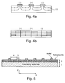
- FIG 4a it is disclosed how electric field lines 13 penetrate the piezoelectric material underneath the electrodes on the surface when a signal or voltage is applied on the electrodes with sequentially arranged opposite electric polarity.
- the figure 4a illustrate that the electric field is reduced underneath the electrodes which creates 'dead zones' in the ferroelectric material due to the absences of a suitable oriented electric field (as depicted in figure 4b).
- Figure 4b illustrates how field lines preferably should be penetrating the material.
- the Interdigitated Electrode configuration may therefore provide a non-uniform electric field which results in internal stresses and irregular strains in the piezoelectric material.
- an Interdigitated Electrode pattern consists of concentric circular or polygonal rings with a common origin
- the individual rings must be connected together to complete the electric circuit.
- the connecting electrical connections are typically out of plane of the concentric circles, and provide passive regions which do not contribute to the actuating force bending the membrane. This is in contrast to a conventional plate geometry which may provide field lines as disclosed in figure 4b .
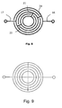
- an electrode pattern is disclosed wherein an aperture of a flexible lens body is in the centre, and the electrodes are arranged as concentric rings (branches) around the aperture.
- Two radially oriented electrodes 14, 15 with opposite polarity are interconnecting, via electrical connections between the rings (branches), respective concentric rings (branches) belonging to the specific radially oriented electrode, i.e. having the same electric polarity.
- the deflection or bending force at point A in the figure radially oriented electrode lines does not allow for any force in the preferred direction
- 'dead zones' The absences of bending force in the preferred direction associated with the radially oriented electrical connections are referred to as 'dead zones' as disclosed above. If a piezoelectric actuator with Interdigitated Electrodes are to be used in a micro-tuneable lens, the shape and curvature of the lens during the actuation is highly critical for the quality of optical functions and performance of the lens and the application of the lens.
- Interdigitated Electrode configurations are beneficial to use in micro-tuneable lens applications due to reduced cost and complexity of producing piezoelectric actuators based on Interdigitated Electrode patterns, and the increase in optical performance of lenses that may be achieved due to increasable bending forces by the same actuator configurations.
- a bending force uniformity of a certain defined quality for example smoothness of the lens surface when being shaped by the actuators
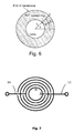
- FIG 5 which illustrates some critical parameters that may be modified to optimize the bending performance of the illustrated actuator.
- These parameters includes the width b of the electrode, separation distance a between the positive and negative electrodes, thickness of the piezoelectric (ferroelectric) material p and thickness t of an insulating substrate, for example a glass cover.
- the electrode configuration will span over a certain length of the ferroelectric substrate surface dependent on parameter values of the parameters a, b, and this may be provided for as a number of electrode repeat units ( a + b ), for example.
- the resultant displacement function, u(x), of the piezoelectric stress bending has a constant second derivative proportional to the applied electric field.
- u 1 1 2 ca 2 + ca ⁇ b
- the moment per length is abbreviated as ⁇ p .
- ⁇ p 1 2 T pr t p t e , where T pr is the piezoelectric stress along the r or x direction.
- the factor 1 ⁇ 2 comes from the approximation that the neutral plane is in the centre of the glass layer.
- the deflection is obtained from the integration of the curvature (c, equation 1).
- the first term gives the deflection without force.
- the deflection in absence of forces at the inner end of the cantilevers can be written as an integral (in contrast to the previous section):
- ⁇ p is an average value that needs to be calculated according to equation 13.
- the variation of the force is thus the same as the variation of the excursion.
- equation 19 is compatible with equation 17. It is clear that corrections by the electrode distance only would result in larger variations in electric fields. It is therefore possible to carefully alter electrode distribution scenarios in order to homogenize the force development at the end of the sections. In addition, for a complex problem of a soft lens deformation a finite element modelling is possible.
- Example 1 Irregularly segmented circle.
- the radial connections must be distributed in a geometric manner to obtain the desired effect of mitigating the effect of dead zones.
- the radial oriented electrical connections between concentric partly ring-shaped electrodes of the piezoelectric elements have to be distributed evenly such that the 'radial dead zones' are balanced and a homogeneous force distribution may be the result.
- the Interdigitated Electrode for a circle is depicted in figure 8 .
- Symmetrical positioning of the radial electrical connections may be achieved by segmenting the circle into a defined number of sectors, for example 4 quadrants as depicted figure 9 , or by dividing the circle by angular degrees.
- a non-uniform bending force distribution may be configurable if the electrodes are arranged in a non-symmetrical pattern about the central optical axis of the lens.
- Example 2 Irregularly segmented polygon.
- the radial connections are distributed according to the symmetrical properties of a polygon, most typically placed at junctures between two sides of the polygon.
- a polygon with n equal to or greater than 8 is preferred.
- Figure 10 illustrates the example of an Interdigitated Electrode pattern for a hexagon, where the radial connections are distributed symmetrically providing a uniform bending forces distribution.
- Example 3 Sliced circle with regular segmentation.
- a circular Interdigitated Electrode is segmented into an even number of equally sized 'slices' in order to evenly distribute the radial connections, cf. Figure 11 . Although a greater number of radial dead zones exist here, symmetrical force configuration about the central optical axis is possible.
- Figure 11 illustrates an example of an Interdigitated Electrode pattern for a circle divided into 8 sections, where the radial connections are distributed symmetrically.
- a piezoelectric actuator is arranged as a bimorph structure (i.e. a piezoelectric element on both sides of for example the insulating element, or a transparent elastic membrane substrate, for example a glass cover) in order to enable the actuator to operate in both directions perpendicular to a horizontal plane direction.
- a bimorph structure i.e. a piezoelectric element on both sides of for example the insulating element, or a transparent elastic membrane substrate, for example a glass cover
- This will provide a configurable control over the curvature provided for by the actuators, and depending on the positioning, size and thickness of the Interdigitated Electrode located on a top and bottom side of a membrane, a biasing of bending force direction is possible.
- the occurrence of dead zones of the ferroelectric/piezoelectric actuator with Interdigitated Electrodes on a top surface may be reduced by introducing adjacent electrodes on both sides of the actuator layer, or by embedding the electrodes within the actuator layer.
- a process simplification is achieved by the fact that the piezoelectric layer may be deposited directly onto a buffer layer which is electrically insulating. Such a buffer layer should not be chemically reactive with the piezoelectric material, and should also minimize any diffusion between the two layers. Such a configuration removes the need for a costly bottom electrode such as a platinum layer. This process simplification removes one electrode layer compared with the standard parallel capacitor piezoelectric element (see figures 1 and 2 for comparison).
- the electrodes can be located on top, or underneath, or on both sides of the piezoelectric material.
- the electrode, piezoelectric material and membrane can be arranged in all different permutations of layers.
- the step of providing an initial arrangement of the electrodes on the flexible lens body surface comprises arranging the structure of the electrode and piezoelectric material and membrane in one of the possible permutaions of layers. These permutations comprises also the possibility to arrange stacks of piezoelectric elements.
- a system and a method thereof enabling identification of an Interdigitated Electrode configuration comprises using a program with a graphical interface providing configurable graphical manipulations of an Interdigitated Electrode configuration on a surface of a flexible lens body, wherein data output describing the manipulated geometry of a specific Interdigitated Electrode configuration may be transferred to a simulator system comprising a model of the physics of a specific flexible lens body.
- the physics of the piezoelectric actuators with Interdigitated Electrodes on the surface is also modelled. In this manner it is possible to provide a starting configuration of a specific electrode configuration and then simulate the result, then go back and make a possible change in the configuration and then simulate again.
- This target measure may be a measure of optical properties of a lens body simulated in a simulator, which for example can reflect how even the bending forces are distributed on the surface of the lens, or if a certain defined nonuniform bending force distribution is achieved providing a correction of a lens flaw or error, and/or if a certain optical power has been reached.
- the physics simulation tool COMSOL described on the link http://www.comsol.com/ comprises a simulator system that can be used in an electrode configuration process as described above.
- the system comprises multi physics modeling tools than makes it simple to build a physical simulation model of a flexible lens body with arranged piezoelectric actuators configurable with Interdigitated Electrodes.
- the COMSOL system has respective interfaces for receiving output data from a plurality of different Computer Aided Design systems that can be connected automatically with a model of a physical system.
- a program module provides automatic manipulations of geometries of electrode configurations and output data in a selected Computer Aided Design tool format as input to the simulator model.
- the COMSOL system provides also tools for formatting reported results from a simulation run that can be used to provide a change of a configuration of electrodes.
- a method of arranging Interdigitated Electrodes of piezoelectric material on a surface of a flexible lens body comprises building a simulation model executable in a computer system of an initial arrangement of the Interdigitated Electrodes on the flexible lens body surface.
- the initial arrangement may be as depicted in figure 7 .
- the initial arrangement may also comprise splitting electrodes in electrical connections and distributing electrical connections of the Interdigitated Electrodes at random across the surface of the flexible lens body surface.
- the distribution may also be according to a defined symmetrical geometrical distribution, or via a defined irregular geometrical distribution. It is also within the scope of the present invention to insert extra Interdigitated Electrodes in the configuration, or removing an Interdigitated Electrode if necessary to achieve a target measure for the bending force distribution.
- the method comprises further transferring the initial defined configuration of the Interdigitated Electrodes to a simulator, and then perform iteration steps, wherein each iteration step terminates with comparing the resulting bending force distribution with (for example indirectly by simulating optical characteristics of the configuration on the lens surface), a target measure for the bending force distribution, for example how even the bending of the surface is.
- the simulation may terminate and the identified Interdigitated Electrode configuration may be applied in a manufacturing process as known to a person skilled in the art.
- an iteration step of the example of method above may comprise selecting at random an electrical connection between concentric partly ring-shaped branches of a first radially oriented electrode part and move the electrical connection in a randomly selected direction around a circle shaped path of the partly ring-shaped branches. Further, a corresponding electrical connection of a second radially oriented electrode part is moved to a diagonally opposite located location on the circle shaped path.
- an electrical connection being moved is moved in such a manner to provide a balancing of the effect of the dead zone beneath the electrical connection itself.
- the electrical connection 21 of the radially oriented electrode 16 has been moved towards the point B depicted in figure 7 which have a maximum bending force extending from the point A which has a minimum bending force due to the dead zone. How far one should move the electrical connection 21 can be selected by defining a fraction of the distance, or by the maximum bending force in point B.
- the movement may be guided by a definition of a local bending force target measure. It is also within the scope of the present invention of using mean values or other statistical measures as target measures.
- typical thicknesses of concentric partly ring-shaped electrodes of the piezoelectric elements are built up by an adhesion/seed layer of ZrO 2 , or TiO 2 in the range of 10nm to 1 ⁇ m thickness, typically 30nm.
- PZT material is typically deposited in a range of 0.5 to 4 ⁇ m, typically 2 ⁇ m.
- Electric connectors of the radially configured electrode parts are typically a metal electrode (e.g. Au/Al/Ag etc.) with a thickness in the range of 30nm to 1 ⁇ m, typically 100nm.
- a metal electrode e.g. Au/Al/Ag etc.
- the flexible lens body may be constituted by materials like glass, or other transparent materials.
Landscapes
- Physics & Mathematics (AREA)
- General Physics & Mathematics (AREA)
- Optics & Photonics (AREA)
- Lens Barrels (AREA)
- Mechanical Light Control Or Optical Switches (AREA)
- General Electrical Machinery Utilizing Piezoelectricity, Electrostriction Or Magnetostriction (AREA)
Claims (17)
- Verfahren zur Optimierung einer Anordnung piezoelektrischer Aktuatoren eines mikroabstimmbaren Linsenkörpers, wobei das Verfahren das Erstellen eines Simulationsmodells einschließt, das auf einem Computersystem mit einer Erstanordnung interdigitaler Elektroden auf einer Fläche des flexiblen Linsenkörpers ausführbar ist durch:- Anordnen konzentrischer kreisförmiger oder polygonal geformter piezoelektrischer Elemente, umfassend Elektroden, die auf einer Fläche eines piezoelektrischen Materials konfiguriert sind, das auf einer Fläche eines flexiblen Linsenkörpers abgeschieden ist, wodurch piezoelektrische Aktuatoren auf der Fläche des flexiblen Linsenkörpers um einen mittig angeordneten transparenten Teil des Linsenkörpers ausgebildet sind,- wobei die piezoelektrischen Aktuatoren eine erste positive Elektrode und eine zweite negative Elektrode umfassen, die jeweils einen radial konfigurierten Elektrodenteil umfassen, der mit Verzweigungen von konzentrischen kreisförmigen oder polygonal geformten Elektroden, die den transparenten Teil des Linsenkörpers umgeben, konfiguriert ist,- Verzweigungen der positiven und der negativen Elektrode sequenziell mit entgegengesetzter Polarität und in einer Parallelkonfiguration mit jeweils unterschiedlichen Abständen von dem transparenten Teil oder der optischen Achse des Linsenkörpers angeordnet sind,wobei das Verfahren weiterhin das Übertragen des Simulationsmodells in einen Simulator umfasst:- Verwenden des in einem Computersystem ausführbaren Simulationsmodells, wobei das Modell dazu beschaffen ist, eine resultierende Biegekraftverteilung auf der Linsenkörperfläche gemäß simulierten angelegten Spannungen an den Elektroden der piezoelektrischen Elemente in der Erstanordnung der Elektroden auf der Fläche des flexiblen Linsenkörpers zu simulieren,- wobei der iterative Prozess weiterhin das Modifizieren der Erstanordnung der Elektroden der piezoelektrischen Elemente durch Anlegen einer ersten elektrischen Verbindung zwischen Verzweigungen des ersten konzentrisch konfigurierten Elektrodenteils und Anlegen einer ersten elektrischen Verbindung zwischen Verzweigungen des zweiten konzentrisch konfigurierten Elektrodenteils umfasst, wobei das Simulationsmodell zur erneuten Simulierung einer resultierenden Biegekraftverteilung auf der Linsenkörperfläche gemäß simulierten angelegten Spannungen an den Elektroden der piezoelektrischen Elemente verwendet wird,- und wobei beim Anlegen einer elektrischen Verbindung zwischen zwei Verzweigungen eines radial ausgerichteten Elektrodenteils eine Öffnung in der Verzweigung entgegengesetzter Polarität des anderen radial ausgerichteten Elektrodenteils, das zwischen zwei Verzweigungen angeordnet ist, bereitgestellt wird, wodurch das Passieren der elektrischen Verbindung ermöglicht wird,- Fortsetzen des iterativen Prozesses durch das Modifizieren der Anordnung der Elektroden und Anlegen weiterer elektrischer Verbindungen zwischen Verzweigungen des ersten Elektrodenteils und zwischen Verzweigungen des zweiten Elektrodenteils der piezoelektrischen Elemente, und wobei das Simulationsmodell in jedem iterativen Schritt zur erneuten Simulierung einer resultierenden Biegekraftverteilung auf der Linsenkörperfläche gemäß simulierten angelegten Spannungen an den Elektroden der piezoelektrischen Elemente verwendet wird,wobei jeder iterative Schritt umfasst:a) willkürliches Auswählen einer elektrischen Verbindung des ersten Elektrodenteils und Bewegen der Verbindung in eine willkürlich ausgewählte Richtung um die Verzweigungen, mit denen die elektrische Verbindung verbunden ist,b) wobei beim Bewegen der elektrischen Verbindung eine Öffnung in dem zweiten Elektrodenteil geschaffen wird, der zwischen den zwei Verzweigungen des ersten Elektrodenteils angeordnet ist, das von der elektrischen Verbindung der ersten Elektrode beim Bewegen passiert würde, mit anschließendem Bewegen der elektrischen Verbindung zusammen mit der Öffnung zu einer willkürlich gewählten Stelle,c) willkürliches Auswählen einer elektrischen Verbindung des zweiten Elektrodenteils und Bewegen der elektrischen Verbindung in eine willkürlich ausgewählte Richtung um die Verzweigungen, mit denen die elektrische Verbindung verbunden ist,d) wobei beim Bewegen der elektrischen Verbindung eine Öffnung in dem ersten Elektrodenteil geschaffen wird, der zwischen den zwei Verzweigungen des zweiten Elektrodenteils angeordnet ist, das von der elektrischen Verbindung der zweiten Elektrode beim Bewegen passiert würde, mit anschließendem Bewegen der elektrischen Verbindung zusammen mit der Öffnung zu einer willkürlich gewählten Stelle,e) erneutes Simulieren einer resultierenden Biegekraftverteilung auf der Linsenkörperfläche gemäß simulierten angelegten Spannungen an den Elektroden der piezoelektrischen Elemente gemäß der Konfiguration der Elektroden in den aktuellen Iterationsschritten a) bis d) und Vergleichen der resultierenden Biegekraftverteilung mit einem Sollwert für die Biegekraftverteilung,Fortsetzen der Schritte a) bis e), bis die Biegekraftverteilung auf dem Linsenkörper innerhalb einer vorbestimmten Toleranz in Bezug auf den festgelegten Sollwert für die Biegekraftverteilung auf dem Linsenkörper ist oder alternativ Anhalten nach einer vorbestimmten Höchstanzahl an Iterationen.
- Verfahren nach Anspruch 1, wobei eine Dicke des radial ausgerichteten Elektrodenteils oberhalb der Fläche des piezoelektrischen Materials dazu beschaffen ist, wesentlich dünner zu sein als die Dicke der entsprechenden Verzweigungen der Elektroden oberhalb des piezoelektrischen Materials.
- Verfahren nach Anspruch 1, wobei die Konfiguration der piezoelektrischen Elemente durch Einfügen einer zusätzlichen Verzweigung von konzentrischen kreisförmigen oder polygonal geformten Elektroden in die erste Elektrode und/oder die zweite Elektrode, wenn ein Sollwert der Linsenbiegekraftverteilung nicht erreicht ist, wenn die iterativen Schritte a) bis e) beendet sind.
- Verfahren nach Anspruch 1, wobei die Konfiguration der piezoelektrischen Elemente durch Entfernen einer Verzweigung von konzentrischen kreisförmigen oder polygonal geformten Elektroden in die erste Elektrode und/oder die zweite Elektrode, wenn ein Sollwert der Linsenbiegekraftverteilung nicht erreicht ist, wenn die iterativen Schritte a) bis e) beendet sind.
- Verfahren nach Anspruch 1, wobei der Schritt des Auswählens einer willkürlichen Stelle für die elektrische Verbindung des ersten Elektrodenteils in Schritt a) weiterhin umfasst:f) Ermitteln der Biegekräfte auf der Fläche des flexiblen Linsenkörpers um die willkürlich gewählte Stelle der elektrischen Verbindung des ersten Elektrodenteils im Simulator und Vergleichen dieses Werts mit einer maximalen Biegekraft, die mit der Erstkonfiguration der ursprünglichen Konfiguration der piezoelektrischen Elektroden bereitgestellt wurde,g) Weiterbewegen der elektrischen Verbindung des ersten Elektrodenteils, entweder rückwärts oder vorwärts entlang der Verzweigungsrichtung um die willkürlich gewählte Stelle, Ermitteln einer nächsten lokalen Biegekraftverteilung um die weitere gewählte Stelle der elektrischen Verbindung des ersten Elektrodenteils und Vergleichen der nächsten lokalen Biegekraftverteilung mit einem lokal festgelegten Sollwert,h) Fortführen der Iterationen der weiteren Stelle in Schritt f) und g), bis der lokale Sollwert der Biegekraftverteilung erreicht ist.
- Verfahren nach Anspruch 1, wobei die Soll-Biegekraftverteilung des Iterationsprozesses eine gleichförmige Verteilung der Biegekräfte auf der Fläche des flexiblen Linsenkörpers darstellt.
- Verfahren nach Anspruch 1, wobei die Soll-Biegekraftverteilung des Iterationsprozesses eine nicht gleichförmige Verteilung der Biegekräfte auf der Fläche des flexiblen Linsenkörpers darstellt, wobei die nicht gleichförmige Verteilung der Biegekräfte eine im Voraus gewählte Krümmung der Fläche des flexiblen Linsenkörpers bereitstellt.
- Verfahren nach Anspruch 5, wobei die lokale Sollverteilung der Biegekräfte einen Mittelwert der lokalen Biegekräfte in einem festgelegten Bereich um die Stelle der elektrischen Verbindung des ersten Elektrodenteils darstellt, wobei der lokale Sollmittelwert als ein Bruchteil der maximalen Biegekraft definiert ist, die von der Erstkonfiguration der piezoelektrischen Elektroden bereitgestellt wird.
- Verfahren nach Anspruch 1, weiterhin umfassend den Schritt des Anordnens weiterer radial ausgerichteter Elektrodenteile mit Verbindung zu entsprechenden konzentrischen ringförmigen Verzweigungen von Elektroden in der Erstkonfiguration des flexiblen Linsenkörpers, wobei die Ermittlung der Biegekraftverteilung das Anlegen jeweils unterschiedlicher Spannungswerte an die jeweiligen radial ausgerichteten Elektrodenteile umfasst.
- Verfahren nach einem der Ansprüche 1 bis 9, wobei die elektrischen Verbindungen des ersten radial ausgerichteten Elektrodenteils und des zweiten radial ausgerichteten Elektrodenteils beide über die Fläche der Anordnung der flexiblen Linse gemäß eines regelmäßigen geometrischen Musters verteilt sind.
- Verfahren nach einem der Ansprüche 1 bis 9, wobei die elektrischen Verbindungen des ersten radial ausgerichteten Elektrodenteils und des zweiten radial ausgerichteten Elektrodenteils beide über die Fläche der Anordnung der flexiblen Linse gemäß eines festgelegten unregelmäßigen geometrischen Musters verteilt sind.
- Verfahren nach Anspruch 1, wobei die piezoelektrischen Elemente auf einer flexiblen transparenten Membran angeordnet sind, die auf der Fläche des flexiblen Linsenkörpers ruht.
- Verfahren nach Anspruch 12, wobei die piezoelektrischen Elemente auf einer biomorphen Struktur auf beiden Seiten des flexiblen Linsenkörpers angeordnet sind.
- Verfahren nach einem der Ansprüche 1 bis 9, wobei die Konfiguration der piezoelektrischen Elektroden in der Fläche des flexiblen Linsenkörpers eingebettet angeordnet ist.
- Verfahren nach Anspruch 12, wobei die piezoelektrischen Elektroden als Elektroden auf beiden Seiten der auf dem flexiblen Linsenkörper ruhenden flexiblen transparenten Membran angeordnet sind.
- Verfahren nach Anspruch 12, wobei die piezoelektrischen Elektroden in der Fläche der transparenten flexiblen Membran eingebettet angeordnet ist.
- Verfahren nach Anspruch 1, wobei der flexible Linsenkörper aus Glas oder anderen transparenten Materialien besteht.
Priority Applications (1)
| Application Number | Priority Date | Filing Date | Title |
|---|---|---|---|
| EP13770857.4A EP2901200B1 (de) | 2012-09-27 | 2013-09-18 | Methode zur optimierung der anordnung piezoelektrischer aktuatoren für eine deformierbare linse |
Applications Claiming Priority (3)
| Application Number | Priority Date | Filing Date | Title |
|---|---|---|---|
| EP20120186316 EP2713196A1 (de) | 2012-09-27 | 2012-09-27 | Deformierbare Linse mit piezoelektrische Aktuatoren mit kammartiger Elektrodenkonfiguration |
| PCT/EP2013/069390 WO2014048818A1 (en) | 2012-09-27 | 2013-09-18 | Method for optimizing a piezoelectric actuator structure for a deformable lens |
| EP13770857.4A EP2901200B1 (de) | 2012-09-27 | 2013-09-18 | Methode zur optimierung der anordnung piezoelektrischer aktuatoren für eine deformierbare linse |
Publications (2)
| Publication Number | Publication Date |
|---|---|
| EP2901200A1 EP2901200A1 (de) | 2015-08-05 |
| EP2901200B1 true EP2901200B1 (de) | 2016-11-02 |
Family
ID=47325796
Family Applications (2)
| Application Number | Title | Priority Date | Filing Date |
|---|---|---|---|
| EP20120186316 Withdrawn EP2713196A1 (de) | 2012-09-27 | 2012-09-27 | Deformierbare Linse mit piezoelektrische Aktuatoren mit kammartiger Elektrodenkonfiguration |
| EP13770857.4A Active EP2901200B1 (de) | 2012-09-27 | 2013-09-18 | Methode zur optimierung der anordnung piezoelektrischer aktuatoren für eine deformierbare linse |
Family Applications Before (1)
| Application Number | Title | Priority Date | Filing Date |
|---|---|---|---|
| EP20120186316 Withdrawn EP2713196A1 (de) | 2012-09-27 | 2012-09-27 | Deformierbare Linse mit piezoelektrische Aktuatoren mit kammartiger Elektrodenkonfiguration |
Country Status (6)
| Country | Link |
|---|---|
| US (1) | US9964672B2 (de) |
| EP (2) | EP2713196A1 (de) |
| JP (1) | JP6051310B2 (de) |
| KR (1) | KR20150102942A (de) |
| CN (1) | CN104981725B (de) |
| WO (1) | WO2014048818A1 (de) |
Families Citing this family (37)
| Publication number | Priority date | Publication date | Assignee | Title |
|---|---|---|---|---|
| US8401212B2 (en) | 2007-10-12 | 2013-03-19 | Earlens Corporation | Multifunction system and method for integrated hearing and communication with noise cancellation and feedback management |
| WO2009155358A1 (en) | 2008-06-17 | 2009-12-23 | Earlens Corporation | Optical electro-mechanical hearing devices with separate power and signal components |
| EP3509324B1 (de) | 2008-09-22 | 2023-08-16 | Earlens Corporation | Ausgewogene ankervorrichtungen und verfahren zum hören |
| EP3758394A1 (de) | 2010-12-20 | 2020-12-30 | Earlens Corporation | Anatomisch angepasstes gehörgangs-hörgerät |
| US10034103B2 (en) | 2014-03-18 | 2018-07-24 | Earlens Corporation | High fidelity and reduced feedback contact hearing apparatus and methods |
| DK3169396T3 (da) | 2014-07-14 | 2021-06-28 | Earlens Corp | Glidende forspænding og peak-begrænsning for optiske høreapparater |
| US9924276B2 (en) | 2014-11-26 | 2018-03-20 | Earlens Corporation | Adjustable venting for hearing instruments |
| KR101793225B1 (ko) * | 2015-06-10 | 2017-11-03 | 한국과학기술연구원 | 곡면형 압전장치 |
| DK3888564T3 (da) | 2015-10-02 | 2025-07-14 | Earlens Corp | Indretning til tilpasset afgivelse af medicin i øregangen |
| US11350226B2 (en) | 2015-12-30 | 2022-05-31 | Earlens Corporation | Charging protocol for rechargeable hearing systems |
| US10492010B2 (en) | 2015-12-30 | 2019-11-26 | Earlens Corporations | Damping in contact hearing systems |
| WO2017116791A1 (en) | 2015-12-30 | 2017-07-06 | Earlens Corporation | Light based hearing systems, apparatus and methods |
| JP6485388B2 (ja) * | 2016-02-29 | 2019-03-20 | 株式会社デンソー | 可変焦点ミラーおよび光走査装置 |
| KR101924613B1 (ko) * | 2016-03-30 | 2019-02-27 | 전북대학교산학협력단 | 젤을 이용한 초점 가변 수정체형 마이크로 렌즈 어레이 및 이의 제조방법 |
| LU93084B1 (en) * | 2016-05-24 | 2017-12-22 | Luxembourg Inst Science & Tech List | Transparent piezoelectric device and method for manufacturing the same |
| CN112738700A (zh) | 2016-09-09 | 2021-04-30 | 伊尔兰斯公司 | 智能镜系统和方法 |
| WO2018093733A1 (en) | 2016-11-15 | 2018-05-24 | Earlens Corporation | Improved impression procedure |
| FI3586175T3 (fi) | 2017-02-27 | 2023-09-12 | Polight Asa | Matalan aaltorintaman virheen pietsosähköisesti käynnistetty optinen elementti |
| CN107576854B (zh) * | 2017-10-12 | 2020-04-03 | 河海大学 | 一种带叉指的同心圆状mems低电导率传感器及使用方法 |
| JP7089157B2 (ja) * | 2018-03-02 | 2022-06-22 | ミツミ電機株式会社 | アクチュエータ及び光走査装置 |
| WO2019173470A1 (en) | 2018-03-07 | 2019-09-12 | Earlens Corporation | Contact hearing device and retention structure materials |
| CN110320671A (zh) * | 2018-03-30 | 2019-10-11 | 京东方科技集团股份有限公司 | 立体显示装置和立体显示装置的控制方法 |
| WO2019199680A1 (en) | 2018-04-09 | 2019-10-17 | Earlens Corporation | Dynamic filter |
| CN108933546A (zh) * | 2018-08-15 | 2018-12-04 | 河南科技大学 | 一种双螺旋电极压电陶瓷驱动器 |
| CN109216536B (zh) * | 2018-08-15 | 2022-05-10 | 河南科技大学 | 一种正交异性压电陶瓷驱动器 |
| CN109909140B (zh) * | 2019-03-06 | 2021-06-04 | 中国工程物理研究院电子工程研究所 | 一种压电微机械超声换能器及其制备方法 |
| TWI701474B (zh) | 2019-07-17 | 2020-08-11 | 大立光電股份有限公司 | 光學成像鏡頭組、取像裝置及電子裝置 |
| TWI704389B (zh) | 2019-08-14 | 2020-09-11 | 大立光電股份有限公司 | 光學攝像鏡頭組、取像裝置及電子裝置 |
| EP3792988A1 (de) * | 2019-09-10 | 2021-03-17 | poLight ASA | Vorwärtskopplungsbestimmung eines steuersignals für einen piezoaktor |
| CN110993684A (zh) * | 2019-11-26 | 2020-04-10 | 西安电子科技大学 | 基于阴阳极环形嵌套的大功率GaN准垂直肖特基二极管及其制备方法 |
| CN110927837B (zh) * | 2019-12-24 | 2024-08-06 | 华中科技大学 | 基于漏电介质模型和摩擦发电的可变焦距液体透镜系统 |
| CN111554756B (zh) * | 2020-05-15 | 2022-04-15 | 京东方科技集团股份有限公司 | 光电探测器、显示基板 |
| TWI783637B (zh) * | 2021-08-18 | 2022-11-11 | 中光電智能感測股份有限公司 | 微型掃描面鏡 |
| TWI783660B (zh) * | 2021-09-01 | 2022-11-11 | 中光電智能感測股份有限公司 | 可變焦距光學元件 |
| US20230236341A1 (en) * | 2022-01-21 | 2023-07-27 | MEMS Drive (Nanjing) Co., Ltd. | MEMS Deformable Lens Assembly and Process Flow |
| CN114859443B (zh) * | 2022-04-24 | 2024-02-06 | 武汉大学 | 基于声学及微流控技术的液体可调微透镜阵列 |
| CN119758585B (zh) * | 2024-12-31 | 2025-10-10 | 华中光电技术研究所(中国船舶集团有限公司第七一七研究所) | 一种压电驱动mems二维扫描镜及其加工方法 |
Family Cites Families (18)
| Publication number | Priority date | Publication date | Assignee | Title |
|---|---|---|---|---|
| US5451769A (en) | 1994-01-05 | 1995-09-19 | The United States Of America As Represented By The Administrator Of The National Aeronautics And Space Administration | Circular electrode geometry metal-semiconductor-metal photodetectors |
| EP0738427A4 (de) * | 1994-01-06 | 1999-02-03 | Cardiometrics Inc | Ultraschallwandler mit auswählbarer strahlbreite und herstellungsverfahren |
| EP0871267B1 (de) | 1997-04-08 | 2001-06-13 | Klaus Domschat | Hochspannungselektroden-Anordnung |
| CA2356905A1 (en) * | 1998-12-15 | 2000-06-22 | Iolon, Inc. | Optical microswitch with rotary electrostatic microactuator |
| US7189360B1 (en) * | 2002-01-24 | 2007-03-13 | Sandia Corporation | Circular chemiresistors for microchemical sensors |
| JP2006197731A (ja) * | 2005-01-13 | 2006-07-27 | Olympus Corp | 構造解析方法、超音波アクチュエータの設計方法、超音波アクチュエータの製造方法、構造解析プログラム、超音波アクチュエータの設計プログラム |
| JP2007124440A (ja) * | 2005-10-31 | 2007-05-17 | Epson Toyocom Corp | 弾性表面波素子片および弾性表面波デバイス |
| NO326372B1 (no) * | 2006-09-21 | 2008-11-17 | Polight As | Polymerlinse |
| US7520173B2 (en) * | 2006-12-06 | 2009-04-21 | Electronics And Telecommunications Research Institute | Interdigitated electrode for electronic device and electronic device using the same |
| US8027096B2 (en) * | 2006-12-15 | 2011-09-27 | Hand Held Products, Inc. | Focus module and components with actuator polymer control |
| CN101715561B (zh) * | 2007-02-12 | 2011-12-07 | 珀莱特公司 | 具有可变焦距的柔性透镜组件 |
| US8194307B2 (en) * | 2007-02-26 | 2012-06-05 | Trustees Of Princeton University | Tunable acoustic gradient index of refraction lens and system |
| US20080224571A1 (en) * | 2007-03-15 | 2008-09-18 | Seiko Epson Corporation | Piezoelectric element, liquid jet head and printer |
| US7733198B1 (en) * | 2007-05-15 | 2010-06-08 | Sandia Corporation | Microfabricated bulk wave acoustic bandgap device |
| CN101646116B (zh) * | 2008-12-03 | 2012-02-01 | 中国科学院声学研究所 | 一种电极串联式硅微压电传声器 |
| EP2199836B1 (de) * | 2008-12-18 | 2013-04-24 | BAE Systems PLC | Fluidlinse |
| FR2950197A1 (fr) * | 2009-09-15 | 2011-03-18 | Commissariat Energie Atomique | Membrane piezoelectrique a actionnement optimise et procede de fabrication de la membrane |
| DE102010009453A1 (de) | 2010-02-26 | 2011-09-01 | Fraunhofer-Gesellschaft zur Förderung der angewandten Forschung e.V. | Schallwandler zum Einsetzen in ein Ohr |
-
2012
- 2012-09-27 EP EP20120186316 patent/EP2713196A1/de not_active Withdrawn
-
2013
- 2013-09-18 EP EP13770857.4A patent/EP2901200B1/de active Active
- 2013-09-18 WO PCT/EP2013/069390 patent/WO2014048818A1/en not_active Ceased
- 2013-09-18 US US14/430,344 patent/US9964672B2/en active Active
- 2013-09-18 CN CN201380061689.2A patent/CN104981725B/zh active Active
- 2013-09-18 JP JP2015533536A patent/JP6051310B2/ja active Active
- 2013-09-18 KR KR1020157010826A patent/KR20150102942A/ko not_active Ceased
Also Published As
| Publication number | Publication date |
|---|---|
| JP6051310B2 (ja) | 2016-12-27 |
| WO2014048818A1 (en) | 2014-04-03 |
| US20150285962A1 (en) | 2015-10-08 |
| CN104981725A (zh) | 2015-10-14 |
| JP2016500830A (ja) | 2016-01-14 |
| EP2713196A1 (de) | 2014-04-02 |
| US9964672B2 (en) | 2018-05-08 |
| KR20150102942A (ko) | 2015-09-09 |
| CN104981725B (zh) | 2017-07-25 |
| EP2901200A1 (de) | 2015-08-05 |
Similar Documents
| Publication | Publication Date | Title |
|---|---|---|
| EP2901200B1 (de) | Methode zur optimierung der anordnung piezoelektrischer aktuatoren für eine deformierbare linse | |
| US9561527B2 (en) | Ultrasonic transducer, ultrasonic probe, and ultrasonic examination device | |
| KR101492033B1 (ko) | 초음파 트랜스듀서 및 그것을 사용한 초음파 진단 장치 | |
| US8604668B2 (en) | Piezoelectric element, piezoelectric sensor, electronic device, and method for manufacturing piezoelectric element | |
| JP2006518094A (ja) | 造形能動材料から構成された曲げアクチュエータ及びセンサ、並びにそれらの製造方法 | |
| US8917434B2 (en) | Vibrating mirror element and method for manufacturing vibrating mirror element | |
| Ganji et al. | Design and modeling of a novel high sensitive MEMS piezoelectric vector hydrophone | |
| CN107773271B (zh) | 超声波器件、超声波组件以及超声波测定装置 | |
| EP2902118A2 (de) | Ultraschallvorrichtung, Sonde, elektronische Vorrichtung und Ultraschallbildgebungsvorrichtung | |
| CN114207854A (zh) | 压电元件 | |
| CN112866885A (zh) | 电容式换能装置及其制造方法 | |
| Lee et al. | Effect of electrode size and silicon residue on piezoelectric thin-film membrane actuators | |
| JP6301017B2 (ja) | ミラー駆動装置およびその製造方法 | |
| Krüger et al. | Impact of uncertainties on the actuation of DE multilayer transducers | |
| JP6221679B2 (ja) | 超音波デバイスおよびプローブ並びに電子機器および超音波画像装置 | |
| Luo et al. | Enhancing displacement of lead–zirconate–titanate (PZT) thin-film membrane microactuators via a dual electrode design | |
| Zaehringer et al. | What happens turning a 250-μm-thin piezo-stack sideways? | |
| Nguyen et al. | Comparison of microactuators based on piezoelectric layered plates with d31 and d33 coupling | |
| Namnabat et al. | Thick Polymer-AlScN Integrated PMUT with Optimized Transceiver Design by DOE Approach | |
| Tondreau et al. | Point load actuation on plate structures based on triangular piezoelectric patches | |
| Yamashita et al. | Vector tactile sensing by a single sensor element of vibratory microcantilever based on multimode resonant frequency shift | |
| WO2022176587A1 (ja) | 駆動素子および光偏向素子 | |
| Casset et al. | Optimization of electrodes design for PZT thin-film actuated membranes | |
| Cai et al. | FEA based design optimization of exciting sensitivity for micromachined piezoelectric transducer | |
| TW201904017A (zh) | Mems裝置及製程 |
Legal Events
| Date | Code | Title | Description |
|---|---|---|---|
| PUAI | Public reference made under article 153(3) epc to a published international application that has entered the european phase |
Free format text: ORIGINAL CODE: 0009012 |
|
| 17P | Request for examination filed |
Effective date: 20150427 |
|
| AK | Designated contracting states |
Kind code of ref document: A1 Designated state(s): AL AT BE BG CH CY CZ DE DK EE ES FI FR GB GR HR HU IE IS IT LI LT LU LV MC MK MT NL NO PL PT RO RS SE SI SK SM TR |
|
| AX | Request for extension of the european patent |
Extension state: BA ME |
|
| DAX | Request for extension of the european patent (deleted) | ||
| GRAP | Despatch of communication of intention to grant a patent |
Free format text: ORIGINAL CODE: EPIDOSNIGR1 |
|
| INTG | Intention to grant announced |
Effective date: 20160418 |
|
| GRAS | Grant fee paid |
Free format text: ORIGINAL CODE: EPIDOSNIGR3 |
|
| GRAA | (expected) grant |
Free format text: ORIGINAL CODE: 0009210 |
|
| AK | Designated contracting states |
Kind code of ref document: B1 Designated state(s): AL AT BE BG CH CY CZ DE DK EE ES FI FR GB GR HR HU IE IS IT LI LT LU LV MC MK MT NL NO PL PT RO RS SE SI SK SM TR |
|
| REG | Reference to a national code |
Ref country code: GB Ref legal event code: FG4D |
|
| REG | Reference to a national code |
Ref country code: AT Ref legal event code: REF Ref document number: 842405 Country of ref document: AT Kind code of ref document: T Effective date: 20161115 Ref country code: CH Ref legal event code: EP |
|
| REG | Reference to a national code |
Ref country code: IE Ref legal event code: FG4D |
|
| REG | Reference to a national code |
Ref country code: DE Ref legal event code: R096 Ref document number: 602013013587 Country of ref document: DE |
|
| REG | Reference to a national code |
Ref country code: CH Ref legal event code: NV Representative=s name: FIAMMENGHI-FIAMMENGHI, CH Ref country code: NL Ref legal event code: FP |
|
| REG | Reference to a national code |
Ref country code: SE Ref legal event code: TRGR |
|
| PG25 | Lapsed in a contracting state [announced via postgrant information from national office to epo] |
Ref country code: LV Free format text: LAPSE BECAUSE OF FAILURE TO SUBMIT A TRANSLATION OF THE DESCRIPTION OR TO PAY THE FEE WITHIN THE PRESCRIBED TIME-LIMIT Effective date: 20161102 |
|
| REG | Reference to a national code |
Ref country code: LT Ref legal event code: MG4D |
|
| REG | Reference to a national code |
Ref country code: AT Ref legal event code: MK05 Ref document number: 842405 Country of ref document: AT Kind code of ref document: T Effective date: 20161102 |
|
| REG | Reference to a national code |
Ref country code: NO Ref legal event code: T2 Effective date: 20161102 |
|
| PG25 | Lapsed in a contracting state [announced via postgrant information from national office to epo] |
Ref country code: GR Free format text: LAPSE BECAUSE OF FAILURE TO SUBMIT A TRANSLATION OF THE DESCRIPTION OR TO PAY THE FEE WITHIN THE PRESCRIBED TIME-LIMIT Effective date: 20170203 Ref country code: LT Free format text: LAPSE BECAUSE OF FAILURE TO SUBMIT A TRANSLATION OF THE DESCRIPTION OR TO PAY THE FEE WITHIN THE PRESCRIBED TIME-LIMIT Effective date: 20161102 |
|
| PG25 | Lapsed in a contracting state [announced via postgrant information from national office to epo] |
Ref country code: PL Free format text: LAPSE BECAUSE OF FAILURE TO SUBMIT A TRANSLATION OF THE DESCRIPTION OR TO PAY THE FEE WITHIN THE PRESCRIBED TIME-LIMIT Effective date: 20161102 Ref country code: PT Free format text: LAPSE BECAUSE OF FAILURE TO SUBMIT A TRANSLATION OF THE DESCRIPTION OR TO PAY THE FEE WITHIN THE PRESCRIBED TIME-LIMIT Effective date: 20170302 Ref country code: FI Free format text: LAPSE BECAUSE OF FAILURE TO SUBMIT A TRANSLATION OF THE DESCRIPTION OR TO PAY THE FEE WITHIN THE PRESCRIBED TIME-LIMIT Effective date: 20161102 Ref country code: HR Free format text: LAPSE BECAUSE OF FAILURE TO SUBMIT A TRANSLATION OF THE DESCRIPTION OR TO PAY THE FEE WITHIN THE PRESCRIBED TIME-LIMIT Effective date: 20161102 Ref country code: RS Free format text: LAPSE BECAUSE OF FAILURE TO SUBMIT A TRANSLATION OF THE DESCRIPTION OR TO PAY THE FEE WITHIN THE PRESCRIBED TIME-LIMIT Effective date: 20161102 Ref country code: AT Free format text: LAPSE BECAUSE OF FAILURE TO SUBMIT A TRANSLATION OF THE DESCRIPTION OR TO PAY THE FEE WITHIN THE PRESCRIBED TIME-LIMIT Effective date: 20161102 Ref country code: ES Free format text: LAPSE BECAUSE OF FAILURE TO SUBMIT A TRANSLATION OF THE DESCRIPTION OR TO PAY THE FEE WITHIN THE PRESCRIBED TIME-LIMIT Effective date: 20161102 Ref country code: IS Free format text: LAPSE BECAUSE OF FAILURE TO SUBMIT A TRANSLATION OF THE DESCRIPTION OR TO PAY THE FEE WITHIN THE PRESCRIBED TIME-LIMIT Effective date: 20170302 |
|
| PG25 | Lapsed in a contracting state [announced via postgrant information from national office to epo] |
Ref country code: EE Free format text: LAPSE BECAUSE OF FAILURE TO SUBMIT A TRANSLATION OF THE DESCRIPTION OR TO PAY THE FEE WITHIN THE PRESCRIBED TIME-LIMIT Effective date: 20161102 Ref country code: CZ Free format text: LAPSE BECAUSE OF FAILURE TO SUBMIT A TRANSLATION OF THE DESCRIPTION OR TO PAY THE FEE WITHIN THE PRESCRIBED TIME-LIMIT Effective date: 20161102 Ref country code: SK Free format text: LAPSE BECAUSE OF FAILURE TO SUBMIT A TRANSLATION OF THE DESCRIPTION OR TO PAY THE FEE WITHIN THE PRESCRIBED TIME-LIMIT Effective date: 20161102 Ref country code: DK Free format text: LAPSE BECAUSE OF FAILURE TO SUBMIT A TRANSLATION OF THE DESCRIPTION OR TO PAY THE FEE WITHIN THE PRESCRIBED TIME-LIMIT Effective date: 20161102 Ref country code: RO Free format text: LAPSE BECAUSE OF FAILURE TO SUBMIT A TRANSLATION OF THE DESCRIPTION OR TO PAY THE FEE WITHIN THE PRESCRIBED TIME-LIMIT Effective date: 20161102 |
|
| REG | Reference to a national code |
Ref country code: DE Ref legal event code: R097 Ref document number: 602013013587 Country of ref document: DE |
|
| PG25 | Lapsed in a contracting state [announced via postgrant information from national office to epo] |
Ref country code: SM Free format text: LAPSE BECAUSE OF FAILURE TO SUBMIT A TRANSLATION OF THE DESCRIPTION OR TO PAY THE FEE WITHIN THE PRESCRIBED TIME-LIMIT Effective date: 20161102 Ref country code: BG Free format text: LAPSE BECAUSE OF FAILURE TO SUBMIT A TRANSLATION OF THE DESCRIPTION OR TO PAY THE FEE WITHIN THE PRESCRIBED TIME-LIMIT Effective date: 20170202 Ref country code: BE Free format text: LAPSE BECAUSE OF FAILURE TO SUBMIT A TRANSLATION OF THE DESCRIPTION OR TO PAY THE FEE WITHIN THE PRESCRIBED TIME-LIMIT Effective date: 20161102 Ref country code: IT Free format text: LAPSE BECAUSE OF FAILURE TO SUBMIT A TRANSLATION OF THE DESCRIPTION OR TO PAY THE FEE WITHIN THE PRESCRIBED TIME-LIMIT Effective date: 20161102 |
|
| PLBE | No opposition filed within time limit |
Free format text: ORIGINAL CODE: 0009261 |
|
| STAA | Information on the status of an ep patent application or granted ep patent |
Free format text: STATUS: NO OPPOSITION FILED WITHIN TIME LIMIT |
|
| REG | Reference to a national code |
Ref country code: FR Ref legal event code: PLFP Year of fee payment: 5 |
|
| 26N | No opposition filed |
Effective date: 20170803 |
|
| PG25 | Lapsed in a contracting state [announced via postgrant information from national office to epo] |
Ref country code: SI Free format text: LAPSE BECAUSE OF FAILURE TO SUBMIT A TRANSLATION OF THE DESCRIPTION OR TO PAY THE FEE WITHIN THE PRESCRIBED TIME-LIMIT Effective date: 20161102 |
|
| PG25 | Lapsed in a contracting state [announced via postgrant information from national office to epo] |
Ref country code: MC Free format text: LAPSE BECAUSE OF FAILURE TO SUBMIT A TRANSLATION OF THE DESCRIPTION OR TO PAY THE FEE WITHIN THE PRESCRIBED TIME-LIMIT Effective date: 20161102 |
|
| REG | Reference to a national code |
Ref country code: IE Ref legal event code: MM4A |
|
| PG25 | Lapsed in a contracting state [announced via postgrant information from national office to epo] |
Ref country code: LU Free format text: LAPSE BECAUSE OF NON-PAYMENT OF DUE FEES Effective date: 20170918 |
|
| PG25 | Lapsed in a contracting state [announced via postgrant information from national office to epo] |
Ref country code: IE Free format text: LAPSE BECAUSE OF NON-PAYMENT OF DUE FEES Effective date: 20170918 |
|
| REG | Reference to a national code |
Ref country code: FR Ref legal event code: PLFP Year of fee payment: 6 |
|
| PG25 | Lapsed in a contracting state [announced via postgrant information from national office to epo] |
Ref country code: MT Free format text: LAPSE BECAUSE OF NON-PAYMENT OF DUE FEES Effective date: 20170918 |
|
| PG25 | Lapsed in a contracting state [announced via postgrant information from national office to epo] |
Ref country code: HU Free format text: LAPSE BECAUSE OF FAILURE TO SUBMIT A TRANSLATION OF THE DESCRIPTION OR TO PAY THE FEE WITHIN THE PRESCRIBED TIME-LIMIT; INVALID AB INITIO Effective date: 20130918 |
|
| PG25 | Lapsed in a contracting state [announced via postgrant information from national office to epo] |
Ref country code: CY Free format text: LAPSE BECAUSE OF FAILURE TO SUBMIT A TRANSLATION OF THE DESCRIPTION OR TO PAY THE FEE WITHIN THE PRESCRIBED TIME-LIMIT Effective date: 20161102 |
|
| PGFP | Annual fee paid to national office [announced via postgrant information from national office to epo] |
Ref country code: TR Payment date: 20190910 Year of fee payment: 7 Ref country code: SE Payment date: 20190918 Year of fee payment: 7 Ref country code: NO Payment date: 20190923 Year of fee payment: 7 Ref country code: NL Payment date: 20190918 Year of fee payment: 7 Ref country code: DE Payment date: 20190918 Year of fee payment: 7 |
|
| PG25 | Lapsed in a contracting state [announced via postgrant information from national office to epo] |
Ref country code: MK Free format text: LAPSE BECAUSE OF FAILURE TO SUBMIT A TRANSLATION OF THE DESCRIPTION OR TO PAY THE FEE WITHIN THE PRESCRIBED TIME-LIMIT Effective date: 20161102 |
|
| PGFP | Annual fee paid to national office [announced via postgrant information from national office to epo] |
Ref country code: GB Payment date: 20190920 Year of fee payment: 7 |
|
| PGFP | Annual fee paid to national office [announced via postgrant information from national office to epo] |
Ref country code: CH Payment date: 20190919 Year of fee payment: 7 |
|
| PG25 | Lapsed in a contracting state [announced via postgrant information from national office to epo] |
Ref country code: AL Free format text: LAPSE BECAUSE OF FAILURE TO SUBMIT A TRANSLATION OF THE DESCRIPTION OR TO PAY THE FEE WITHIN THE PRESCRIBED TIME-LIMIT Effective date: 20161102 |
|
| REG | Reference to a national code |
Ref country code: DE Ref legal event code: R119 Ref document number: 602013013587 Country of ref document: DE |
|
| REG | Reference to a national code |
Ref country code: NO Ref legal event code: MMEP |
|
| REG | Reference to a national code |
Ref country code: CH Ref legal event code: PL |
|
| REG | Reference to a national code |
Ref country code: NL Ref legal event code: MM Effective date: 20201001 |
|
| GBPC | Gb: european patent ceased through non-payment of renewal fee |
Effective date: 20200918 |
|
| PG25 | Lapsed in a contracting state [announced via postgrant information from national office to epo] |
Ref country code: NL Free format text: LAPSE BECAUSE OF NON-PAYMENT OF DUE FEES Effective date: 20201001 |
|
| PG25 | Lapsed in a contracting state [announced via postgrant information from national office to epo] |
Ref country code: NO Free format text: LAPSE BECAUSE OF NON-PAYMENT OF DUE FEES Effective date: 20200930 Ref country code: DE Free format text: LAPSE BECAUSE OF NON-PAYMENT OF DUE FEES Effective date: 20210401 |
|
| PG25 | Lapsed in a contracting state [announced via postgrant information from national office to epo] |
Ref country code: SE Free format text: LAPSE BECAUSE OF NON-PAYMENT OF DUE FEES Effective date: 20200919 Ref country code: LI Free format text: LAPSE BECAUSE OF NON-PAYMENT OF DUE FEES Effective date: 20200930 Ref country code: GB Free format text: LAPSE BECAUSE OF NON-PAYMENT OF DUE FEES Effective date: 20200918 Ref country code: CH Free format text: LAPSE BECAUSE OF NON-PAYMENT OF DUE FEES Effective date: 20200930 |
|
| REG | Reference to a national code |
Ref country code: SE Ref legal event code: EUG |
|
| PG25 | Lapsed in a contracting state [announced via postgrant information from national office to epo] |
Ref country code: TR Free format text: LAPSE BECAUSE OF NON-PAYMENT OF DUE FEES Effective date: 20200918 |
|
| P01 | Opt-out of the competence of the unified patent court (upc) registered |
Effective date: 20230510 |
|
| PGFP | Annual fee paid to national office [announced via postgrant information from national office to epo] |
Ref country code: FR Payment date: 20250922 Year of fee payment: 13 |