EP2901224B1 - Ensemble, comprenant au moins un appareil de terrain, au moins une unité à capteur ou une unité de détection de signal affectée à ce dernier, et au moins un bloc fonctionnel - Google Patents
Ensemble, comprenant au moins un appareil de terrain, au moins une unité à capteur ou une unité de détection de signal affectée à ce dernier, et au moins un bloc fonctionnel Download PDFInfo
- Publication number
- EP2901224B1 EP2901224B1 EP13756860.6A EP13756860A EP2901224B1 EP 2901224 B1 EP2901224 B1 EP 2901224B1 EP 13756860 A EP13756860 A EP 13756860A EP 2901224 B1 EP2901224 B1 EP 2901224B1
- Authority
- EP
- European Patent Office
- Prior art keywords
- unit
- mobile computer
- computer unit
- sensor
- field device
- Prior art date
- Legal status (The legal status is an assumption and is not a legal conclusion. Google has not performed a legal analysis and makes no representation as to the accuracy of the status listed.)
- Active
Links
Images

Classifications
-
- G—PHYSICS
- G05—CONTROLLING; REGULATING
- G05B—CONTROL OR REGULATING SYSTEMS IN GENERAL; FUNCTIONAL ELEMENTS OF SUCH SYSTEMS; MONITORING OR TESTING ARRANGEMENTS FOR SUCH SYSTEMS OR ELEMENTS
- G05B19/00—Program-control systems
- G05B19/02—Program-control systems electric
- G05B19/04—Program control other than numerical control, i.e. in sequence controllers or logic controllers
-
- G—PHYSICS
- G08—SIGNALLING
- G08C—TRANSMISSION SYSTEMS FOR MEASURED VALUES, CONTROL OR SIMILAR SIGNALS
- G08C17/00—Arrangements for transmitting signals characterised by the use of a wireless electrical link
- G08C17/02—Arrangements for transmitting signals characterised by the use of a wireless electrical link using a radio link
-
- G—PHYSICS
- G05—CONTROLLING; REGULATING
- G05B—CONTROL OR REGULATING SYSTEMS IN GENERAL; FUNCTIONAL ELEMENTS OF SUCH SYSTEMS; MONITORING OR TESTING ARRANGEMENTS FOR SUCH SYSTEMS OR ELEMENTS
- G05B19/00—Program-control systems
- G05B19/02—Program-control systems electric
- G05B19/418—Total factory control, i.e. centrally controlling a plurality of machines, e.g. direct or distributed numerical control [DNC], flexible manufacturing systems [FMS], integrated manufacturing systems [IMS] or computer integrated manufacturing [CIM]
- G05B19/4185—Total factory control, i.e. centrally controlling a plurality of machines, e.g. direct or distributed numerical control [DNC], flexible manufacturing systems [FMS], integrated manufacturing systems [IMS] or computer integrated manufacturing [CIM] characterised by the network communication
-
- G—PHYSICS
- G05—CONTROLLING; REGULATING
- G05B—CONTROL OR REGULATING SYSTEMS IN GENERAL; FUNCTIONAL ELEMENTS OF SUCH SYSTEMS; MONITORING OR TESTING ARRANGEMENTS FOR SUCH SYSTEMS OR ELEMENTS
- G05B2219/00—Program-control systems
- G05B2219/10—Plc systems
- G05B2219/14—Plc safety
- G05B2219/14064—Portable diagnostic unit, offline
-
- G—PHYSICS
- G05—CONTROLLING; REGULATING
- G05B—CONTROL OR REGULATING SYSTEMS IN GENERAL; FUNCTIONAL ELEMENTS OF SUCH SYSTEMS; MONITORING OR TESTING ARRANGEMENTS FOR SUCH SYSTEMS OR ELEMENTS
- G05B2219/00—Program-control systems
- G05B2219/20—Pc systems
- G05B2219/24—Pc safety
- G05B2219/24058—Remote testing, monitoring independent from normal control by pc
-
- G—PHYSICS
- G05—CONTROLLING; REGULATING
- G05B—CONTROL OR REGULATING SYSTEMS IN GENERAL; FUNCTIONAL ELEMENTS OF SUCH SYSTEMS; MONITORING OR TESTING ARRANGEMENTS FOR SUCH SYSTEMS OR ELEMENTS
- G05B2219/00—Program-control systems
- G05B2219/30—Nc systems
- G05B2219/33—Director till display
- G05B2219/33331—Test, diagnostic of field device for correct device, correct parameters
-
- H—ELECTRICITY
- H04—ELECTRIC COMMUNICATION TECHNIQUE
- H04W—WIRELESS COMMUNICATION NETWORKS
- H04W84/00—Network topologies
- H04W84/18—Self-organising networks, e.g. ad-hoc networks or sensor networks
-
- Y—GENERAL TAGGING OF NEW TECHNOLOGICAL DEVELOPMENTS; GENERAL TAGGING OF CROSS-SECTIONAL TECHNOLOGIES SPANNING OVER SEVERAL SECTIONS OF THE IPC; TECHNICAL SUBJECTS COVERED BY FORMER USPC CROSS-REFERENCE ART COLLECTIONS [XRACs] AND DIGESTS
- Y02—TECHNOLOGIES OR APPLICATIONS FOR MITIGATION OR ADAPTATION AGAINST CLIMATE CHANGE
- Y02P—CLIMATE CHANGE MITIGATION TECHNOLOGIES IN THE PRODUCTION OR PROCESSING OF GOODS
- Y02P90/00—Enabling technologies with a potential contribution to greenhouse gas [GHG] emissions mitigation
- Y02P90/02—Total factory control, e.g. smart factories, flexible manufacturing systems [FMS] or integrated manufacturing systems [IMS]
Definitions
- the invention relates to an arrangement comprising at least one field device, at least one assigned or assignable sensor or signal detection unit and at least one function block, a method for checking a measuring chain in a system, comprising at least one field device with at least one assigned sensor or signal detection unit and at least a control system, the control system being connected to the field device and the sensor or signal acquisition unit for receiving measured values through conductors, as well as a method for implementing SIL measures in a system, comprising at least two field devices with at least one associated sensor or signal acquisition unit and at least two functional blocks.
- Field devices are understood to mean all possible types of devices and devices that work close to the process, such as sensors, actuators, in particular valves, stirrers, pumps, motors, gateways, etc.
- the field devices are usually sensor or signal acquisition units assigned.
- it is necessary to permanently check the measured values or signals recorded in each case in order to detect errors at an early stage.
- it is known to check the measurement chain from the field device to the control room from a central location, for example a control room. It is also known to provide display means on site and to simulate measured values on the sensor or signal acquisition unit.
- the provision of display means on site at the respective field devices means a lot of effort and correspondingly high costs. Furthermore, reading the respective display means as well as the sensor or signal acquisition unit on the field device itself is necessary, which can be problematic if the operating devices or the display means of the field devices or the sensor or signal acquisition unit are difficult to reach. There is a particular risk of operating errors during and after the simulation of the measured values on the sensor or signal acquisition unit.
- the known arrangements also lack the possibility of sending return information from the central point, such as the control room, to the field devices. Addressing the field devices from the control room, for example when errors occur, is not possible or not provided in the known arrangements and systems.
- a command signal is wirelessly transmitted from a verification controller to a first component of the process system via a first wireless connection. Then a wired one Response signal transmitted from the first to a second component. The second component then transmits a reception signal to the verification controller via a second wireless connection, which verifies the communication channel on the basis of this reception signal.
- SIL measures that is, measures to reduce the dangers to people, the environment and property that can occur in the event of malfunctions in processes and systems, into a field device.
- SIL measures measures to reduce the dangers to people, the environment and property that can occur in the event of malfunctions in processes and systems.
- SIL Safety Integrity Levels
- a SIL is defined by the complexity of the field device, the architecture of the measuring arrangement and the probability of the occurrence of undetected errors that impair the safety function.
- This standard describes the type of risk assessment as well as measures for the design of corresponding safety functions of sensors, logic processing and, in particular, actuators with regard to avoiding systematic errors and controlling random errors.
- the present invention is therefore based on the object of providing an arrangement comprising at least one field device with at least one sensor or signal detection unit assigned or assignable to it and at least one function block, which does not have the disadvantages mentioned. It is also based on the object of providing a method for implementing SIL measures in a system that includes such an arrangement, in which communication with the field device or at least one sensor or signal acquisition unit assigned to it and / or function blocks of the field device is possible in a simple manner.
- Figure 1 shows a schematic diagram of an arrangement 1 with a field device 2 in the form of a motor or valve or actuator, a sensor and signal acquisition unit 3, a mobile computer unit 4 and a control system 5.
- the field device 2 is cable-connected to the sensor and signal acquisition unit 3 as well the control system 5.
- the mobile computer unit 4 is wirelessly connected both to the sensor or signal acquisition unit 3 and to the control system 5. This wireless connection is indicated in each case with the reference symbol 6. It can be, for example, a radio or infrared connection or any other wireless connection.
- the sensor or signal acquisition unit 3 and the control system 5 are over Cable 51 interconnected.
- the control system in particular a control room, has a number n of inputs and a number m of outputs.
- the inputs are or can be connected to n sensor or signal detection units 3 via respective cables, the outputs of the control system 5 to m field devices 2 each.
- the sensor or signal receiving unit 3 can be connected to a transmitting / receiving unit 7.
- the transmitting / receiving unit 7 is used for the wireless transmission of data and / or signals to or from the mobile computer unit 4.
- the transmitting / receiving unit 7 can be a radio unit.
- the sensor / or signal acquisition unit 3 comprises a sensor part 30 which is connected to an analog-digital converter 8 for converting the analog signals that are received from the field device 2 via a cable 20 into digital signals.
- the analog-digital converter 8 can be connected to the transmitting / receiving unit 7 in order to be able to send the digital signals to the mobile computer unit 4.
- a disconnector or changeover switch 9 is provided to separate the sensor part 30 and analog-digital converter 8 from function blocks 10.
- the transmitting / receiving unit 7 can be connected to the number of function blocks 10. The input of the function blocks 10 can thus be accessed via the wireless connection 6.
- a second disconnector or changeover switch 11 is provided, through which, however, the connection to the transmitter / receiver unit 7 is not disconnected.
- Changeover switches can be provided at the input and output of the function blocks 10 in order to avoid switching off the entire signal flow when the isolator 9 is opened and the function blocks 10 from being short-circuited.
- the transmitting / receiving unit 7 can thus send the signals from the sensor part 30 or the signals from the analog-digital converter 8 to the mobile computer unit 4.
- the calculation takes place in the mobile computer unit 4, not in the function blocks 10.
- the results of the calculation by the mobile computer unit 4 are passed on to the control system 5 as stimuli.
- signals can be sent wirelessly from the mobile computer unit 4 to, in particular, the function blocks 10 via the transceiver unit 7.
- the mobile computer unit 4 also has a corresponding transmitting / receiving unit 40. It can also have a second transmitting / receiving unit 41 in order to enable wireless communication with the control system.
- the wireless communication with both the control system 5 and the sensor or signal acquisition unit 3 can take place via only one transmitter / receiver unit 40 or 41.
- the control system 5 also has a transmitting / receiving unit 50 for wireless communication with the mobile computer unit 4.
- the control system 5 is connected to the sensor or signal detection unit 3 via a cable 51 and is in Figure 1 with the field device also via a further cable 52.
- the control system can, for example, comprise a PLC module in combination with a computer unit and possibly an Internet connection module or WLAN module, as well as the one already mentioned Infrared, radio or other wireless connection.
- the PLC module enables a PLC-based control to control the at least one field device 2. Evaluations and calculations can be carried out via the computer unit within the control system and a connection to the internet can be established via the WLAN module or the internet connection Provide an external control option for the control system or, conversely, to be able to obtain information into the control system via the Internet.
- the mobile computer unit 4 can also comprise a WLAN module or an Internet connection in order to enable access or communication via the Internet. In particular, communication with the control system can also take place via such a WLAN connection. It has also proven to be advantageous to provide the mobile computer unit 4 with a memory unit 43 in order to be able to store the recorded measured values and the calculated values and evaluations for documentation purposes. Furthermore, at least one display means 42 can be provided in order to be able to display the values determined in the mobile computer unit. For example, such a display means 42 can be provided in the form of a display screen and / or a digital display.
- the mobile computer unit By providing the mobile computer unit, it is possible to check a signal transmission or measurement chain from the field device 2 or the sensor or signal acquisition unit assigned to it to the control system 5.
- the sensor or signal acquisition unit first records a signal from the field device 2 and transmits this wirelessly to the mobile computer unit 4 via the transmitter / receiver unit 7 after the isolator 9 is closed.
- the mobile computer unit 4 calculates a theoretical measured value from the received signals.
- the mobile computer unit 4 receives the current measured value of the field device 2 received there via the cable 51 from the control system 5 and compares this with the theoretical measured value that has resulted from the calculation.
- signals are transmitted wirelessly from the function blocks 10 to the mobile computer unit 4 via the transmitter / receiver unit 7.
- the mobile computer unit 4 determines an actual value from this and compares this with a predetermined setpoint value, which is either given to the mobile computer unit 4 in advance, For example, it is stored by the control system 5 or in a memory of the mobile computer unit 4 as a setpoint value.
- the mobile computer unit 4 thus takes over the SIL functionality otherwise implemented in the field device, so that this effort on the part of the field device 2 can be omitted.
- a SIL functionality can therefore also be retrofitted to existing field devices, these being provided only with a transmitting / receiving unit 7 for wireless communication with the mobile computer unit 4.
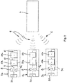
- a mobile computer unit 4 can be arranged within the range of several field devices and correspondingly several sensor or signal detection units 3a, 3b, 3c. Each of the units is provided with a respective transceiver unit 7a, 7b, 7c in order to enable wireless communication with the mobile computer unit 4.
- Each of the sensor or signal acquisition units 3a, 3b, 3c comprises a plurality of functional blocks 10a to 10n. This is also in Figure 2 indicated.
- the signals of the individual function blocks 10a to 10n are transmitted wirelessly to the mobile computer unit 4 via the respective transmitting / receiving units 7a, 7b, 7c.
- the calculation of the actual values and the setpoint-actual value comparison with regard to the function blocks are carried out in the mobile computer unit 4.
- the mobile computer unit 4 can also be used to intervene when an error is detected, that is to say either corrective action can be taken or the respective field device 2 can be completely switched off or brought into a safe state.
- the arrangement 1 is designed to provide permanent communication between the field device 2 and the mobile computer unit 4.
- a break in communication leads in particular to the output of an error signal. If necessary, in this case the field device can go into a predetermined safe state. If the mobile computer unit 4 is removed, it can also be provided that all field devices 2 actually in communication with it, which are addressed by the mobile computer unit 4, go into a defined state that is considered secured.
- circuit breakers that are in Fig. 2 are shown between the function blocks 10a to n
- changeover switches can also be provided between the function blocks, as in FIG Fig. 1 is shown, so that, for example, an i + 1-th block (0 ⁇ 1 ⁇ n) can optionally be connected to the i-th block or the receiving unit 7.
- the mobile computer unit 4 shown can also be provided with several mobile computer units 4 and used in conjunction with several field devices 2. In this way, the values determined by the respective mobile computer unit 4 can also be verified or redundancies can be created in order to further increase security.
- devices for encrypting the data and signals to be transmitted can be provided in the area of the respective transmitting / receiving units 7, 7a, 7b, 7c, 40, 41, 50.
- Such encryption devices make it possible to significantly increase the manipulation security of the field device or the field devices 2.
- a stimulus can be generated at the output of the field device 2 and the reaction of the control system 5 can be evaluated.
- the behavior of the measurement section from the field device 2 to the control system 5 is advantageously known, so that the response from the sensor or signal detection units 3a, 3b, 3c can be predicted.
- the predicted value is compared with the measured value. The amount of the possibly resulting difference between these values is a measure of the measuring accuracy of the sensor or signal detection units 3a, 3b, 3c.
- the behavior of the entire measurement path can also be checked by giving up the stimulus and corrective action taken if necessary or correction factors taken into account in calculations if there are deviations from predefinable setpoints.
- the determined or calculated values can be stored and available as reference values for statistical purposes and for subsequent measurements, calculations and evaluations.
- numerous others can be provided, each of which has at least one mobile computer unit for performing calculations and / or evaluations are provided and the sensor or signal acquisition unit and the mobile computer unit each comprise at least one device for wireless transmission and / or reception of data and / or signals for wireless communication with one another.
Landscapes
- Engineering & Computer Science (AREA)
- Physics & Mathematics (AREA)
- General Physics & Mathematics (AREA)
- Automation & Control Theory (AREA)
- General Engineering & Computer Science (AREA)
- Manufacturing & Machinery (AREA)
- Quality & Reliability (AREA)
- Computer Networks & Wireless Communication (AREA)
- Arrangements For Transmission Of Measured Signals (AREA)
Claims (5)
- Arrangement (1) destiné à la réalisation de mesures de niveau d'intégrité de sécurité dans une installation, comprenant au moins un appareil de terrain (2), au moins une unité de capteur ou de détection de signaux (3, 3a, 3b, 3c) associée ou pouvant être associée à celui-ci et présentant une partie capteur (30) et au moins un bloc de fonctions (10, 10a, 10n),arrangement pour lequel il est prévu au moins une unité de calcul mobile (4) destinée à effectuer des calculs et/ou des évaluations,l'au moins une unité de capteur ou de détection de signaux (3, 3a, 3b, 3c) et l'au moins une unité de calcul mobile (4) comprenant, pour la communication sans fil entre elles, chacune au moins un dispositif (7, 7a, 7b, 7c, 40) destiné à l'émission et à la réception sans fil de données et/ou de signaux,le dispositif (40) ou un autre dispositif (41) de l'unité de calcul mobile servant à la communication sans fil avec un système numérique de contrôle commande (5), lequel système numérique de contrôle commande (5) reçoit via une liaison filaire les valeurs mesurées actuelles de l'appareil de terrain et les transmet via une liaison sans fil à l'unité de calcul mobile (4),le dispositif (7, 7a, 7b, 7c) destiné à la transmission et à la réception sans fil de données et/ou de signaux de l'unité de capteur ou de détection de signaux (3, 3a, 3b, 3c) pouvant être connecté ou étant connecté à au moins un bloc de fonctions (10, 10a, 10n) et/ou à la partie capteur (30) de l'unité de capteur ou de détection de signaux (3, 3a, 3b, 3c) pour fournir un accès sans fil de l'unité de calcul mobile (4) au bloc de fonctions (10, 10a, 10n) et/ou à la partie capteur (30),caractériséen ce que l'unité de calcul mobile (4) est conçue pour calculer une valeur de mesure théorique à partir des données et/ou des signaux de l'unité de capteur ou de détection de signaux (3, 3a, 3b, 3c), ou une valeur réelle à partir des données et/ou des signaux des blocs de fonctions, pour comparer la valeur de mesure théorique ou la valeur réelle à la valeur de mesure actuelle ou à une valeur de consigne, et pour tirer des conclusions sur d'éventuelles erreurs dans la chaîne de transmission de signaux ou de mesure par le biais de la comparaison.
- Arrangement (1) selon la revendication 1,
caractérisé
en ce que l'unité de calcul mobile (4) comprend au moins un moyen d'affichage (42) et/ou au moins un moyen de stockage (43) et/ou au moins un équipement de connexion Internet sans fil. - Arrangement (1) selon l'une des revendications précédentes,
caractérisé
en ce qu'une transmission cryptée de données et/ou de signaux est prévue. - Procédé destiné à la réalisation de mesures de niveau d'intégrité de sécurité dans une installation, comprenant au moins deux appareils de terrain (2) avec au moins une unité de capteur ou de détection de signaux (3a, 3b, 3c) associée et au moins deux blocs de fonctions (10, 10n),
caractérisé en ce qu'un dispositif (7, 7a, 7b, 7c, 40) destiné à l'émission et à la réception sans fil transmet sans fil des données et/ou des signaux de l'unité de capteur ou de détection de signaux (3, 3a, 3b, 3c) ou des blocs de fonctions (10, 10n) à une unité de calcul mobile (4) en vue de la réalisation de calculs et/ou d'évaluations, le dispositif (40) ou un autre dispositif (41) de l'unité de calcul mobile, lequel dispositif est destiné à la communication sans fil, recevant via une liaison filaire des valeurs de mesure actuelles de l'appareil de terrain d'un système numérique de contrôle de commande (5) et les transmettant via une liaison sans fil à l'unité de calcul mobile (4), et l'unité de calcul mobile (4) calculant une valeur de mesure théorique ou une valeur réelle à partir des données et/ou des signaux de l'unité de capteur ou de détection de signaux (3, 3a, 3b, 3c) ou des blocs de fonctions (10, 10n), la compare à une valeur de mesure actuelle reçue via une liaison filaire (51) d'un système numérique de contrôle commande (5) ou à une valeur de consigne prédéfinissable ou prédéfinie, et tire des conclusions de la comparaison sur d'éventuelles erreurs dans la chaîne de transmission de signaux ou de mesure. - Procédé selon la revendication 4,
caractérisé
en ce que plusieurs appareils de terrain (2) sont disposés à portée de l'unité de calcul mobile (4) et reçoivent la fonctionnalité SIL via l'unité de calcul mobile (4).
Applications Claiming Priority (2)
| Application Number | Priority Date | Filing Date | Title |
|---|---|---|---|
| DE102012109227.3A DE102012109227A1 (de) | 2012-09-28 | 2012-09-28 | Anordnung, umfassend zumindest ein Feldgerät, zumindest eine diesem zugeordnete Sensor- oder Signalerfassungseinheit und zumindest einen Funktionsblock |
| PCT/EP2013/067790 WO2014048664A1 (fr) | 2012-09-28 | 2013-08-28 | Ensemble, comprenant au moins un appareil de terrain, au moins une unité à capteur ou une unité de détection de signal affectée à ce dernier, et au moins un bloc fonctionnel |
Publications (2)
| Publication Number | Publication Date |
|---|---|
| EP2901224A1 EP2901224A1 (fr) | 2015-08-05 |
| EP2901224B1 true EP2901224B1 (fr) | 2021-12-15 |
Family
ID=49115498
Family Applications (1)
| Application Number | Title | Priority Date | Filing Date |
|---|---|---|---|
| EP13756860.6A Active EP2901224B1 (fr) | 2012-09-28 | 2013-08-28 | Ensemble, comprenant au moins un appareil de terrain, au moins une unité à capteur ou une unité de détection de signal affectée à ce dernier, et au moins un bloc fonctionnel |
Country Status (5)
| Country | Link |
|---|---|
| US (1) | US20150254973A1 (fr) |
| EP (1) | EP2901224B1 (fr) |
| CN (1) | CN104685430B (fr) |
| DE (1) | DE102012109227A1 (fr) |
| WO (1) | WO2014048664A1 (fr) |
Families Citing this family (6)
| Publication number | Priority date | Publication date | Assignee | Title |
|---|---|---|---|---|
| DE102014111758A1 (de) * | 2014-08-18 | 2016-02-18 | Endress + Hauser Gmbh + Co. Kg | Verfahren zum Überprüfen eines Feldgerätes |
| AT518598A1 (de) * | 2016-05-10 | 2017-11-15 | Siemens Ag Oesterreich | Überwachen der Inbetriebnahme und der Plausibilität von Daten eines Leistungsmesssensors in einem Verteilernetz |
| DE102017219383A1 (de) * | 2017-10-27 | 2019-05-02 | Robert Bosch Gmbh | Verfahren zum Erfassen eines Zustandes eines Produkts und Verfahren zum Einrichten des Produkts und eines Datennetzwerks dafür |
| DE102018206382A1 (de) * | 2018-04-25 | 2019-10-31 | Robert Bosch Gmbh | Abschalteinrichtung für Komponenten in sicherheitskritischen Systemen |
| EP3745219B1 (fr) * | 2019-05-28 | 2023-07-05 | ABB Schweiz AG | Mise en service et surveillance d'état de procédés industriels au moyen d'un dispositif de détection sans fil |
| DE102020112811B3 (de) | 2020-05-12 | 2021-10-21 | Ebm-Papst Mulfingen Gmbh & Co. Kg | Verfahren und Anlage zur Authentifizierung wenigstens eines Aggregats |
Family Cites Families (10)
| Publication number | Priority date | Publication date | Assignee | Title |
|---|---|---|---|---|
| DE10162334A1 (de) * | 2001-12-18 | 2003-07-03 | Endress & Hauser Gmbh & Co Kg | Feldgerät und ein Verfahren zur Kalibrierung eines Feldgerätes |
| US7035773B2 (en) * | 2002-03-06 | 2006-04-25 | Fisher-Rosemount Systems, Inc. | Appendable system and devices for data acquisition, analysis and control |
| DE10253572A1 (de) * | 2002-11-15 | 2004-07-29 | Vega Grieshaber Kg | Drahtlose Kommunikation |
| DE10326665A1 (de) * | 2003-06-11 | 2005-01-20 | Endress + Hauser Process Solutions Ag | Verfahren zum Überwachen eines Feldgerätes |
| DE102004020393A1 (de) * | 2004-04-23 | 2005-11-10 | Endress + Hauser Gmbh + Co. Kg | Funkmodul für Feldgeräte der Automatisierungstechnik |
| US7529644B2 (en) * | 2004-08-31 | 2009-05-05 | Watlow Electric Manufacturing Company | Method of diagnosing an operations systems |
| DE102007022991A1 (de) * | 2007-05-15 | 2008-11-20 | Endress + Hauser Conducta Gesellschaft für Mess- und Regeltechnik mbH + Co. KG | Vorrichtung zur Signalüberwachung für einen zeitweiligen Einsatz in einem Feldgerät der Prozessautomatisierungstechnik |
| US8374094B2 (en) * | 2008-12-11 | 2013-02-12 | Fisher-Rosemount Systems, Inc | Methods and systems to verify a communication path between a field device and a process controller in a process control system |
| ES2420779T3 (es) * | 2009-04-20 | 2013-08-26 | Otis Elevator Company | Control de seguridad de transportador |
| US20100274528A1 (en) * | 2009-04-22 | 2010-10-28 | Rosemount Inc. | Field device with measurement accuracy reporting |
-
2012
- 2012-09-28 DE DE102012109227.3A patent/DE102012109227A1/de not_active Withdrawn
-
2013
- 2013-08-28 WO PCT/EP2013/067790 patent/WO2014048664A1/fr not_active Ceased
- 2013-08-28 EP EP13756860.6A patent/EP2901224B1/fr active Active
- 2013-08-28 CN CN201380050599.3A patent/CN104685430B/zh not_active Expired - Fee Related
- 2013-08-28 US US14/431,568 patent/US20150254973A1/en not_active Abandoned
Also Published As
| Publication number | Publication date |
|---|---|
| CN104685430B (zh) | 2018-04-27 |
| DE102012109227A1 (de) | 2014-04-03 |
| US20150254973A1 (en) | 2015-09-10 |
| CN104685430A (zh) | 2015-06-03 |
| DE102012109227A8 (de) | 2014-06-12 |
| EP2901224A1 (fr) | 2015-08-05 |
| WO2014048664A1 (fr) | 2014-04-03 |
Similar Documents
| Publication | Publication Date | Title |
|---|---|---|
| EP2901224B1 (fr) | Ensemble, comprenant au moins un appareil de terrain, au moins une unité à capteur ou une unité de détection de signal affectée à ce dernier, et au moins un bloc fonctionnel | |
| EP2984530B1 (fr) | Appareil d'alimentation d'un transducteur de mesure, système destiné à être utilisé dans les techniques d'automatisation, et procédé d'utilisation dudit système | |
| EP3069202B1 (fr) | Commande de sécurité à entrées configurables | |
| EP3383598B1 (fr) | Système manipulateur et procédé d'identification de dispositifs de commande | |
| DE202010016362U1 (de) | Anordnung mit einer übergeordneten Steuereinheit und zumindest einem mit der Steuereinheit verbindbaren intelligenten Feldgerät | |
| DE102007032715A1 (de) | System und Verfahren zur Überwachung des Datenverkehrs bei einem Feldbus | |
| DE102014105075A1 (de) | Verfahren und Kommunikationsanordnung zur Datenkommunikation | |
| EP3070556A1 (fr) | Procédé, dispositif de calcul, unité d'utilisateur et système de paramétrage d'un appareil électrique | |
| DE112008003195T5 (de) | Elektrischer Schaltkreis mit einem physikalischen Übertragungsschicht-Diagnosesystem | |
| EP3510453B1 (fr) | Procédé d'interaction de commande et dispositif de communication permettant d'effectuer une interaction de commande entre une commande électronique et un appareil de réglage | |
| EP2701019B1 (fr) | Procédé de paramétrage d'un appareil de terrain, appareil de terrain correspondant et système de paramétrage | |
| EP4168343B1 (fr) | Procédé de fonctionnement d'une installation de transport des personnes par configuration fiable d'un dispositif de sécurisation électronique au moyen d'une transmission visuelle de données | |
| DE112013002386T5 (de) | Einrichtung zum Überprüfen von Datenübertragungen auf zweidrahtigen, kombiniert verbundenen Energie- und Datennetzsystemen für eine Automatisierung | |
| WO2019096629A1 (fr) | Système de communication de la technique de l'automatisation et industrielle ainsi qu'unité d'aiguillage en y pour un tel système de communication | |
| WO2010040628A2 (fr) | Procédé pour tester le comportement d'une installation de traitement | |
| DE102017216677A1 (de) | Verfahren und Anordnung zum Bereitstellen eines Zugriffs auf mindestens ein Feldgerät einer technischen Anlage | |
| EP3741027B1 (fr) | Équipement à haute ou moyenne tension | |
| DE102010062670B4 (de) | Wartungseinheit für ein ASI-Bussystem sowie ASI-Bussystem | |
| DE102016119744A1 (de) | Verfahren und System zum Verhindern eines unerwünschten Zugriffs auf ein Feldgerät | |
| DE102016202749A1 (de) | Sicherheitsgerichtete Steuervorrichtung und Verfahren zum Betrieb einer sicherheitsgerichteten Steuervorrichtung | |
| DE102014208839A1 (de) | Verfahren zur sicheren Datenübertragung zwischen einer Automatisierungsanlage und einer IT-Komponente | |
| WO2019197443A1 (fr) | Module intermédiaire, module récepteur, système de surveillance et procédé de surveillance | |
| DE102019208314A1 (de) | Verfahren und System zur automatischen Absicherung eines mittels einer mobilen Bedienvorrichtung gesteuerten Betriebs eines Robotersystems | |
| DE202007019504U1 (de) | Gasdruckfeder mit Messmittel sowie Einrichtung zur Überwachung zumindest einer innerhalb und/oder an einer Gasruckfeder auftretenden physikalischen Messgröße | |
| EP3644143B1 (fr) | Ensemble périphérique à paramétrage automatique |
Legal Events
| Date | Code | Title | Description |
|---|---|---|---|
| PUAI | Public reference made under article 153(3) epc to a published international application that has entered the european phase |
Free format text: ORIGINAL CODE: 0009012 |
|
| 17P | Request for examination filed |
Effective date: 20150310 |
|
| AK | Designated contracting states |
Kind code of ref document: A1 Designated state(s): AL AT BE BG CH CY CZ DE DK EE ES FI FR GB GR HR HU IE IS IT LI LT LU LV MC MK MT NL NO PL PT RO RS SE SI SK SM TR |
|
| AX | Request for extension of the european patent |
Extension state: BA ME |
|
| DAX | Request for extension of the european patent (deleted) | ||
| STAA | Information on the status of an ep patent application or granted ep patent |
Free format text: STATUS: EXAMINATION IS IN PROGRESS |
|
| 17Q | First examination report despatched |
Effective date: 20171208 |
|
| RAP1 | Party data changed (applicant data changed or rights of an application transferred) |
Owner name: ENDRESS+HAUSER SE+CO. KG |
|
| GRAP | Despatch of communication of intention to grant a patent |
Free format text: ORIGINAL CODE: EPIDOSNIGR1 |
|
| STAA | Information on the status of an ep patent application or granted ep patent |
Free format text: STATUS: GRANT OF PATENT IS INTENDED |
|
| INTG | Intention to grant announced |
Effective date: 20210218 |
|
| GRAS | Grant fee paid |
Free format text: ORIGINAL CODE: EPIDOSNIGR3 |
|
| GRAJ | Information related to disapproval of communication of intention to grant by the applicant or resumption of examination proceedings by the epo deleted |
Free format text: ORIGINAL CODE: EPIDOSDIGR1 |
|
| GRAL | Information related to payment of fee for publishing/printing deleted |
Free format text: ORIGINAL CODE: EPIDOSDIGR3 |
|
| STAA | Information on the status of an ep patent application or granted ep patent |
Free format text: STATUS: EXAMINATION IS IN PROGRESS |
|
| INTC | Intention to grant announced (deleted) | ||
| GRAP | Despatch of communication of intention to grant a patent |
Free format text: ORIGINAL CODE: EPIDOSNIGR1 |
|
| STAA | Information on the status of an ep patent application or granted ep patent |
Free format text: STATUS: GRANT OF PATENT IS INTENDED |
|
| INTG | Intention to grant announced |
Effective date: 20210730 |
|
| GRAF | Information related to payment of grant fee modified |
Free format text: ORIGINAL CODE: EPIDOSCIGR3 |
|
| GRAA | (expected) grant |
Free format text: ORIGINAL CODE: 0009210 |
|
| STAA | Information on the status of an ep patent application or granted ep patent |
Free format text: STATUS: THE PATENT HAS BEEN GRANTED |
|
| AK | Designated contracting states |
Kind code of ref document: B1 Designated state(s): AL AT BE BG CH CY CZ DE DK EE ES FI FR GB GR HR HU IE IS IT LI LT LU LV MC MK MT NL NO PL PT RO RS SE SI SK SM TR |
|
| REG | Reference to a national code |
Ref country code: GB Ref legal event code: FG4D Free format text: NOT ENGLISH Ref country code: CH Ref legal event code: EP |
|
| REG | Reference to a national code |
Ref country code: IE Ref legal event code: FG4D Free format text: LANGUAGE OF EP DOCUMENT: GERMAN Ref country code: DE Ref legal event code: R096 Ref document number: 502013016018 Country of ref document: DE |
|
| REG | Reference to a national code |
Ref country code: AT Ref legal event code: REF Ref document number: 1455955 Country of ref document: AT Kind code of ref document: T Effective date: 20220115 |
|
| REG | Reference to a national code |
Ref country code: LT Ref legal event code: MG9D |
|
| REG | Reference to a national code |
Ref country code: NL Ref legal event code: MP Effective date: 20211215 |
|
| PG25 | Lapsed in a contracting state [announced via postgrant information from national office to epo] |
Ref country code: RS Free format text: LAPSE BECAUSE OF FAILURE TO SUBMIT A TRANSLATION OF THE DESCRIPTION OR TO PAY THE FEE WITHIN THE PRESCRIBED TIME-LIMIT Effective date: 20211215 Ref country code: LT Free format text: LAPSE BECAUSE OF FAILURE TO SUBMIT A TRANSLATION OF THE DESCRIPTION OR TO PAY THE FEE WITHIN THE PRESCRIBED TIME-LIMIT Effective date: 20211215 Ref country code: FI Free format text: LAPSE BECAUSE OF FAILURE TO SUBMIT A TRANSLATION OF THE DESCRIPTION OR TO PAY THE FEE WITHIN THE PRESCRIBED TIME-LIMIT Effective date: 20211215 Ref country code: BG Free format text: LAPSE BECAUSE OF FAILURE TO SUBMIT A TRANSLATION OF THE DESCRIPTION OR TO PAY THE FEE WITHIN THE PRESCRIBED TIME-LIMIT Effective date: 20220315 |
|
| PG25 | Lapsed in a contracting state [announced via postgrant information from national office to epo] |
Ref country code: SE Free format text: LAPSE BECAUSE OF FAILURE TO SUBMIT A TRANSLATION OF THE DESCRIPTION OR TO PAY THE FEE WITHIN THE PRESCRIBED TIME-LIMIT Effective date: 20211215 Ref country code: NO Free format text: LAPSE BECAUSE OF FAILURE TO SUBMIT A TRANSLATION OF THE DESCRIPTION OR TO PAY THE FEE WITHIN THE PRESCRIBED TIME-LIMIT Effective date: 20220315 Ref country code: LV Free format text: LAPSE BECAUSE OF FAILURE TO SUBMIT A TRANSLATION OF THE DESCRIPTION OR TO PAY THE FEE WITHIN THE PRESCRIBED TIME-LIMIT Effective date: 20211215 Ref country code: HR Free format text: LAPSE BECAUSE OF FAILURE TO SUBMIT A TRANSLATION OF THE DESCRIPTION OR TO PAY THE FEE WITHIN THE PRESCRIBED TIME-LIMIT Effective date: 20211215 Ref country code: GR Free format text: LAPSE BECAUSE OF FAILURE TO SUBMIT A TRANSLATION OF THE DESCRIPTION OR TO PAY THE FEE WITHIN THE PRESCRIBED TIME-LIMIT Effective date: 20220316 |
|
| PG25 | Lapsed in a contracting state [announced via postgrant information from national office to epo] |
Ref country code: NL Free format text: LAPSE BECAUSE OF FAILURE TO SUBMIT A TRANSLATION OF THE DESCRIPTION OR TO PAY THE FEE WITHIN THE PRESCRIBED TIME-LIMIT Effective date: 20211215 |
|
| PG25 | Lapsed in a contracting state [announced via postgrant information from national office to epo] |
Ref country code: SM Free format text: LAPSE BECAUSE OF FAILURE TO SUBMIT A TRANSLATION OF THE DESCRIPTION OR TO PAY THE FEE WITHIN THE PRESCRIBED TIME-LIMIT Effective date: 20211215 Ref country code: SK Free format text: LAPSE BECAUSE OF FAILURE TO SUBMIT A TRANSLATION OF THE DESCRIPTION OR TO PAY THE FEE WITHIN THE PRESCRIBED TIME-LIMIT Effective date: 20211215 Ref country code: RO Free format text: LAPSE BECAUSE OF FAILURE TO SUBMIT A TRANSLATION OF THE DESCRIPTION OR TO PAY THE FEE WITHIN THE PRESCRIBED TIME-LIMIT Effective date: 20211215 Ref country code: PT Free format text: LAPSE BECAUSE OF FAILURE TO SUBMIT A TRANSLATION OF THE DESCRIPTION OR TO PAY THE FEE WITHIN THE PRESCRIBED TIME-LIMIT Effective date: 20220418 Ref country code: ES Free format text: LAPSE BECAUSE OF FAILURE TO SUBMIT A TRANSLATION OF THE DESCRIPTION OR TO PAY THE FEE WITHIN THE PRESCRIBED TIME-LIMIT Effective date: 20211215 Ref country code: EE Free format text: LAPSE BECAUSE OF FAILURE TO SUBMIT A TRANSLATION OF THE DESCRIPTION OR TO PAY THE FEE WITHIN THE PRESCRIBED TIME-LIMIT Effective date: 20211215 Ref country code: CZ Free format text: LAPSE BECAUSE OF FAILURE TO SUBMIT A TRANSLATION OF THE DESCRIPTION OR TO PAY THE FEE WITHIN THE PRESCRIBED TIME-LIMIT Effective date: 20211215 |
|
| PG25 | Lapsed in a contracting state [announced via postgrant information from national office to epo] |
Ref country code: PL Free format text: LAPSE BECAUSE OF FAILURE TO SUBMIT A TRANSLATION OF THE DESCRIPTION OR TO PAY THE FEE WITHIN THE PRESCRIBED TIME-LIMIT Effective date: 20211215 |
|
| REG | Reference to a national code |
Ref country code: DE Ref legal event code: R097 Ref document number: 502013016018 Country of ref document: DE |
|
| PG25 | Lapsed in a contracting state [announced via postgrant information from national office to epo] |
Ref country code: IS Free format text: LAPSE BECAUSE OF FAILURE TO SUBMIT A TRANSLATION OF THE DESCRIPTION OR TO PAY THE FEE WITHIN THE PRESCRIBED TIME-LIMIT Effective date: 20220415 |
|
| PLBE | No opposition filed within time limit |
Free format text: ORIGINAL CODE: 0009261 |
|
| STAA | Information on the status of an ep patent application or granted ep patent |
Free format text: STATUS: NO OPPOSITION FILED WITHIN TIME LIMIT |
|
| PG25 | Lapsed in a contracting state [announced via postgrant information from national office to epo] |
Ref country code: DK Free format text: LAPSE BECAUSE OF FAILURE TO SUBMIT A TRANSLATION OF THE DESCRIPTION OR TO PAY THE FEE WITHIN THE PRESCRIBED TIME-LIMIT Effective date: 20211215 Ref country code: AL Free format text: LAPSE BECAUSE OF FAILURE TO SUBMIT A TRANSLATION OF THE DESCRIPTION OR TO PAY THE FEE WITHIN THE PRESCRIBED TIME-LIMIT Effective date: 20211215 |
|
| 26N | No opposition filed |
Effective date: 20220916 |
|
| PG25 | Lapsed in a contracting state [announced via postgrant information from national office to epo] |
Ref country code: SI Free format text: LAPSE BECAUSE OF FAILURE TO SUBMIT A TRANSLATION OF THE DESCRIPTION OR TO PAY THE FEE WITHIN THE PRESCRIBED TIME-LIMIT Effective date: 20211215 |
|
| PG25 | Lapsed in a contracting state [announced via postgrant information from national office to epo] |
Ref country code: MC Free format text: LAPSE BECAUSE OF FAILURE TO SUBMIT A TRANSLATION OF THE DESCRIPTION OR TO PAY THE FEE WITHIN THE PRESCRIBED TIME-LIMIT Effective date: 20211215 |
|
| REG | Reference to a national code |
Ref country code: CH Ref legal event code: PL |
|
| GBPC | Gb: european patent ceased through non-payment of renewal fee |
Effective date: 20220828 |
|
| PG25 | Lapsed in a contracting state [announced via postgrant information from national office to epo] |
Ref country code: LU Free format text: LAPSE BECAUSE OF NON-PAYMENT OF DUE FEES Effective date: 20220828 Ref country code: LI Free format text: LAPSE BECAUSE OF NON-PAYMENT OF DUE FEES Effective date: 20220831 Ref country code: CH Free format text: LAPSE BECAUSE OF NON-PAYMENT OF DUE FEES Effective date: 20220831 |
|
| REG | Reference to a national code |
Ref country code: BE Ref legal event code: MM Effective date: 20220831 |
|
| PG25 | Lapsed in a contracting state [announced via postgrant information from national office to epo] |
Ref country code: IT Free format text: LAPSE BECAUSE OF FAILURE TO SUBMIT A TRANSLATION OF THE DESCRIPTION OR TO PAY THE FEE WITHIN THE PRESCRIBED TIME-LIMIT Effective date: 20211215 |
|
| P01 | Opt-out of the competence of the unified patent court (upc) registered |
Effective date: 20230601 |
|
| PG25 | Lapsed in a contracting state [announced via postgrant information from national office to epo] |
Ref country code: IE Free format text: LAPSE BECAUSE OF NON-PAYMENT OF DUE FEES Effective date: 20220828 Ref country code: FR Free format text: LAPSE BECAUSE OF NON-PAYMENT OF DUE FEES Effective date: 20220831 |
|
| PG25 | Lapsed in a contracting state [announced via postgrant information from national office to epo] |
Ref country code: BE Free format text: LAPSE BECAUSE OF NON-PAYMENT OF DUE FEES Effective date: 20220831 |
|
| REG | Reference to a national code |
Ref country code: AT Ref legal event code: MM01 Ref document number: 1455955 Country of ref document: AT Kind code of ref document: T Effective date: 20220828 |
|
| PG25 | Lapsed in a contracting state [announced via postgrant information from national office to epo] |
Ref country code: GB Free format text: LAPSE BECAUSE OF NON-PAYMENT OF DUE FEES Effective date: 20220828 Ref country code: AT Free format text: LAPSE BECAUSE OF NON-PAYMENT OF DUE FEES Effective date: 20220828 |
|
| PG25 | Lapsed in a contracting state [announced via postgrant information from national office to epo] |
Ref country code: HU Free format text: LAPSE BECAUSE OF FAILURE TO SUBMIT A TRANSLATION OF THE DESCRIPTION OR TO PAY THE FEE WITHIN THE PRESCRIBED TIME-LIMIT; INVALID AB INITIO Effective date: 20130828 |
|
| PG25 | Lapsed in a contracting state [announced via postgrant information from national office to epo] |
Ref country code: CY Free format text: LAPSE BECAUSE OF FAILURE TO SUBMIT A TRANSLATION OF THE DESCRIPTION OR TO PAY THE FEE WITHIN THE PRESCRIBED TIME-LIMIT Effective date: 20211215 |
|
| PG25 | Lapsed in a contracting state [announced via postgrant information from national office to epo] |
Ref country code: MK Free format text: LAPSE BECAUSE OF FAILURE TO SUBMIT A TRANSLATION OF THE DESCRIPTION OR TO PAY THE FEE WITHIN THE PRESCRIBED TIME-LIMIT Effective date: 20211215 |
|
| PG25 | Lapsed in a contracting state [announced via postgrant information from national office to epo] |
Ref country code: TR Free format text: LAPSE BECAUSE OF FAILURE TO SUBMIT A TRANSLATION OF THE DESCRIPTION OR TO PAY THE FEE WITHIN THE PRESCRIBED TIME-LIMIT Effective date: 20211215 |
|
| PG25 | Lapsed in a contracting state [announced via postgrant information from national office to epo] |
Ref country code: MT Free format text: LAPSE BECAUSE OF FAILURE TO SUBMIT A TRANSLATION OF THE DESCRIPTION OR TO PAY THE FEE WITHIN THE PRESCRIBED TIME-LIMIT Effective date: 20211215 |
|
| PGFP | Annual fee paid to national office [announced via postgrant information from national office to epo] |
Ref country code: DE Payment date: 20250820 Year of fee payment: 13 |