EP2901732B1 - Mécanisme permettant d'établir une connexion de réseau de données à commutation par paquets avec de multiples adresses ip - Google Patents
Mécanisme permettant d'établir une connexion de réseau de données à commutation par paquets avec de multiples adresses ip Download PDFInfo
- Publication number
- EP2901732B1 EP2901732B1 EP12769397.6A EP12769397A EP2901732B1 EP 2901732 B1 EP2901732 B1 EP 2901732B1 EP 12769397 A EP12769397 A EP 12769397A EP 2901732 B1 EP2901732 B1 EP 2901732B1
- Authority
- EP
- European Patent Office
- Prior art keywords
- network
- communication
- communication network
- internet protocol
- terminating point
- Prior art date
- Legal status (The legal status is an assumption and is not a legal conclusion. Google has not performed a legal analysis and makes no representation as to the accuracy of the status listed.)
- Not-in-force
Links
- 230000007246 mechanism Effects 0.000 title description 16
- 238000004891 communication Methods 0.000 claims description 172
- 238000012545 processing Methods 0.000 claims description 66
- 230000010267 cellular communication Effects 0.000 claims description 45
- 238000000034 method Methods 0.000 claims description 43
- 230000011664 signaling Effects 0.000 claims description 27
- 230000006870 function Effects 0.000 claims description 23
- 238000004590 computer program Methods 0.000 claims description 13
- 238000013507 mapping Methods 0.000 claims description 12
- 230000005540 biological transmission Effects 0.000 claims description 9
- 230000001413 cellular effect Effects 0.000 claims description 8
- 230000007774 longterm Effects 0.000 claims description 5
- 238000002360 preparation method Methods 0.000 claims description 3
- 230000008569 process Effects 0.000 claims description 3
- 238000005516 engineering process Methods 0.000 description 12
- 238000010586 diagram Methods 0.000 description 10
- 238000013459 approach Methods 0.000 description 5
- 230000004913 activation Effects 0.000 description 3
- 238000007689 inspection Methods 0.000 description 3
- 230000008859 change Effects 0.000 description 2
- 230000000052 comparative effect Effects 0.000 description 2
- 230000006835 compression Effects 0.000 description 2
- 238000007906 compression Methods 0.000 description 2
- 230000001419 dependent effect Effects 0.000 description 2
- 230000008571 general function Effects 0.000 description 2
- 239000004065 semiconductor Substances 0.000 description 2
- 238000000926 separation method Methods 0.000 description 2
- 230000003213 activating effect Effects 0.000 description 1
- 238000003491 array Methods 0.000 description 1
- 238000013475 authorization Methods 0.000 description 1
- 230000000295 complement effect Effects 0.000 description 1
- 238000007796 conventional method Methods 0.000 description 1
- 230000003247 decreasing effect Effects 0.000 description 1
- 238000011161 development Methods 0.000 description 1
- 230000018109 developmental process Effects 0.000 description 1
- 230000004069 differentiation Effects 0.000 description 1
- 230000000694 effects Effects 0.000 description 1
- 230000010354 integration Effects 0.000 description 1
- 238000002955 isolation Methods 0.000 description 1
- 229910044991 metal oxide Inorganic materials 0.000 description 1
- 150000004706 metal oxides Chemical class 0.000 description 1
- 238000010295 mobile communication Methods 0.000 description 1
- 238000012986 modification Methods 0.000 description 1
- 230000004048 modification Effects 0.000 description 1
- 238000012544 monitoring process Methods 0.000 description 1
- 238000001228 spectrum Methods 0.000 description 1
- 238000010561 standard procedure Methods 0.000 description 1
- 238000012546 transfer Methods 0.000 description 1
- 230000000007 visual effect Effects 0.000 description 1
Images



Classifications
-
- H—ELECTRICITY
- H04—ELECTRIC COMMUNICATION TECHNIQUE
- H04W—WIRELESS COMMUNICATION NETWORKS
- H04W76/00—Connection management
- H04W76/10—Connection setup
-
- H—ELECTRICITY
- H04—ELECTRIC COMMUNICATION TECHNIQUE
- H04W—WIRELESS COMMUNICATION NETWORKS
- H04W76/00—Connection management
- H04W76/10—Connection setup
- H04W76/12—Setup of transport tunnels
-
- H—ELECTRICITY
- H04—ELECTRIC COMMUNICATION TECHNIQUE
- H04L—TRANSMISSION OF DIGITAL INFORMATION, e.g. TELEGRAPHIC COMMUNICATION
- H04L69/00—Network arrangements, protocols or services independent of the application payload and not provided for in the other groups of this subclass
- H04L69/16—Implementation or adaptation of Internet protocol [IP], of transmission control protocol [TCP] or of user datagram protocol [UDP]
- H04L69/167—Adaptation for transition between two IP versions, e.g. between IPv4 and IPv6
-
- H—ELECTRICITY
- H04—ELECTRIC COMMUNICATION TECHNIQUE
- H04L—TRANSMISSION OF DIGITAL INFORMATION, e.g. TELEGRAPHIC COMMUNICATION
- H04L61/00—Network arrangements, protocols or services for addressing or naming
- H04L61/50—Address allocation
- H04L61/5007—Internet protocol [IP] addresses
-
- H—ELECTRICITY
- H04—ELECTRIC COMMUNICATION TECHNIQUE
- H04W—WIRELESS COMMUNICATION NETWORKS
- H04W76/00—Connection management
- H04W76/10—Connection setup
- H04W76/11—Allocation or use of connection identifiers
Definitions
- the present invention relates to a mechanism for establishing a packet data network connection provided with plural IP addresses.
- the present invention is related to an apparatus, a method and a computer program product which enable to add multiple IP addresses, such as multiple IPv6 prefixes, into a single PDN connection, and to break out IP links from network elements being different to a packet data network gateway or the like.
- communication networks e.g. of wire based communication networks, such as the Integrated Services Digital Network (ISDN), DSL, or wireless communication networks, such as the cdma2000 (code division multiple access) system, cellular 3rd generation (3G) and fourth generation (4G) communication networks like the Universal Mobile Telecommunications System (UMTS), enhanced communication networks based e.g.
- ISDN Integrated Services Digital Network
- DSL wireless communication networks
- cdma2000 (code division multiple access) system e.g., cellular 3rd generation (3G) and fourth generation (4G) communication networks like the Universal Mobile Telecommunications System (UMTS)
- UMTS Universal Mobile Telecommunications System
- cellular 2nd generation (2G) communication networks like the Global System for Mobile communications (GSM), the General Packet Radio System (GPRS), the Enhanced Data Rates for Global Evolution (EDGE), or other wireless communication system, such as the Wireless Local Area Network (WLAN), Bluetooth or Worldwide Interoperability for Microwave Access (WiMAX), took place all over the world.
- GSM Global System for Mobile communications
- GPRS General Packet Radio System
- EDGE Enhanced Data Rates for Global Evolution
- WLAN Wireless Local Area Network
- WiMAX Worldwide Interoperability for Microwave Access
- 3GPP 3rd Generation Partnership Project
- Telecoms & Internet converged Services & Protocols for Advanced Networks TISPAN
- ITU International Telecommunication Union
- 3GPP2 3rd Generation Partnership Project 2
- IETF Internet Engineering Task Force
- IEEE Institute of Electrical and Electronics Engineers
- terminal devices such as a user equipment (UE) and another communication network element or user equipment, a database, a server, etc.
- intermediate network elements such as communication network control elements, such as base transceiver stations, control nodes, support nodes or service nodes are involved which may belong to different communication network.
- the ability to communicate not only via one communication network, such as a cellular communication network of which the user of an UE is subscriber, but also via other communication networks having e.g. an IP based access, such as a WLAN or the like, is a common demand.
- IP connectivity between the mobile device and the network is realized using a point-to-point mimicking link, where the mobile device is assigned with a single /32 IPv4 address and/or a single /64 IPv6 prefix on a single network interface. For a new IP address, an additional connection between the mobile device and the network has to be created, essentially turning the mobile device to a multi-homed host.
- EPS 3GPP Evolved Packet System
- Each connection and a connectivity service is always identified by an APN, which in practice names a gateway node such as the PGW providing access to an external Packet Data Networks (PDN), such as the Internet or an (local) operator services network.
- PDN Packet Data Networks
- the gateway node is located in the mobile operator core network (home or visited) and anchors the mobile device and its connection both mobility and IP topology wise.
- the gateway node also has the function of the first-hop router for the mobile device.
- the present connectivity model is working properly in particular when IPv4 was the only realistic IP version and mobile devices were feature phones with a single radio access technology, a limited openness to IP stack for applications and a top down approach for IP connectivity.
- Applications control the activation of network resources and have a build-in knowledge of what kind of network access they needed (APNs, IP versions and alike).
- Document US 2008/285492 A1 discloses a method, apparatus and system for acquiring an access point name for an application employing a local Internet protocol breakout service.
- the apparatus includes a user management subsystem configured to initiate an Internet protocol application.
- the apparatus also includes a local breakout service monitoring subsystem configured to monitor availability of a local Internet protocol local breakout service and to obtain an access point name from the local Internet protocol local breakout service when the local Internet protocol local breakout service is available.
- the apparatus also includes an access point name selection control subsystem configured to bind the access point name to the Internet protocol application.
- Document US 2011/176531 A1 discloses methods and devices for handling local breakout traffic in a home base station, usable for transportation of traffic in conjunction with the home base station.
- Traffic arriving in the home base station from a mobile terminal connected to the home base station can be transported by means of local breakout transportation, which implies that the traffic is forwarded to a local node over a local network or to the Internet without passing a core network of a mobile telecommunications system.
- a local breakout bearer is established, which is a radio bearer that extends between the mobile terminal and the home base station. The mobile terminal forwards uplink traffic that is to be subject to local breakout transportation to the home base station on the local breakout bearer. Thus it is not required for traffic that is destined for local nodes or the Internet to pass the core network.
- a computer program product for a computer comprising software code portions for performing the steps of the above defined methods, when said product is run on the computer.
- the computer program product may comprise a computer-readable medium on which said software code portions are stored.
- the computer program product may be directly loadable into the internal memory of the computer and/or transmittable via a network by means of at least one of upload, download and push procedures.
- some examples of embodiments of the invention are advantageous for so-called split-UE scenarios, such as USB dongles, MiFi (My-WiFi) equipment, or even for implementations where a handset is internally architectured as split-UE (separated mobile terminal and terminal equipment), since the usage of e.g. EUI-64 link-layer address is suitable for such a scenario.
- an efficient traffic identification and separation is possible at the communication network control element, such as an access controller or eNB, since an identification/categorization of the connection to be established into one where a breakout connection is to be established or one which concerns another network element (and hence the connection parameters are to be forwarded to it) can be done with minimal processing load. For example, since no IP lookup or inspection is required on the eNB side, the impact on the eNB implementation is kept small.
- the load for the remaining network elements can be kept small.
- the rest of the 3GPP system such as CN elements like gateway nodes and MME is not involved. That is, the breakout IP link is local to eNB.
- the load for the system can be kept small.
- the local prefix at the SGW can be seen as mobility management less prefix without burden of PCC and other handover signaling.
- an operator can decide which network element is to be preferred as a terminating point for a breakout connection.
- a basic system architecture of a communication network where examples of embodiments of the invention are applicable may comprise a commonly known architecture of one or more communication systems comprising a wired or wireless access network subsystem and a core network.
- Such an architecture may comprise one or more access network control elements, radio access network elements, access service network gateways or base transceiver stations, such as a base station or eNB, which control a coverage area also referred to as a cell and with which one or more communication elements or terminal devices such as a UE or another device having a similar function, such as a modem chipset, a chip, a module etc., which can also be part of a UE or attached as a separate element to a UE, or the like, are capable to communicate via one or more channels for transmitting several types of data.
- core network elements such as gateway network elements, policy and charging control network elements, mobility management entities and the like may be comprised.
- nodes or network elements may comprise several means and components (not shown) which are required for control, processing and communication/signaling functionality.
- Such means may comprise, for example, one or more processor units including one or more processing portions for executing instructions, programs and for processing data, memory means for storing instructions, programs and data, for serving as a work area of the processor or processing portion and the like (e.g.
- processing portions should not be only considered to represent physical portions of one or more processors, but may also be considered as a logical division of the referred processing tasks performed by one or more processors.
- APNs are used to identify connections.
- APNs are used to identify connections.
- the use of APNs has turned out to be conceptually challenging for bottom up IP connectivity, since applications have less control on activating network connectivity. That is, enabling services and access isolation using multiple network connections has a cost.
- each 3GPP bearer and connection consumes both radio network and CN resources that are typically a subject to licensing.
- An equivalent functionality could be accomplished by just allowing multiple addresses (beyond dual-stack) on a single network interface.
- shortcuts or breakout connections e.g. to the Internet for certain IP traffic bypassing parts of the operator infrastructure.
- one approach is to use multiple interfaces, which in cellular only access case leads, for example, to an activation of a specialized bearer.
- a specialized bearer examples for such an approach are e.g. LIPA or SIPTO bearer for IP traffic.
- Other approaches according to comparative examples require, for example, multiple RABs, additional signaling, and the involvement of management elements such as MME/SGSN for providing truly local addresses that come from e.g. the eNB.
- MME/SGSN management elements
- support of multiple parallel PDN connections to different APNs requires also complex processing on the UE side, for example due to provisioning and connection management.
- measures like IP packet inspection at the eNB/SGW level are necessary, which leads to a decreased performance.
- the conventional methods require to establish a new default bearer, which is costly.
- a new bearer and connectivity model is implemented, which advocates multiple addressing on a single PDN network connection.
- the usage of multiple APNs can be avoided or at least reduced.
- a new link type for e.g. 3GPP based communication is provided which essentially replaces the conventional point-to-point link into a Non-Broadcast Multiple Access (NBMA) resembling link that allows for multiple exit or terminating points for IP connections in the operator IP network infrastructure.
- NBMA Non-Broadcast Multiple Access
- the proposed bearer and connectivity model is referred to as a multi-address bearer (also referred to as manifold bearer).
- the multi-address bearer is implemented, for example, in the 3GPP EPS , wherein traffic offloading from the 3GPP network is one goal.
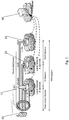
- FIG. 1 a diagram illustrating a general configuration of a communication network is shown where examples of embodiments of the invention are implemented, wherein the basic structure of the multi-address bearer (or manifold bearer) is illustrated. It is to be noted that the configuration shown in Fig. 1 shows only those devices, network elements and parts which are useful for understanding principles underlying the examples of embodiments of the invention. As also known by those skilled in the art there may be several other network elements or devices involved in a communication between the communication device (UE) and the network which are omitted here for the sake of simplicity.
- UE communication device
- Fig. 1 a communication network configuration is illustrated in which examples of embodiments of the invention are implementable.
- the network according to Fig. 1 is for example based on 3GPP EPS specifications. It is to be noted that the general functions of the elements described in connection with Fig. 1 as well as of reference points/interfaces there between are known to those skilled in the art so that a detailed description thereof is omitted here for the sake of simplicity.
- a communication element or UE 30 establishes a multi-address bearer to communicate with a cellular communication network comprising, for example, a communication network control element like a eNB 10 providing a radio access for the UE 30 to the network, a serving gateway element such as an SGW 20, and a packet data network gateway element such as a PGW 40.
- a communication network control element like a eNB 10 providing a radio access for the UE 30 to the network
- a serving gateway element such as an SGW 20
- a packet data network gateway element such as a PGW 40.
- certain types of EPS bearers are established, such as radio access bearers, S1 bearers, and S5/S8 bearers.
- IP links indicated by dashed arrows in Fig. 1
- the Internet i.e.
- a server 60 or the like) or to local networks and services can be established, wherein the eNB 10, the SGW 20 and the PGW 40 are usable as corresponding terminating or exit points for traffic which is received from and forwarded to the radio access (RA) towards the UE 30.
- RA radio access
- the multi-address bearer model as indicated in Fig. 1 is incremental to the existing 3GPP EPS structure with a fallback possibility to bearer types available in the current EPS.
- the multi-address bearer connection scheme is usable with IPv6, for example, since IPv6 is especially designed for multi-addressing.
- IPv4 addressing and links can be used in parallel to the bearer and connectivity model provided by the multi-address bearer.
- multiple addresses such as IPv6 prefixes are added into a single PDN Connection.
- These additional prefixes originate from one of the network elements of the communication network, such as from the eNB 10 or the SGW 20, and establish an IP based connection to another network such a local network or the Internet.
- an activation of multiple default bearers and E-RABs is avoided while multiple IPv6 prefixes over a single PDN connection are enabled.
- the additional prefixes are not supposed to be routed to the PGW (as a conventional exit point to external or other networks such as the Internet), but corresponding IP links are leaked/broken out as breakout connections at an "earlier" point in the network (e.g. from the radio access network).
- the identification of IP flows is performed without inspecting the IP layer but lower layer identifiers (e.g. link layer, described later) which allows for a better forwarding performance.
- a solution is used which is based on a convergence protocol signaling.
- the Packet Data Convergence Protocol (PDCP) is used which operates between the UE 30 and the eNB 10.
- PDCP is one the layers of the radio traffic stack in 3GPP based networks and performs, amongst others, IP header compression and a transfer of user data.
- a PDCP header consists of two fields: PID for compression protocol type indication and PDU Type.
- certain PDU type codes are used. According to the PDCP specification, there are several unused PDU types which are usable for this purpose.
- PDU types are commonly in use.
- several further of the remaining PDU types are reserved for the multi-address bearer purposes.
- one PDU type is used for the eNB terminated/breakout traffic
- one other PDU type is used for the SGW terminated/breakout traffic.
- a PDU type is used, according to some examples of embodiments of the invention, for multicast traffic where the breakout connection is established at more than one element, e.g. at two or all three of the eNB, the SGW and the PGW. It is to be noted that for PGW only terminated traffic an existing PDCP PDU type number is used. By means of this, it is possible to be conservative on the E-RAB level.
- one additional bearer pair i.e. a S1-U and S1-MME bearer pair between the eNB 10 and the SGW 20 on one side and the eNB 10 and an MME on the other side, is required in order to represent the SGW terminated/breakout traffic.
- a fair compromise is achieved with regard to the saved E-RAB consumption.
- the rest of the packet core network can be kept unaware of the multi-address bearer activities on the eNB site. Thus, the overall signaling load can be reduced.
- the communication network control element such as the eNB 10
- the communication network control element is able to make traffic differentiation for local consumption (i.e. breakout at the eNB) or for forwarding to bearers heading to further network elements (i.e. no breakout at least at the eNB), such as to the PGW 40 and the SGW 20, entirely without an IP lookup.
- PDCP also implicitly differentiates between data and control packets, which is useful according to some examples of embodiments of the invention during the configuration of the multi-address bearer.
- Link-layer addressing facilitates the integration of IPv6 from the mobile device IP stack point of view, since IPv6 was designed to work best over multicast link with link-layer addressing.
- the indication element such as the PDCP PDU type codes (e.g. for data packets) are mapped to link-layer addresses.
- a common conceptual link-layer addressing scheme is applied for a UE, an eNB, an SGW and a PGW.
- the link-layer addressing is not related to a real physical layer-2 address of each host on the multi-address link.
- the purpose of link layer addressing is to allow for an easier mapping of IP flows and IPv6 prefixes to the proper PDCP PDU types and radio level constructs.
- the link-layer is a conceptual construct with a known name space where the address implicitly contains the information of the network node (e.g. eNB, SGW) where the traffic is to be terminated.
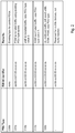
- Fig. 2 shows a diagram illustrating an example of a link-layer address mapping to PDCP PDU types. Specifically, Fig. 2 shows, according to some examples of embodiments of the invention, a mapping of PDCP PDU types to EUI-64 identifiers.
- a PDU type "000b” is assumed to represent the existing type for control PDUs, i.e. one of the already used types.
- a PDU type "001b” is allocated to IP traffic to be terminated at the PGW (also referred to as PDU type 1), wherein the EUI-64 identifier mapped to this PDU type is optional.
- PDU type "010b” is allocated to IP traffic to be terminated at the eNB (also referred to as PDU type 2).
- PDU type "011b” is allocated to IP traffic to be terminated at the SGW (also referred to as PDU type 3).
- the PDU type "100b" is allocated to an UL multicast traffic handling. That is, when the eNB 10 receives traffic using this PDU type "100b", for example, it knows that the IP packet inside the PDCP PDU is to be copied and forwarded also to connections towards the SGW 20 (if available) and the PGW 40. According to some examples of embodiments of the invention, whether the PDU type "100b" is used is a decision of the UE 30, since it can also do copying of the multicast packets to each receiver (eNB, SGW and PGW).
- Fig. 3 shows a diagram illustrating further details of a communication network configuration where some examples of embodiments of the invention are implemented. Specifically, Fig. 3 illustrates the results of the procedures related to the mapping of the PDU types, the different bearers and the conceptual link-layer addresses (i.e. LLAs) as described above.
- the LLAs are "conceptual" in a sense that they are just for easing the internal operations of the IP stack in the UE. According to some examples of embodiments of the invention, the LLAs are not physically installed on any device since 3GPP link model (old and the new one) does not have real physical link-layer addresses.
- the communication connection via the multi-address bearer is established between the UE 30 and the network.
- the UE 30 mobile device
- the UE 30 has an interface with multiple prefixes, wherein in the illustrated example three LLAs 1 to 3 are provided. That is, according to some examples of embodiments of the invention, a multi-address bearer is shown inside the UE as an internal interface with multiple prefix.
- each prefix i.e. breakout point or LLA_x according to Fig. 3
- each prefix is presented as an individual interface inside the UE.
- the eNB 10 forms the access node to the communication network, wherein the connection to the UE 30 is provided via a (single) E-RAB (RABx in Fig. 3 ).
- the SGW 20 is connected to the eNB 10 via respective S1-U bearers.
- An IP based link using a prefix B and mapped on PDU type code 3 which is mapped to LLA 3 is broken out at the SGW 20, that is the SGW 20 is terminating point for the breakout connection of the IP link based on prefix B.
- an MME 50 is shown which is connected to the eNB 10 via an S1 MME interface, and to the SGW 20 via an S11 interface.
- S1 MME Session Initiation Protocol
- S1-U bearer 2 and S1 MME a corresponding bearer pair
- the PGW 40 is connected to the SGW 20 via respective S5/S8 bearers.
- An IP based link using a prefix C and mapped on PDU type code 1 which is mapped to LLA 3 is formed via the SGW 20 e.g. according to standard procedure.
- the multi-address bearer indicated in Figs. 1 and 3 is modeled as an isolated per mobile device link. That is, according to some examples of embodiments of the invention, there is only one end host attached to the multi-address link in addition to routers. According to some further examples of embodiments of the invention, however, the end host (i.e. the UE) shares the addresses from the multi-address link to another network, for example a local area network (i.e. performs a procedure known as tethering).
- a local area network i.e. performs a procedure known as tethering
- the SGW and PGW entities are combined into a so-called SAE gateway node.
- the terminating or breakout point to be formed by the SGW functionality and the router is in the same place as the PGW.
- the connection establishment procedure according to some examples of embodiments of the invention using the multi-address bearer and an indication that the SGW shall form a terminating point for the breakout connection, a difference is the mobility management is provided. That is, the IPv6 prefix provided via the "SGW router" does not provide mobility or any other features that are typically associated with a 3GPP PDN Connections and EPS bearer, such as policy control. It is just for a plain simple IP use.
- the operator it is possible for the operator to configure the communication in such a manner that not only one but both of the eNB 10 and the SGW 20 are used as terminating or breakout points. That is, according to some examples of embodiments of the invention, it is possible to configure the system in such a manner that one of the following breakout combinations is arranged: PGW only, eNB+PGW, eNB+SGW+PGW and SGW+PGW.
- IPv6 prefixes that are terminated at the eNB 10 do not need to be communicated to the MME for their multi-address bearer handling. They are entirely local to the eNB. Thus, the processing load for the network, e.g. in the MME, can be reduced.
- a handover e.g. an SGW and/or eNB change
- PGW anchored prefix prefix C in Fig. 3
- Both eNB and SGW anchored prefixes may change when the network element changes.
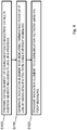
- Fig. 4 shows a flowchart illustrating a processing executed in a communication element like the UE 30 of Fig. 1 according to some examples of embodiments of the invention in a communication establishment mechanism as described above.
- step S100 the establishment of a communication connection to a cellular communication network via a multi-address bearer connection is prepared.
- the communication connection is provided with multiple addresses for IP based communication links, such as IPv6 links, wherein the addresses are IPv6 prefixes.
- an indication element for indicating at least one terminating point or breakout point i.e. a corresponding network element of the cellular communication network is generated.
- the terminating point based on one of the multiple addresses, data traffic is branched to another network e.g. the Internet or a local network by means of one of the IP based communication links.
- a specific PDU type code of a convergence protocol signaling such as a PDCP signaling is used.
- the specific PDU type code is allocated to a certain network element (e.g. eNB, SGW) being the terminating point.
- the generation of the indication element further comprises, according to some examples of embodiments of the invention, a mapping of the PDU type code element to a link layer address allocated to one of the IP based communication links.
- a common link layer addressing is applied for each network element involved in the communication connection via the multi-address bearer connection.
- the link layer address to which the PDU type code is mapped is mapped to a reserved EUI-64 identifier.
- the indication element for the generation of the indication element, information indicating a preferred terminating point for a data communication using the IP based communication links are received and considered.
- the information indicating the preferred terminating point is derived from a user input via a Ul providing selection options for entering an instruction indicating the preferred terminating point.
- the information is provided by the network, for example by using an IP based signaling, e.g. an IPv6 neighbor discovery protocol.
- step S120 the transmission of the indication element by means of a convergence protocol signaling, e.g. the PDCP signaling, to a communication network control element of the cellular communication network, like the eNB 10, is caused.
- a convergence protocol signaling e.g. the PDCP signaling
- Fig. 5 shows a flowchart illustrating a processing executed in a communication network control element like the eNB 10 of Fig. 1 according to examples of embodiments of the invention in a communication establishment mechanism as described above. It is to be noted that a similar processing is conducted, according to some examples of embodiments of the invention, also in a CN network element being usable as a terminating point, such as the SGW 20.
- step S200 procedures regarding a participation in an establishment of a communication connection in a cellular communication network via a multi-address bearer connection to a UE are executed.
- the communication connection is provided with multiple addresses for IP based communication links, such as IPv6 links, wherein the addresses are IPv6 prefixes.
- an indication element is received by means of a convergence protocol signaling, wherein the indication element indicates according to some examples of embodiments of the invention at least one terminating point in the form of a network element of the cellular communication network where data traffic, based on one of the multiple addresses, is branched or broken out to another network, such as the Internet, by means of one of the IP based communication links.
- the convergence protocol is PDCP, wherein the indication element is a PDU type code allocated to each possible network element (eNB, SGW) being the terminating point of the IP based communication links.
- the PDU type code is mapped to a link layer address allocated to one of the IP based communication links, or according to some other examples of embodiments of the invention a common conceptual link-layer addressing is used for each network element involved in the communication connection via the multi-address bearer connection. Furthermore, according to some examples of embodiments of the invention, the conceptual link-layer address, to which the PDU type code is mapped, is mapped to a reserved EUI-64 identifier.
- step S220 it is decided on the basis of the processing of the indication element whether the local network element (i.e. the network element in which the processing is conducted, such as the eNB or the SGW) is indicated as a terminating point.
- the local network element i.e. the network element in which the processing is conducted, such as the eNB or the SGW
- step S230 a communication via the breakout connection is started.
- a breakout connection to another network by an IP based communication link using the corresponding address (IPv6 prefix) is established.
- the eNB/SGW has established the breakout connection beforehand and indicated the availability of the breakout to the UE via a suitable signaling, e.g. via Router Advertisement.
- step S220 determines whether the decision in step S220 is negative or a multicast traffic is indicated. If the decision in step S220 is negative or a multicast traffic is indicated, the process proceeds to step S240 where forwarding of the indication element to a next network element (e.g. SGW or PGW) is caused.
- a next network element e.g. SGW or PGW
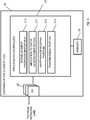
- a block circuit diagram illustrating a configuration of a communication element such as of UE 30, is shown, which is configured to implement the communication establishment mechanism as described in connection with the examples of embodiments of the invention.
- the communication element or UE 30 shown in Fig. 6 may comprise several further elements or functions besides those described herein below, which are omitted herein for the sake of simplicity as they are not essential for understanding the invention.
- the communication element may be also another device having a similar function, such as a chipset, a chip, a module etc., which can also be part of a UE or attached as a separate element to a UE, or the like.
- the communication element or UE 30 may comprise a processing function or processor 31, such as a CPU or the like, which executes instructions given by programs or the like related to the communication establishment mechanism.
- the processor 31 may comprise one or more processing portions dedicated to specific processing as described below, or the processing may be run in a single processor. Portions for executing such specific processing may be also provided as discrete elements or within one or more further processors or processing portions, such as in one physical processor like a CPU or in several physical entities, for example.
- Reference sign 32 denotes transceiver or input/output (I/O) units (interfaces) connected to the processor 31.
- the I/O units 32 may be used for communicating with one or more communication network control elements like the eNB 10, and with a communication network such as a WLAN, a IEEE 802.15.4 based network, a ZigBee network, Bluetooth, wired USB and Ethernet, and the like.
- the I/O units 32 may be a combined unit comprising communication equipment towards several network elements, or may comprise a distributed structure with a plurality of different interfaces for different network elements.
- Reference sign 33 denotes a memory usable, for example, for storing data and programs to be executed by the processor 31 and/or as a working storage of the processor 31.
- the processor 31 is configured to execute processing related to the above described communication establishment mechanism.
- the processor 31 comprises a sub-portion 310 as a processing portion which is usable for conducting a processing for preparing the establishment of a connection via a multi-address bearer.
- the portion 310 may be configured to perform a processing according to step S100 of Fig. 4 , for example.
- the processor 31 comprises a sub-portion 311 usable as a portion for generating an indication element related to the terminating point.
- the portion 311 may be configured to perform processing according to step S110 of Fig. 4 , for example.
- the processor 31 comprises a sub-portion 312 usable as a portion for conducting mapping and/or addressing.
- the portion 312 may be configured to perform processing related to the mapping described with regard to Fig. 2 , for example.
- the processor 31 comprises a sub-portion 313 as a processing portion which is usable for causing transmission of the indication element, e.g. via a PDCP signaling, to the network.
- the portion 313 may be configured to perform processing according to step S120 of Fig. 4 , for example.
- a block circuit diagram illustrating a configuration of a communication network control element, such as of eNB 10, is shown, which is configured to implement the communication establishment mechanism as described in connection with the examples of embodiments of the invention.
- the structure shown in Fig. 7 is basically also applicable for a core network control element, such as the SGW 20, which is able to conduct a similar processing with regard to the communication establishment procedure when receiving an indication as described above.
- the communication network control element or eNB 10 (or SGW 20) shown in Fig. 7 may comprise several further elements or functions besides those described herein below, which are omitted herein for the sake of simplicity as they are not essential for understanding the invention.
- the communication network control element may be also another device having a similar function, such as a chipset, a chip, a module etc., which can also be part of a control element or eNB or attached as a separate element to a control element like an eNB, or the like.
- the communication network control element or eNB 10 may comprise a processing function or processor 11, such as a CPU or the like, which executes instructions given by programs or the like related to the flow control mechanism.
- the processor 11 may comprise one or more processing portions dedicated to specific processing as described below, or the processing may be run in a single processor. Portions for executing such specific processing may be also provided as discrete elements or within one or more further processors or processing portions, such as in one physical processor like a CPU or in several physical entities, for example.
- Reference signs 12 and 13 denote transceiver or input/output (I/O) units (interfaces) connected to the processor 11.
- the I/O units 12 may be used for communicating towards a radio access for one or more communication elements like UEs, or to a corresponding network element like an eNB (in case of the SGW 20, for example).
- the I/O units 12 may be used for communicating with one or more core network control elements like the SGW 20 (in case of the eNB 10) or the PGW 40 (in case of the SGW 20).
- the I/O units 12 and 13 may be a combined unit comprising communication equipment towards several network elements, or may comprise a distributed structure with a plurality of different interfaces for different network elements.
- Reference sign 14 denotes a memory usable, for example, for storing data and programs to be executed by the processor 11 and/or as a working storage of the processor 11.
- the processor 11 is configured to execute processing related to the above described communication establishment mechanism.
- the processor 11 comprises a sub-portion 110 as a processing portion which is usable for conducting procedures related to a participation in the establishment of a communication connection via a multi-address bearer.
- the portion 110 may be configured to perform processing according to step S200 of Fig. 5 , for example.
- the processor 11 comprises a sub-portion 111 usable as a portion for receiving and processing an indication element indicating a terminating point.
- the portion 111 may be configured to perform processing according to step S210 of Fig. 5 , for example.
- the processor 11 comprises a sub-portion 112 usable as a portion for deciding whether or not the local network element is a terminating point.
- the portion 112 may be configured to perform processing according to step S230 of Fig. 5 , for example.
- the processor 11 comprises a sub-portion 113 as a processing portion which is usable for starting communication via a breakout connection (i.e. establishment of breakout connection or usage of established breakout connection).
- the portion 113 may be configured to perform processing according to step S240 of Fig. 5 , for example.
- the processor 11 comprises a sub-portion 114 usable as a portion for causing to forward the indication element to the next CN network element.
- the portion 114 may be configured to perform processing according to step S250 of Fig. 5 , for example.
- the eNB and the UE are configured to silently discards unknown PDCP PDU types, which makes the backward compatibility against the existing system even simpler to achieve.
- embodiments of the invention use the EUI-64 link-layer address in a mapping scheme so that so-called split-UE scenarios, such as USB dongles, MiFi (My-WiFi) equipment, or even for implementations where a handset is internally architectured as split-UE (separated mobile terminal and terminal equipment) are suitably supported.
- split-UE scenarios such as USB dongles, MiFi (My-WiFi) equipment, or even for implementations where a handset is internally architectured as split-UE (separated mobile terminal and terminal equipment) are suitably supported.
- an efficient traffic identification and separation is possible according to some examples of embodiments of the invention, since an identification/categorization of the connection to be established into one where a breakout connection is to be established at the eNB or one which concerns another network element can be done with minimal load using predefined PDCP PDU types (no IP lookup or IP inspection is required).
- the load for the remaining network elements can be kept small according to some examples of embodiments of the invention, since the breakout IP link is local to e.g. the eNB.
- the load for the system can be kept small according to some examples of embodiments of the invention, since the burden of PCC and other handover signaling can be avoided.
- an operator can decide which network element is to be preferred as a terminating point for a breakout connection.
- network operators can easily utilize mechanisms, such as one being based on IETF RFC4191, to choose which of network element, e.g. which of the three entities eNB, SGW, PGW is to be used as default gateway for an IP based link.
- the operator can configure the eNB 10 to be high priority default gateway, the SGW 20 to be mid-priority default gateway, and the PGW 40 to be low-priority default gateway.
- a Ul of the UE comprises a setting option for the user to select a preferred terminating point. That is, according to some examples of embodiments of the invention, for handsets usability reasons, a network management UI provides user control possibility for the breakouts. For example, the UI shows the user could a typical cellular connection selection menu or the like which, as one setting option (which can be the default setting option), maps to a connection to the PGW 40. In addition, there are provided sub-selection options for allowing/disallowing a breakout to occur at another terminating point, i.e.
- a IP based link from the PGW can be allowed/disallowed.
- the selection can be also provided by options like "Short range cellular data" (for eNB breakout), "Mid-range cellular data” (for SGW breakout), or the like.
- an apparatus comprising establishment preparation means for preparing the establishment of a communication connection to a cellular communication network via a multi-address bearer connection, the communication connection is provided with multiple addresses for Internet protocol based communication links, indication generation means for generating an indication element for indicating at least one terminating point represented by a network element of the cellular communication network where data traffic, based on at least one of the multiple addresses, is branched to another network being different to the cellular communication network by means of one of the Internet protocol based communication links, and transmission means for causing transmission of the indication element by means of a convergence protocol signaling to a communication network control element of the cellular communication network.
- an apparatus comprising processing means for conducting a processing for participating in an establishment of a communication connection in a cellular communication network via a multi-address bearer connection to a communication element, the communication connection is provided with multiple addresses for Internet protocol based communication links, indication receiving means for receiving, by means of a convergence protocol signaling, and processing an indication element for indicating at least one terminating point represented by a network element of the cellular communication network where data traffic, based on at least one of the multiple addresses, is branched to another network being different to the cellular communication network by means of one of the Internet protocol based communication links, and decision means for deciding on the basis of the processing of the indication element whether a local network element is indicated as a terminating point.
- a mechanism for establishing a single PDN connection with plural IP addresses and breakout or terminating points When a communication connection provided with multiple IP addresses via a multi-address bearer connection is established, an indication is prepared for indicating a terminating point represented by a network element of the cellular communication network where data traffic, based on one of the multiple IP addresses, is branched to another network being different to the cellular communication network by means of an IP based communication link.
- the indication element is sent to the communication network by means of a PDCP signaling e.g. as a new PDU type code.
- a local receiving network element is indicated as a terminating point, wherein in this case a breakout connection to another network being different to the cellular communication network by the IP based communication link is established.
Landscapes
- Engineering & Computer Science (AREA)
- Computer Networks & Wireless Communication (AREA)
- Signal Processing (AREA)
- Computer Security & Cryptography (AREA)
- Mobile Radio Communication Systems (AREA)
Claims (17)
- Procédé destiné à être utilisé dans un élément de communication communiquant dans un réseau de communication cellulaire, le procédé comprenant
la préparation (S100) de l'établissement d'une connexion de communication avec un réseau de communication cellulaire par le biais d'une seule connexion de supports à adresses multiples, la connexion de communication étant pourvue d'adresses multiples pour des liaisons de communication à protocole Internet,
la génération (S110) d'un élément d'indication destiné à indiquer au moins un point de terminaison représenté par un élément de réseau (10, 20) du réseau de communication cellulaire où un trafic de données, basé sur au moins une des adresses multiples, est aiguillé vers un autre réseau différent du réseau de communication cellulaire au moyen d'une des liaisons de communication à protocole Internet, et
la commande de la transmission (S120) de l'élément d'indication au moyen d'une signalisation à protocole de convergence à un élément de commande de réseau de communication (10) du réseau de communication cellulaire, le protocole de convergence consistant en un protocole de convergence de données en mode paquet utilisé entre un élément de communication (30) et l'élément de commande de réseau de communication (10), l'élément d'indication consistant en un élément de code de type d'unité de données en mode paquet, un élément de code de type d'unité de données en mode paquet spécifique étant alloué à chaque élément de réseau possible (10, 20) représentant un point de terminaison des liaisons de communication à protocole Internet du côté du réseau de communication cellulaire,
le procédé comprenant en outre
le mappage de l'élément de code de type d'unité de données en mode paquet sur une adresse de couche liaison allouée à l'une des liaisons de communication à protocole Internet, ou
l'utilisation d'un adressage commun en couche liaison pour chaque élément de réseau mis en jeu dans la connexion de communication par le biais de la seule connexion de supports à adresses multiples. - Procédé selon la revendication 1, dans lequel les liaisons de communication à protocole Internet consistent en des liaisons IPv6, et les adresses pour les liaisons de communication à protocole Internet consistent en des préfixes IPv6.
- Procédé selon la revendication 1 ou 2, comprenant en outre
le mappage de l'adresse de couche liaison, sur laquelle est mappé le code de type d'unité de données en mode paquet, sur un identifiant unique étendu réservé. - Procédé selon l'une quelconque des revendications 1 à 3, comprenant en outre
la réception d'informations indiquant un point de terminaison préféré pour une communication de données à l'aide des liaisons de communication à protocole Internet,
le point de terminaison préféré étant pris en compte dans la préparation de l'élément d'indication. - Procédé selon la revendication 4, comprenant en outre
la dérivation d'informations indiquant le point de terminaison préféré à partir d'une entrée utilisateur par le biais d'une interface utilisateur fournissant des options de sélection permettant la saisie d'une instruction indiquant le point de terminaison préféré, et/ou
la réception des informations indiquant le point de terminaison préféré depuis le réseau de communication cellulaire par le biais d'une signalisation à protocole Internet. - Procédé selon l'une quelconque des revendications 1 à 5, lequel procédé est mis en oeuvre dans un élément de communication (30) comprenant un dispositif terminal et/ou un équipement utilisateur se situant dans le réseau de communication cellulaire et communiquant avec un élément de commande de réseau de communication du réseau de communication cellulaire, l'élément de commande de réseau de communication (10) comprenant une station de base d'un réseau cellulaire et/ou un noeud B évolué d'un réseau de communication de type Évolution à Long Terme ou Évolution à Long Terme Avancée, et dans lequel l'élément de réseau (10, 20) représentant le point de terminaison comprend l'élément de commande de réseau de communication (10) et/ou un élément de commande de coeur de réseau (20) comportant un élément de réseau passerelle du réseau de communication cellulaire.
- Appareil (30), comprenant :au moins un processeur (31),au moins une interface (32) avec au moins un autre élément de réseau (10), etau moins une mémoire (33) destinée à stocker des instructions à exécuter par le processeur (31),l'au moins une mémoire (33) et les instructions étant configurées pour, conjointement avec l'au moins un processeur (31), amener l'appareil (30) au moins à réaliser :une fonction de préparation d'établissement (310) configurée pour préparer l'établissement d'une connexion de communication avec un réseau de communication cellulaire par le biais d'une seule connexion de supports à adresses multiples, la connexion de communication étant pourvue d'adresses multiples pour des liaisons de communication à protocole Internet,une fonction de génération d'indication (311) configurée pour générer un élément d'indication destiné à indiquer au moins un point de terminaison représenté par un élément de réseau (10, 20) du réseau de communication cellulaire où un trafic de données, basé sur au moins une des adresses multiples, est aiguillé vers un autre réseau différent du réseau de communication cellulaire au moyen d'une des liaisons de communication à protocole Internet, etune fonction de transmission (313) configurée pour commander la transmission de l'élément d'indication au moyen d'une signalisation à protocole de convergence à un élément de commande de réseau de communication (10) du réseau de communication cellulaire, le protocole de convergence consistant en une signalisation à protocole de convergence de données en mode paquet entre un élément de communication (30) et l'élément de commande de réseau de communication (10), et la fonction de génération d'indication étant configurée en outre pour générer l'élément d'indication sous la forme d'un élément de code de type d'unité de données en mode paquet, un élément de code de type d'unité de données en mode paquet spécifique étant alloué à chaque élément de réseau possible (10, 20) représentant un point de terminaison des liaisons de communication à protocole Internet du côté du réseau de communication cellulaire,l'au moins une mémoire (33) et les instructions étant configurées pour, conjointement avec l'au moins un processeur (31), amener l'appareil (30) au moins à réaliserune fonction de mappage (312) configurée pour mapper l'élément de code de type d'unité de données en mode paquet sur une adresse de couche liaison allouée à l'une des liaisons de communication à protocole Internet, ouune fonction d'adressage (312) configurée pour utiliser un adressage commun en couche liaison pour chaque élément de réseau mis en jeu dans la connexion de communication par le biais de la seule connexion de supports à adresses multiples.
- Procédé destiné à être utilisé dans un élément de commande de réseau de communication commandant une communication avec un élément de communication dans un réseau de communication cellulaire, le procédé comprenant
la mise en oeuvre (S200) d'un traitement destiné à établir une connexion de communication dans un réseau de communication cellulaire par le biais d'une seule connexion de supports à adresses multiples avec un élément de communication (30), la connexion de communication étant pourvue d'adresses multiples pour des liaisons de communication à protocole Internet,
la réception (S210), au moyen d'une signalisation à protocole de convergence, et le traitement d'un élément d'indication destiné à indiquer au moins un point de terminaison représenté par un élément de réseau (10, 20) du réseau de communication cellulaire où un trafic de données, basé sur au moins une des adresses multiples, est aiguillé vers un autre réseau différent du réseau de communication cellulaire au moyen d'une des liaisons de communication à protocole Internet, et
la détermination (S220), sur la base du traitement de l'élément d'indication, si un élément de réseau local est indiqué ou non comme point de terminaison,
le protocole de convergence consistant en un protocole de convergence de données en mode paquet utilisé entre un élément de communication (30) et un élément de commande de réseau de communication (10), l'élément d'indication consistant en un élément de code de type d'unité de données en mode paquet, un élément de code de type d'unité de données en mode paquet spécifique étant alloué à chaque élément de réseau possible (10, 20) représentant un point de terminaison des liaisons de communication à protocole Internet du côté du réseau de communication cellulaire, et
l'élément de code de type d'unité de données en mode paquet étant mappé sur une adresse de couche liaison allouée à l'une des liaisons de communication à protocole Internet, ou un adressage commun en couche liaison étant utilisé pour chaque élément de réseau mis en jeu dans la connexion de communication par le biais de la seule connexion de supports à adresses multiples. - Procédé selon la revendication 8, comprenant en outre
s'il est déterminé que l'élément de réseau local est indiqué comme point de terminaison, la commande (S230) de l'établissement d'une connexion de dégagement ou de l'utilisation d'une connexion de dégagement établie avec un autre réseau différent du réseau de communication cellulaire par une liaison de communication à protocole Internet à l'aide d'une des adresses multiples, et
s'il est déterminé que l'élément de réseau local n'est pas indiqué comme point de terminaison ou qu'un trafic multicast est indiqué, la commande (S240) du réacheminement de l'élément d'indication vers un élément de réseau du réseau de communication. - Procédé selon la revendication 8 ou 9, dans lequel les liaisons de communication à protocole Internet consistent en des liaisons IPv6, et les adresses pour les liaisons de communication à protocole Internet consistent en des préfixes IPv6.
- Procédé selon l'une quelconque des revendications 8 à 10, dans lequel l'adresse de couche liaison, sur laquelle est mappé le code de type d'unité de données en mode paquet, est mappée sur un identifiant unique étendu réservé.
- Procédé selon l'une quelconque des revendications 8 à 11, comprenant en outre
la commande de la transmission à l'élément de communication (30) d'informations indiquant un point de terminaison préféré pour une communication de données à l'aide des liaisons de communication à protocole Internet. - Procédé selon l'une quelconque des revendications 8 à 12, lequel procédé est mis en oeuvre dans un élément de commande de réseau de communication (10) comprenant une station de base d'un réseau cellulaire et/ou un noeud B évolué d'un réseau de communication de type Évolution à Long Terme ou Évolution à Long Terme Avancée et/ou un élément de commande de coeur de réseau (20) comportant un élément de réseau passerelle, l'élément de communication (30) comprenant un dispositif terminal et/ou un équipement utilisateur se situant dans le réseau de communication cellulaire et communiquant avec l'élément de commande de réseau de communication (10) du réseau de communication cellulaire.
- Appareil (10), comprenant
au moins un processeur (11),
au moins une interface (12, 13) avec au moins un autre élément de réseau, et
au moins une mémoire (14) destinée à stocker des instructions à exécuter par le processeur (11),
l'au moins une mémoire (14) et les instructions étant configurées pour, conjointement avec l'au moins un processeur (11), amener l'appareil (10) au moins à réaliser :une fonction de traitement (110) configurée pour mettre en oeuvre un traitement destiné à établir une connexion de communication dans un réseau de communication cellulaire par le biais d'une seule connexion de supports à adresses multiples avec un élément de communication (30), la connexion de communication étant pourvue d'adresses multiples pour des liaisons de communication à protocole Internet,une fonction de réception d'indication (111) configurée pour recevoir, au moyen d'une signalisation à protocole de convergence, et traiter un élément d'indication destiné à indiquer au moins un point de terminaison représenté par un élément de réseau du réseau de communication cellulaire où un trafic de données, basé sur au moins une des adresses multiples, est aiguillé vers un autre réseau différent du réseau de communication cellulaire au moyen d'une des liaisons de communication à protocole Internet, etune fonction de détermination (112) configurée pour déterminer, sur la base du traitement de l'élément d'indication, si un élément de réseau local est indiqué ou non comme point de terminaison, la fonction de réception d'indication (111) étant configurée en outre pour recevoir la signalisation à protocole de convergence sous forme d'une signalisation à protocole de convergence de données en mode paquet utilisée entre un élément de communication et un élément de commande de réseau de communication, l'élément d'indication consistant en un élément de code de type d'unité de données en mode paquet, un élément de code de type d'unité de données en mode paquet spécifique étant alloué à chaque élément de réseau possible représentant un point de terminaison des liaisons de communication à protocole Internet du côté du réseau de communication cellulaire,l'élément de code de type d'unité de données en mode paquet étant mappé sur une adresse de couche liaison allouée à l'une des liaisons de communication à protocole Internet, ou un adressage commun en couche liaison étant utilisé pour chaque élément de réseau mis en jeu dans la connexion de communication par le biais de la seule connexion de supports à adresses multiples. - Produit-programme d'ordinateur pour un ordinateur, comprenant des parties de code logiciel dont l'exécution par l'ordinateur amène l'ordinateur à réaliser chacune des étapes de procédé de l'une quelconque des revendications 1 à 6.
- Produit-programme d'ordinateur pour un ordinateur, comprenant des parties de code logiciel dont l'exécution par l'ordinateur amène l'ordinateur à réaliser chacune des étapes de procédé de l'une quelconque des revendications 8 à 13.
- Produit-programme d'ordinateur selon la revendication 15 ou la revendication 16,
lequel produit-programme d'ordinateur comprend un support lisible par ordinateur sur lequel sont enregistrées lesdites parties de code logiciel, et/ou
lequel produit-programme d'ordinateur est chargeable directement dans la mémoire interne de l'ordinateur et/ou transmissible par le biais d'un réseau au moyen d'au moins une procédure parmi une procédure de téléchargement en amont, une procédure de téléchargement en aval et une procédure de pousser.
Applications Claiming Priority (1)
| Application Number | Priority Date | Filing Date | Title |
|---|---|---|---|
| PCT/EP2012/069255 WO2014048499A1 (fr) | 2012-09-28 | 2012-09-28 | Mécanisme permettant d'établir une connexion de réseau de données à commutation par paquets avec de multiples adresses ip |
Publications (2)
| Publication Number | Publication Date |
|---|---|
| EP2901732A1 EP2901732A1 (fr) | 2015-08-05 |
| EP2901732B1 true EP2901732B1 (fr) | 2019-06-19 |
Family
ID=46982580
Family Applications (1)
| Application Number | Title | Priority Date | Filing Date |
|---|---|---|---|
| EP12769397.6A Not-in-force EP2901732B1 (fr) | 2012-09-28 | 2012-09-28 | Mécanisme permettant d'établir une connexion de réseau de données à commutation par paquets avec de multiples adresses ip |
Country Status (3)
| Country | Link |
|---|---|
| US (1) | US10159100B2 (fr) |
| EP (1) | EP2901732B1 (fr) |
| WO (1) | WO2014048499A1 (fr) |
Families Citing this family (12)
| Publication number | Priority date | Publication date | Assignee | Title |
|---|---|---|---|---|
| WO2014113190A1 (fr) * | 2013-01-17 | 2014-07-24 | Intel IP Corporation | Procédé, appareil et système de gestion de supports dans un système de communications sans fil |
| US10028215B2 (en) * | 2013-01-18 | 2018-07-17 | Lg Electronics Inc. | Method and terminal for selecting AP |
| CN103945461A (zh) * | 2013-01-23 | 2014-07-23 | 中兴通讯股份有限公司 | 数据多流传输方法及装置 |
| CN105634979B (zh) * | 2014-10-31 | 2019-01-01 | 中国移动通信集团公司 | 一种热点流量信息的处理方法、装置、终端以及MiFi |
| EP3316526A4 (fr) * | 2015-07-30 | 2018-07-25 | Huawei Technologies Co., Ltd. | Procédé, appareil et dispositif de transmission de données et de génération de table de mise en correspondance d'adresses |
| EP3459228A1 (fr) * | 2016-05-18 | 2019-03-27 | Telefonaktiebolaget LM Ericsson (PUBL) | Dérivation locale dans des réseaux ip mobiles |
| CN110235510B (zh) | 2017-02-01 | 2021-01-15 | 华为技术有限公司 | NextGen移动核心网中增强会话管理的系统和方法 |
| EP3963829A1 (fr) | 2019-05-02 | 2022-03-09 | Nokia Technologies Oy | Intégration de réseau de communication dans un système de mise en réseau sensible au temps |
| CN113647073A (zh) * | 2019-07-25 | 2021-11-12 | Oppo广东移动通信有限公司 | 用于传输数据的方法、发送端设备和接收端设备 |
| CN112738113B (zh) * | 2020-12-31 | 2022-04-01 | 清华大学 | 一种组织信息标签生成方法及报文传输方法 |
| US11758428B2 (en) * | 2021-05-07 | 2023-09-12 | Microsoft Technology Licensing, Llc | Techniques for providing traffic flow template (TFT) information in wireless communications |
| US12587405B2 (en) * | 2022-10-12 | 2026-03-24 | Juniper Networks, Inc. | Multicast local breakout for customer premise equipment in a 5G wireless wireline convergence at an access gateway function |
Family Cites Families (8)
| Publication number | Priority date | Publication date | Assignee | Title |
|---|---|---|---|---|
| US6587462B2 (en) * | 2001-02-16 | 2003-07-01 | Dunti Corporation | Address mapping mechanism enabling multi-domain addressing in communication networks |
| US20040148428A1 (en) * | 2003-01-28 | 2004-07-29 | George Tsirtsis | Methods and apparatus for supporting an internet protocol (IP) version independent mobility management system |
| WO2008142620A2 (fr) | 2007-05-18 | 2008-11-27 | Nokia Corporation | Système et procédé pour fournir des services de démarrage ip local employant des noms de point d'accès |
| RU2518186C2 (ru) | 2008-10-01 | 2014-06-10 | Телефонактиеболагет Лм Эрикссон (Пабл) | Обработка трафика локального непосредственного соединенения в домашней базовой станции |
| US20110110378A1 (en) * | 2009-11-10 | 2011-05-12 | Nokia Corporation | Method and Apparatus for Communications Traffic Breakout |
| US9021072B2 (en) * | 2010-01-28 | 2015-04-28 | Verizon Patent And Licensing Inc. | Localized media offload |
| US8520615B2 (en) * | 2010-03-26 | 2013-08-27 | Juniper Networks, Inc. | Breakout gateway for mobile data traffic |
| US9839056B2 (en) * | 2011-12-07 | 2017-12-05 | Nokia Solutions And Networks Oy | Link model for multi-prefix packet system bearer |
-
2012
- 2012-09-28 US US14/431,979 patent/US10159100B2/en not_active Expired - Fee Related
- 2012-09-28 EP EP12769397.6A patent/EP2901732B1/fr not_active Not-in-force
- 2012-09-28 WO PCT/EP2012/069255 patent/WO2014048499A1/fr not_active Ceased
Non-Patent Citations (1)
| Title |
|---|
| None * |
Also Published As
| Publication number | Publication date |
|---|---|
| US10159100B2 (en) | 2018-12-18 |
| WO2014048499A1 (fr) | 2014-04-03 |
| EP2901732A1 (fr) | 2015-08-05 |
| US20150215971A1 (en) | 2015-07-30 |
Similar Documents
| Publication | Publication Date | Title |
|---|---|---|
| EP2901732B1 (fr) | Mécanisme permettant d'établir une connexion de réseau de données à commutation par paquets avec de multiples adresses ip | |
| CN105637905B (zh) | 用于实现pdn连接的方法、装置和系统 | |
| CN106664732B (zh) | 用于具有lte连接的多径tcp的装置和方法 | |
| EP4030864B1 (fr) | Liaison de plusieurs sessions | |
| CN102349350B (zh) | 具有优化接口的本地疏导 | |
| JP6105758B2 (ja) | 無線通信システムにおけるセルラセッションを設定する方法及び装置 | |
| EP2676463B1 (fr) | Routeur mobile et méthode dans un eps | |
| CN107852664B (zh) | 移动热点 | |
| CN104255058B (zh) | 单一无线电切换的系统和方法 | |
| CN102984782B (zh) | 一种多模智能接入方法、设备和系统 | |
| CN108886729A (zh) | 与传统无线接入技术交互工作用于连接到下一代核心网 | |
| GB2494460A (en) | Registering and attaching to a communication network for device-to-device (D2D) communication | |
| CN113194511A (zh) | 用于系统间移动性的服务网关扩展 | |
| AU2019274046B2 (en) | User equipment, control apparatus, and communication control method | |
| CN113950106A (zh) | 多接入连接建立的方法、装置和系统 | |
| WO2017016615A1 (fr) | Point d'accès sans fil mobile | |
| WO2015062643A1 (fr) | Maintenir un équipement d'utilisateur dans un état rattaché à un réseau de communication cellulaire durant le délestage de données cellulaires à un autre réseau de communication | |
| CN107431875A (zh) | 终端装置、分组数据网络网关及移动性管理实体 | |
| WO2025209303A1 (fr) | Procédé de communication et appareil de communication | |
| WO2019214105A1 (fr) | Procédé et appareil de liaison de flux de données et support de stockage informatique | |
| HK1235598A1 (en) | Multipath tcp with lte connections | |
| HK1235598B (zh) | 用於具有lte连接的多径tcp的装置和方法 |
Legal Events
| Date | Code | Title | Description |
|---|---|---|---|
| PUAI | Public reference made under article 153(3) epc to a published international application that has entered the european phase |
Free format text: ORIGINAL CODE: 0009012 |
|
| 17P | Request for examination filed |
Effective date: 20150428 |
|
| AK | Designated contracting states |
Kind code of ref document: A1 Designated state(s): AL AT BE BG CH CY CZ DE DK EE ES FI FR GB GR HR HU IE IS IT LI LT LU LV MC MK MT NL NO PL PT RO RS SE SI SK SM TR |
|
| AX | Request for extension of the european patent |
Extension state: BA ME |
|
| DAX | Request for extension of the european patent (deleted) | ||
| STAA | Information on the status of an ep patent application or granted ep patent |
Free format text: STATUS: EXAMINATION IS IN PROGRESS |
|
| 17Q | First examination report despatched |
Effective date: 20180221 |
|
| REG | Reference to a national code |
Ref country code: DE Ref legal event code: R079 Ref document number: 602012061187 Country of ref document: DE Free format text: PREVIOUS MAIN CLASS: H04W0008260000 Ipc: H04W0076120000 |
|
| RIC1 | Information provided on ipc code assigned before grant |
Ipc: H04W 76/12 20180101AFI20181113BHEP Ipc: H04L 29/12 20060101ALN20181113BHEP Ipc: H04W 76/11 20180101ALN20181113BHEP |
|
| RIC1 | Information provided on ipc code assigned before grant |
Ipc: H04W 76/12 20180101AFI20181123BHEP Ipc: H04W 76/11 20180101ALN20181123BHEP Ipc: H04L 29/12 20060101ALN20181123BHEP |
|
| RIC1 | Information provided on ipc code assigned before grant |
Ipc: H04L 29/12 20060101ALN20181203BHEP Ipc: H04W 76/11 20180101ALN20181203BHEP Ipc: H04W 76/12 20180101AFI20181203BHEP |
|
| GRAP | Despatch of communication of intention to grant a patent |
Free format text: ORIGINAL CODE: EPIDOSNIGR1 |
|
| STAA | Information on the status of an ep patent application or granted ep patent |
Free format text: STATUS: GRANT OF PATENT IS INTENDED |
|
| INTG | Intention to grant announced |
Effective date: 20190111 |
|
| RIC1 | Information provided on ipc code assigned before grant |
Ipc: H04W 76/11 20180101ALN20181203BHEP Ipc: H04L 29/12 20060101ALN20181203BHEP Ipc: H04W 76/12 20180101AFI20181203BHEP |
|
| GRAS | Grant fee paid |
Free format text: ORIGINAL CODE: EPIDOSNIGR3 |
|
| GRAA | (expected) grant |
Free format text: ORIGINAL CODE: 0009210 |
|
| STAA | Information on the status of an ep patent application or granted ep patent |
Free format text: STATUS: THE PATENT HAS BEEN GRANTED |
|
| AK | Designated contracting states |
Kind code of ref document: B1 Designated state(s): AL AT BE BG CH CY CZ DE DK EE ES FI FR GB GR HR HU IE IS IT LI LT LU LV MC MK MT NL NO PL PT RO RS SE SI SK SM TR |
|
| REG | Reference to a national code |
Ref country code: GB Ref legal event code: FG4D |
|
| REG | Reference to a national code |
Ref country code: CH Ref legal event code: EP |
|
| REG | Reference to a national code |
Ref country code: IE Ref legal event code: FG4D |
|
| REG | Reference to a national code |
Ref country code: AT Ref legal event code: REF Ref document number: 1147160 Country of ref document: AT Kind code of ref document: T Effective date: 20190715 |
|
| REG | Reference to a national code |
Ref country code: DE Ref legal event code: R096 Ref document number: 602012061187 Country of ref document: DE |
|
| RAP2 | Party data changed (patent owner data changed or rights of a patent transferred) |
Owner name: NOKIA SOLUTIONS AND NETWORKS OY |
|
| REG | Reference to a national code |
Ref country code: NL Ref legal event code: MP Effective date: 20190619 |
|
| PG25 | Lapsed in a contracting state [announced via postgrant information from national office to epo] |
Ref country code: FI Free format text: LAPSE BECAUSE OF FAILURE TO SUBMIT A TRANSLATION OF THE DESCRIPTION OR TO PAY THE FEE WITHIN THE PRESCRIBED TIME-LIMIT Effective date: 20190619 Ref country code: LT Free format text: LAPSE BECAUSE OF FAILURE TO SUBMIT A TRANSLATION OF THE DESCRIPTION OR TO PAY THE FEE WITHIN THE PRESCRIBED TIME-LIMIT Effective date: 20190619 Ref country code: AL Free format text: LAPSE BECAUSE OF FAILURE TO SUBMIT A TRANSLATION OF THE DESCRIPTION OR TO PAY THE FEE WITHIN THE PRESCRIBED TIME-LIMIT Effective date: 20190619 Ref country code: HR Free format text: LAPSE BECAUSE OF FAILURE TO SUBMIT A TRANSLATION OF THE DESCRIPTION OR TO PAY THE FEE WITHIN THE PRESCRIBED TIME-LIMIT Effective date: 20190619 Ref country code: NO Free format text: LAPSE BECAUSE OF FAILURE TO SUBMIT A TRANSLATION OF THE DESCRIPTION OR TO PAY THE FEE WITHIN THE PRESCRIBED TIME-LIMIT Effective date: 20190919 Ref country code: SE Free format text: LAPSE BECAUSE OF FAILURE TO SUBMIT A TRANSLATION OF THE DESCRIPTION OR TO PAY THE FEE WITHIN THE PRESCRIBED TIME-LIMIT Effective date: 20190619 |
|
| REG | Reference to a national code |
Ref country code: LT Ref legal event code: MG4D |
|
| PG25 | Lapsed in a contracting state [announced via postgrant information from national office to epo] |
Ref country code: RS Free format text: LAPSE BECAUSE OF FAILURE TO SUBMIT A TRANSLATION OF THE DESCRIPTION OR TO PAY THE FEE WITHIN THE PRESCRIBED TIME-LIMIT Effective date: 20190619 Ref country code: LV Free format text: LAPSE BECAUSE OF FAILURE TO SUBMIT A TRANSLATION OF THE DESCRIPTION OR TO PAY THE FEE WITHIN THE PRESCRIBED TIME-LIMIT Effective date: 20190619 Ref country code: GR Free format text: LAPSE BECAUSE OF FAILURE TO SUBMIT A TRANSLATION OF THE DESCRIPTION OR TO PAY THE FEE WITHIN THE PRESCRIBED TIME-LIMIT Effective date: 20190920 Ref country code: BG Free format text: LAPSE BECAUSE OF FAILURE TO SUBMIT A TRANSLATION OF THE DESCRIPTION OR TO PAY THE FEE WITHIN THE PRESCRIBED TIME-LIMIT Effective date: 20190919 |
|
| REG | Reference to a national code |
Ref country code: AT Ref legal event code: MK05 Ref document number: 1147160 Country of ref document: AT Kind code of ref document: T Effective date: 20190619 |
|
| PG25 | Lapsed in a contracting state [announced via postgrant information from national office to epo] |
Ref country code: SK Free format text: LAPSE BECAUSE OF FAILURE TO SUBMIT A TRANSLATION OF THE DESCRIPTION OR TO PAY THE FEE WITHIN THE PRESCRIBED TIME-LIMIT Effective date: 20190619 Ref country code: RO Free format text: LAPSE BECAUSE OF FAILURE TO SUBMIT A TRANSLATION OF THE DESCRIPTION OR TO PAY THE FEE WITHIN THE PRESCRIBED TIME-LIMIT Effective date: 20190619 Ref country code: CZ Free format text: LAPSE BECAUSE OF FAILURE TO SUBMIT A TRANSLATION OF THE DESCRIPTION OR TO PAY THE FEE WITHIN THE PRESCRIBED TIME-LIMIT Effective date: 20190619 Ref country code: NL Free format text: LAPSE BECAUSE OF FAILURE TO SUBMIT A TRANSLATION OF THE DESCRIPTION OR TO PAY THE FEE WITHIN THE PRESCRIBED TIME-LIMIT Effective date: 20190619 Ref country code: AT Free format text: LAPSE BECAUSE OF FAILURE TO SUBMIT A TRANSLATION OF THE DESCRIPTION OR TO PAY THE FEE WITHIN THE PRESCRIBED TIME-LIMIT Effective date: 20190619 Ref country code: EE Free format text: LAPSE BECAUSE OF FAILURE TO SUBMIT A TRANSLATION OF THE DESCRIPTION OR TO PAY THE FEE WITHIN THE PRESCRIBED TIME-LIMIT Effective date: 20190619 Ref country code: PT Free format text: LAPSE BECAUSE OF FAILURE TO SUBMIT A TRANSLATION OF THE DESCRIPTION OR TO PAY THE FEE WITHIN THE PRESCRIBED TIME-LIMIT Effective date: 20191021 |
|
| PG25 | Lapsed in a contracting state [announced via postgrant information from national office to epo] |
Ref country code: IT Free format text: LAPSE BECAUSE OF FAILURE TO SUBMIT A TRANSLATION OF THE DESCRIPTION OR TO PAY THE FEE WITHIN THE PRESCRIBED TIME-LIMIT Effective date: 20190619 Ref country code: SM Free format text: LAPSE BECAUSE OF FAILURE TO SUBMIT A TRANSLATION OF THE DESCRIPTION OR TO PAY THE FEE WITHIN THE PRESCRIBED TIME-LIMIT Effective date: 20190619 Ref country code: IS Free format text: LAPSE BECAUSE OF FAILURE TO SUBMIT A TRANSLATION OF THE DESCRIPTION OR TO PAY THE FEE WITHIN THE PRESCRIBED TIME-LIMIT Effective date: 20191019 Ref country code: ES Free format text: LAPSE BECAUSE OF FAILURE TO SUBMIT A TRANSLATION OF THE DESCRIPTION OR TO PAY THE FEE WITHIN THE PRESCRIBED TIME-LIMIT Effective date: 20190619 |
|
| PG25 | Lapsed in a contracting state [announced via postgrant information from national office to epo] |
Ref country code: TR Free format text: LAPSE BECAUSE OF FAILURE TO SUBMIT A TRANSLATION OF THE DESCRIPTION OR TO PAY THE FEE WITHIN THE PRESCRIBED TIME-LIMIT Effective date: 20190619 |
|
| REG | Reference to a national code |
Ref country code: DE Ref legal event code: R119 Ref document number: 602012061187 Country of ref document: DE |
|
| PG25 | Lapsed in a contracting state [announced via postgrant information from national office to epo] |
Ref country code: PL Free format text: LAPSE BECAUSE OF FAILURE TO SUBMIT A TRANSLATION OF THE DESCRIPTION OR TO PAY THE FEE WITHIN THE PRESCRIBED TIME-LIMIT Effective date: 20190619 Ref country code: DK Free format text: LAPSE BECAUSE OF FAILURE TO SUBMIT A TRANSLATION OF THE DESCRIPTION OR TO PAY THE FEE WITHIN THE PRESCRIBED TIME-LIMIT Effective date: 20190619 |
|
| PG25 | Lapsed in a contracting state [announced via postgrant information from national office to epo] |
Ref country code: IS Free format text: LAPSE BECAUSE OF FAILURE TO SUBMIT A TRANSLATION OF THE DESCRIPTION OR TO PAY THE FEE WITHIN THE PRESCRIBED TIME-LIMIT Effective date: 20200224 Ref country code: MC Free format text: LAPSE BECAUSE OF FAILURE TO SUBMIT A TRANSLATION OF THE DESCRIPTION OR TO PAY THE FEE WITHIN THE PRESCRIBED TIME-LIMIT Effective date: 20190619 |
|
| REG | Reference to a national code |
Ref country code: CH Ref legal event code: PL |
|
| PLBE | No opposition filed within time limit |
Free format text: ORIGINAL CODE: 0009261 |
|
| STAA | Information on the status of an ep patent application or granted ep patent |
Free format text: STATUS: NO OPPOSITION FILED WITHIN TIME LIMIT |
|
| PG2D | Information on lapse in contracting state deleted |
Ref country code: IS |
|
| PG25 | Lapsed in a contracting state [announced via postgrant information from national office to epo] |
Ref country code: IE Free format text: LAPSE BECAUSE OF NON-PAYMENT OF DUE FEES Effective date: 20190928 Ref country code: CH Free format text: LAPSE BECAUSE OF NON-PAYMENT OF DUE FEES Effective date: 20190930 Ref country code: LI Free format text: LAPSE BECAUSE OF NON-PAYMENT OF DUE FEES Effective date: 20190930 Ref country code: LU Free format text: LAPSE BECAUSE OF NON-PAYMENT OF DUE FEES Effective date: 20190928 Ref country code: DE Free format text: LAPSE BECAUSE OF NON-PAYMENT OF DUE FEES Effective date: 20200401 |
|
| REG | Reference to a national code |
Ref country code: BE Ref legal event code: MM Effective date: 20190930 |
|
| 26N | No opposition filed |
Effective date: 20200603 |
|
| PG25 | Lapsed in a contracting state [announced via postgrant information from national office to epo] |
Ref country code: SI Free format text: LAPSE BECAUSE OF FAILURE TO SUBMIT A TRANSLATION OF THE DESCRIPTION OR TO PAY THE FEE WITHIN THE PRESCRIBED TIME-LIMIT Effective date: 20190619 Ref country code: BE Free format text: LAPSE BECAUSE OF NON-PAYMENT OF DUE FEES Effective date: 20190930 |
|
| GBPC | Gb: european patent ceased through non-payment of renewal fee |
Effective date: 20190928 |
|
| PG25 | Lapsed in a contracting state [announced via postgrant information from national office to epo] |
Ref country code: GB Free format text: LAPSE BECAUSE OF NON-PAYMENT OF DUE FEES Effective date: 20190928 Ref country code: FR Free format text: LAPSE BECAUSE OF NON-PAYMENT OF DUE FEES Effective date: 20190930 |
|
| PG25 | Lapsed in a contracting state [announced via postgrant information from national office to epo] |
Ref country code: CY Free format text: LAPSE BECAUSE OF FAILURE TO SUBMIT A TRANSLATION OF THE DESCRIPTION OR TO PAY THE FEE WITHIN THE PRESCRIBED TIME-LIMIT Effective date: 20190619 |
|
| PG25 | Lapsed in a contracting state [announced via postgrant information from national office to epo] |
Ref country code: MT Free format text: LAPSE BECAUSE OF FAILURE TO SUBMIT A TRANSLATION OF THE DESCRIPTION OR TO PAY THE FEE WITHIN THE PRESCRIBED TIME-LIMIT Effective date: 20190619 Ref country code: HU Free format text: LAPSE BECAUSE OF FAILURE TO SUBMIT A TRANSLATION OF THE DESCRIPTION OR TO PAY THE FEE WITHIN THE PRESCRIBED TIME-LIMIT; INVALID AB INITIO Effective date: 20120928 |
|
| PG25 | Lapsed in a contracting state [announced via postgrant information from national office to epo] |
Ref country code: MK Free format text: LAPSE BECAUSE OF FAILURE TO SUBMIT A TRANSLATION OF THE DESCRIPTION OR TO PAY THE FEE WITHIN THE PRESCRIBED TIME-LIMIT Effective date: 20190619 |