EP2901854A1 - Corps creux - Google Patents
Corps creux Download PDFInfo
- Publication number
- EP2901854A1 EP2901854A1 EP15000184.0A EP15000184A EP2901854A1 EP 2901854 A1 EP2901854 A1 EP 2901854A1 EP 15000184 A EP15000184 A EP 15000184A EP 2901854 A1 EP2901854 A1 EP 2901854A1
- Authority
- EP
- European Patent Office
- Prior art keywords
- outer shell
- plug
- opening
- hollow body
- cavity
- Prior art date
- Legal status (The legal status is an assumption and is not a legal conclusion. Google has not performed a legal analysis and makes no representation as to the accuracy of the status listed.)
- Granted
Links
Images


Classifications
-
- A—HUMAN NECESSITIES
- A01—AGRICULTURE; FORESTRY; ANIMAL HUSBANDRY; HUNTING; TRAPPING; FISHING
- A01K—ANIMAL HUSBANDRY; AVICULTURE; APICULTURE; PISCICULTURE; FISHING; REARING OR BREEDING ANIMALS, NOT OTHERWISE PROVIDED FOR; NEW BREEDS OF ANIMALS
- A01K15/00—Devices for taming animals, e.g. nose-rings or hobbles; Devices for overturning animals in general; Training or exercising equipment; Covering boxes
- A01K15/02—Training or exercising equipment, e.g. mazes or labyrinths for animals ; Electric shock devices; Toys specially adapted for animals
- A01K15/025—Toys specially adapted for animals
Definitions
- the present invention relates to a hollow body, in particular suitable for biting into the dog, having at least one outer shell and at least one outer shell surrounded by the cavity and at least one opening in the outer shell from the outside into the cavity, wherein the opening is closed and in Cavity at least one magnetic or magnetizable body is arranged.
- Hollow body of this type which are particularly suitable for multiple biting into a dog, are in the prior art, for example from the EP 2 255 617 B1 known. They can be used in dog training or for dog training, for example, for the confirmation of a dog, if he has successfully mastered an exercise. Like in the EP 2 255 617 B1 already stated, it is important for avoiding injuries, especially tooth loss, in the dog that it is avoided that the dog's teeth can penetrate into the openings in the outer shell of the hollow body. After the magnet has been inserted into the cavity of the outer sheath, the opening must be closed to a firm fit in order to avoid the aforementioned injuries or tooth losses in the dog.
- the opening is closed with a plug, which is fastened both in the direction of the cavity and in the direction out of the cavity at the edge surrounding the opening of the outer shell is.
- the use according to the invention of the plug for closing the opening is, on the one hand, a relatively inexpensive and easy to assemble solution. On the other hand, it can also be reliably prevented with the plug that the dog loses a tooth when it bites into the hollow body, the tooth breaks off or the dog is otherwise injured.
- the plug is according to the invention arranged in the opening and attached to the edge surrounding the opening of the outer shell, that he bite the dog on the hollow body neither in the direction of the cavity nor in the direction out of the cavity out of its closed position for closing the opening can be moved out.
- This attachment which acts in both of these directions, is realized in contrast to the above-mentioned prior art to the surrounding a single opening edge of the outer shell.
- the rope used there for the closure is attached to the two edges, the opposite openings and must for this purpose through the cavity passed through the hollow body and then knotted tightly on both opposite sides accordingly.
- the plug which closes the opening is fixed positively and / or cohesively on the edge of the outer shell surrounding the opening.
- the plug is fastened exclusively to the edge of the outer casing surrounding the opening.
- the stopper is fixed immovably to the edge of the outer shell surrounding the opening.
- the stopper has two connected and spaced-apart collars and the edge of the outer shell surrounding the opening is held in a form-fitting manner between the collars.
- the surrounding the opening edge of the outer shell and / or at least one of the collars of the plug should be favorably designed so elastic that at least one of the collars of the plug can be passed through the opening, in which passing the edge of the outer shell and / or the collar or the plug can be elastically deformed accordingly.
- An alternative of the positive fastening of the plug in the opening provides that the plug and / or the edge of the outer shell surrounding the opening has or have at least one thread and the plug and the outer shell are fastened by means of the thread form-fitting together. It may be provided both on the plug and on the edge surrounding the opening of the outer shell a thread. But it can also be provided in advance only a thread, so that only when screwing the plug the Corresponding thread for this purpose in the corresponding part, so the plug or the surrounding the opening edge of the outer shell is cut.
- a preferred embodiment of a material-locking attachment of the plug on the edge of the outer shell surrounding the opening provides that the stopper closing the opening is adhesively bonded or vulcanized onto the edge of the outer shell surrounding the opening or fused into it.
- the plug is a plastic part.
- a plastic part may completely or only partially made of plastic. If it is only partially made of plastic, so the plastic is conveniently formed a jacket forming the outer surface of the plug. It may be a monomaterial but also a composition of different materials, in particular plastics, for example, in order to realize different elasticities in different areas of the plug.
- the plug is particularly preferably a plastic injection-molded part, that is to say an injection-molded plug made of plastic.
- Preferred plastics from which the plug consist or which it may have are, for example, polyvinyl chloride (PVC), polypropylene (PP), polyethylene (PE), Polyamide (PA), rubber, ethylene-propylene-diene rubber (EPDM) or thermoplastic polyurethane (TPU).
- PVC polyvinyl chloride
- PP polypropylene
- PE polyethylene
- PA Polyamide
- EPDM ethylene-propylene-diene rubber
- TPU thermoplastic polyurethane
- the outer shell of the hollow body should on the one hand be so flexible that it allows a certain deformation when biting in by the dog to avoid tooth injury in the dog. On the other hand, it must also be so stable that it can withstand the already mentioned very high pressures when biting the dog permanently.
- the outer shell is a plastic sleeve or a rubber sleeve or consists of a mixture thereof.
- PVC or polyurethane (PU) is used for a plastic sleeve.
- PU polyurethane
- the wall thickness of the outer shell should be apart from the opening conveniently in the range between 2mm and 1cm, more preferably in the range between 3mm and 7mm. In the sense of a sufficient stability of the outer shell when biting through the dog, it is also advantageous if the outer shell is designed seamless. In preferred embodiments, the plug is harder than the outer shell. But this can also be done the other way round. Of course, it is also conceivable to produce plugs and outer shells from the same or at least the same hard material.
- the hollow body can have a wide variety of outer shapes. Referring to its preferred field of use as a body for biting a dog, it may also be referred to as a bite. Particularly preferred embodiments provide that the hollow body is a ball. To incorrect polarity in the magnetic fastening of the hollow body to a support body as in EP 2 255 617 B1 or directly to a magnetic or magnetizable part of a garment is conveniently provided that the magnetic or magnetizable body is freely movable in the cavity.
- the closure of the opening by means of plug relative to that in the EP 2 255 617 B1 closure variant shown a further improvement, since according to the invention arranged on a in the cavity of the outer shell Piece of rope can be dispensed with and thus the magnetic or magnetizable body is particularly easy to move freely in the cavity.
- the magnetic or magnetizable body within the cavity can in each case align itself freely in order to prevent accidental repulsion with a magnet in a carrier body or in the clothes of the dog trainer due to incorrect polarity.
- This also makes it possible to attach the bite body, preferably in any position, to the carrier body.
- An alternative embodiment of the invention provides that the magnetic or magnetizable body is fixed to the stopper, preferably on an extension of the stopper extending into the cavity.
- the magnetic or magnetizable body is located in the middle of the cavity.
- it is particularly preferred that it is a magnetizable body, which can be attracted regardless of the polarity of an external magnet.
- hollow body according to the invention can be performed completely without a handle element.
- a fastening device for attaching an outside of the outer shell can be arranged, preferably flexible, handle member is arranged.
- the grip element can be designed as a rigid rod, but also flexible, for example in the form of a string, a rope or a band.
- the grip element may have, for example, a length between 10 and 40 cm outside the hollow body.
- the grip element can serve to make the hollow body together with the grip element appear to the dog during the movement of the dog trainer as a living object.
- the grip element can also be provided to perform Zerr réelle and the like with the dog.
- Simple fastening devices of the plug can, for. B. arranged outside the hollow body eyelets can be passed through the strings, ropes or bands. It may also be provided as a fastening device passing through the plug hole in which a Cord, a rope or a band is fastened accordingly. Also blind holes in the plug are conceivable as a fastening device. It may also be threaded, locking shoulders for locking heads or locking heads per se and the like. These can also be designed as nondestructive releasable fastening devices for the handle element on the stopper. Here are in turn screw and clamp connections, snap closures, carabiner-like closable hooks and the like as examples.
- Hollow body according to the invention can by means of their magnetic or magnetizable body, as in the EP 2 255 617 B1 shown to be attached via the aid of one or two-piece bodies to the clothes of a dog trainer.
- magnets or corresponding magnetizable material can be sewn into the clothing, be arranged in local pockets or the like.
- a magnet is enough in the entire arrangement. This can be arranged as a magnetic body in the cavity, but also part of the carrier body or in the clothes of the dog trainer.
- a first embodiment of a hollow body 1 according to the invention is shown.
- the hollow body 1 is a ball.
- the hollow body 1 can also have completely different shapes and in particular outer contours.
- the embodiment according to Fig. 1 has the outer shell 2 surrounding the cavity 2 of the hollow body 1, two opposing openings 4. These connect the cavity 3 in each case with the area outside the hollow body 1, as long as they are not closed with a respective stopper 6.
- the magnetizable or magnetic body 5 can be introduced into the cavity 3 before the introduction of the plug 6. This allows, for example, the outer shell 2 of the hollow body 1 form seamless.
- the body 5 is made of magnetic material, for example, permanent magnets known in the art may be used as the body 5.
- bodies 5 of magnetizable material all known in the prior art, usable here magnetizable materials, in particular metals, in question.
- the plug 6 is at the edge 9 of the outer shell 2 in the embodiment according to Fig. 1 held positively. Specifically, the plug 6 in this embodiment, here two collars 10 and 11, between which the opening 4 surrounding edge 9 of the outer shell 2 is positively held and this so that the plug 6 both with respect to a load in the direction 7 in the cavity. 3 in as well as a load in the direction of 8 out of the cavity 3, on the opening 4 surrounding edge 9 of the outer shell 2 is attached.
- the positive attachment of the plug 6 on the edge 9 of the outer shell 2 thus ensures that the plug 6 can be pushed out of the opening 4 neither in the direction 7 in the cavity 3 in the direction 8 outwards.
- the edge 9 of the outer shell 2 and / or the collar 11 of the plug 6 are formed correspondingly elastic.
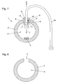
- Fig. 8 shows the outer shell 2 before the magnetic or magnetizable body 5 is inserted into the cavity 3 and the opening 4 is closed by means of the plug 6.
- This outer shell 2 according to Fig. 8 can in all embodiments according to the Fig. 2 to 7 be used.
- the magnetic or magnetizable body is arranged freely movable in the cavity 3. This allows him to align himself freely to magnetically secure the hollow body 1 in almost any position on an external magnet or magnetizable material.
- an external counterpart to the magnetic or magnetizable body 5 is in the Fig. 1 and 2
- a carrier body 22 is shown, which allows the hollow body 1 to be fastened at an almost arbitrary point on a piece 21 of the clothing of a dog trainer or another person.
- the in the Fig. 1 and 2 shown carrier body 22 is from the EP 2 255 617 B1 known. It can therefore be referred to its description to the corresponding text passages of this document.
- the carrier body 22 has at least one magnet 18.
- Magnets or bodies of magnetizable material which have already been disclosed can also be sewn in at fixed locations into the clothing of the dog trainer or another person working with the dog. Magnets or magnetizable material can of course be plugged into corresponding pockets of clothing or the like.
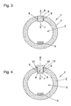
- Fig. 3 shows an inventive embodiment in which the stopper 6 is fixed only cohesively on the opening 4 surrounding edge 9 of the outer shell.
- the stopper 6 can be glued to the edge 9, vulcanized or fixed thereto by means of a melting process.
- the connection between stopper 6 and edge 9 is also designed so that stopper 6 can not be pushed out of opening 4 either in direction 7 into cavity 3 or in direction 9 out of cavity 3.
- Fig. 4 shows a variant in which the plug 6 is in turn secured in a form-fitting manner to the edge 9 of the outer shell 2.
- this is done via a thread 12 on the plug 6 and in the edge 9 of the outer shell 2.
- a corresponding thread 12 may already be provided in advance of the insertion of the plug 6 in the opening 4 at these two parts.
- it is also sufficient to prepare this thread 12 in advance on only one of the two parts, that is to say on the stopper 6 or on the edge 9, so that the thread is cut into the respective other part when the stopper 6 is screwed into the edge 9.
- the thread 12 is attached at least to the harder of the two parts mentioned.
- the plug 6 may at this an engagement or attack area for a tool such as a screwdriver slot, an external polygon or a Be provided inside polygon.
- a collar 10 is provided on the stopper 6. In principle, however, this can also be dispensed with, since the thread 12 alone generally already ensures that the stopper 6, when it is arranged in the opening 4, both in the direction 7 in the cavity 3 and in the direction 8 from the Cavity 3 addition, to which the opening 4 surrounding edge 9 of the outer shell 2 is sufficiently well secured.
- Fig. 5 shows a modified variant of the invention, based on the embodiment according to Fig. 2 ,
- the body of magnetic or magnetizable material 5 is not freely movable as in the other embodiments but attached to an extension 13 of the plug 6 and thus the plug 6 itself.
- the extension 13 can also be omitted or designed to be of different lengths.
- the magnetic or magnetizable body 5 is in any case favorably, as in Fig. 5 also shown, arranged as centrally as possible in the cavity 3. It can be rigidly attached to the extension 13 or to the plug 6, as shown here in the simple variant according to FIG Fig. 5 also realized.
- the plug 13 and the extension 13 could also have an internal cavity in which a corresponding body 5 of magnetic or magnetizable material is in turn mounted freely movable to turn in the polarity of an external magnetic field, for. B. a carrier body 22 to align.
- a carrier body 22 to align.
- Fig. 5 The positive fastening of the plug 6 to the edge 4 surrounding the opening 4 of the outer shell 2 in Fig. 5 is analogous to the embodiments according to Fig. 1 and 2 It does not need to be explained again. This also applies to the Fig. 6 and 7 , which also, if different than in Fig. 5 Type of modification of the variant according to Fig. 2 represent.
- Fig. 6 and 7 show embodiments of the invention, in which in or on the plug 6, a fastening device 14 for attaching an outside of the outer shell 2 can be arranged, preferably flexible, handle member 15 is arranged.
- the stopper 6 has an eyelet arranged on the outside as a fastening device 14, by means of which a corresponding grip element 15, shown schematically here in the form of a band loop, can be fastened.
- Fig. 7 the plug 6 as a fastening device 14 in the longitudinal direction of the plug 6 passed therethrough channel through which a cable used here as a flexible handle element 15 is passed. So that the grip element 15 can not slip out of the fastening device 14 forming the channel, its ends are knotted.
- corresponding collars 10 may additionally be provided on otherwise already fixed plugs 6 in order to achieve an additional form-fitting support, at least in one of the two directions 7 and 8.
- the variant of the attachment of the magnetic or magnetizable body 5 on the plug 6 and its extension 13 can ultimately at all other embodiments shown here instead of the freely movable body 5 in the cavity 3 can be realized.
Landscapes
- Life Sciences & Earth Sciences (AREA)
- Environmental Sciences (AREA)
- Health & Medical Sciences (AREA)
- General Health & Medical Sciences (AREA)
- Physical Education & Sports Medicine (AREA)
- Animal Behavior & Ethology (AREA)
- Zoology (AREA)
- Animal Husbandry (AREA)
- Biodiversity & Conservation Biology (AREA)
- Magnetic Treatment Devices (AREA)
- Closures For Containers (AREA)
Applications Claiming Priority (1)
| Application Number | Priority Date | Filing Date | Title |
|---|---|---|---|
| DE202014000903.1U DE202014000903U1 (de) | 2014-02-04 | 2014-02-04 | Hohlkörper |
Publications (3)
| Publication Number | Publication Date |
|---|---|
| EP2901854A1 true EP2901854A1 (fr) | 2015-08-05 |
| EP2901854B1 EP2901854B1 (fr) | 2024-03-13 |
| EP2901854C0 EP2901854C0 (fr) | 2024-03-13 |
Family
ID=50556307
Family Applications (1)
| Application Number | Title | Priority Date | Filing Date |
|---|---|---|---|
| EP15000184.0A Active EP2901854B1 (fr) | 2014-02-04 | 2015-01-23 | Corps creux |
Country Status (2)
| Country | Link |
|---|---|
| EP (1) | EP2901854B1 (fr) |
| DE (1) | DE202014000903U1 (fr) |
Cited By (1)
| Publication number | Priority date | Publication date | Assignee | Title |
|---|---|---|---|---|
| USD990067S1 (en) | 2021-06-15 | 2023-06-20 | Starmark Pet Products, Inc. | Pet toy |
Families Citing this family (1)
| Publication number | Priority date | Publication date | Assignee | Title |
|---|---|---|---|---|
| AT515786B1 (de) * | 2014-08-19 | 2015-12-15 | Brummer Philippe | Beißkorb |
Citations (4)
| Publication number | Priority date | Publication date | Assignee | Title |
|---|---|---|---|---|
| US5542376A (en) * | 1995-01-23 | 1996-08-06 | Udelle; Steven D. | Animal entertainment and exercise stimulator |
| US20100147228A1 (en) * | 2008-12-16 | 2010-06-17 | Elation Inc. | Combination Of A Carrying Device And At Least One Dog Toy |
| EP2255617B1 (fr) | 2010-07-06 | 2012-10-03 | Markus Schwendinger | Dispositif pour l'éducation de chiens avec un corps pour mâcher |
| US20130055965A1 (en) * | 2011-09-01 | 2013-03-07 | Jw Pet Company, Inc. | Treat dispenser |
Family Cites Families (4)
| Publication number | Priority date | Publication date | Assignee | Title |
|---|---|---|---|---|
| US6557496B2 (en) * | 2001-02-02 | 2003-05-06 | Marketing And Creative Sales, Inc. | Treat dispensing toy |
| US7389748B2 (en) * | 2003-03-25 | 2008-06-24 | Canine Genius | Food dispensing interlocking animal toy system |
| US20120073513A1 (en) * | 2010-09-24 | 2012-03-29 | Innovative Design & Sourcing, LLC | Shaggy pet toy and method of construction |
| DE202010015821U1 (de) * | 2010-11-29 | 2011-03-10 | Aps Automatisierte Produktions-Systeme Ges. M.B.H. | Bestätigungselement für die Hundeausbildung |
-
2014
- 2014-02-04 DE DE202014000903.1U patent/DE202014000903U1/de not_active Expired - Lifetime
-
2015
- 2015-01-23 EP EP15000184.0A patent/EP2901854B1/fr active Active
Patent Citations (4)
| Publication number | Priority date | Publication date | Assignee | Title |
|---|---|---|---|---|
| US5542376A (en) * | 1995-01-23 | 1996-08-06 | Udelle; Steven D. | Animal entertainment and exercise stimulator |
| US20100147228A1 (en) * | 2008-12-16 | 2010-06-17 | Elation Inc. | Combination Of A Carrying Device And At Least One Dog Toy |
| EP2255617B1 (fr) | 2010-07-06 | 2012-10-03 | Markus Schwendinger | Dispositif pour l'éducation de chiens avec un corps pour mâcher |
| US20130055965A1 (en) * | 2011-09-01 | 2013-03-07 | Jw Pet Company, Inc. | Treat dispenser |
Cited By (1)
| Publication number | Priority date | Publication date | Assignee | Title |
|---|---|---|---|---|
| USD990067S1 (en) | 2021-06-15 | 2023-06-20 | Starmark Pet Products, Inc. | Pet toy |
Also Published As
| Publication number | Publication date |
|---|---|
| EP2901854B1 (fr) | 2024-03-13 |
| DE202014000903U1 (de) | 2014-04-03 |
| EP2901854C0 (fr) | 2024-03-13 |
Similar Documents
| Publication | Publication Date | Title |
|---|---|---|
| DE102015004184B4 (de) | Vorrichtung zur Befestigung einer Leitungsführungskette | |
| EP2550860B1 (fr) | Dispositif pour l'éducation canine avec un corps à mordre | |
| DE2818222A1 (de) | Aufrollbare koppelleine | |
| DE102008063897A1 (de) | Kombination aus einer Tragevorrichtung und mindestens einem Motivationsgegenstand für Hunde | |
| EP2901854B1 (fr) | Corps creux | |
| EP1097731B1 (fr) | Flexible nunchaku et son utilisation | |
| DE102017123784B4 (de) | Universelle Einspannung zur Befestigung beliebiger Gegenstände an einer Angelschnur | |
| DE102010037762A1 (de) | Hufeisen für Reittierhufe, insbesondere für Pferde | |
| DE112017001760T5 (de) | Atemwegsventil für unregelmässig geformte atemwege | |
| EP3014989A1 (fr) | Systeme de harnais pour animaux | |
| DE68901697T2 (de) | Vorrichtung zur postoperativen befestigung einer seitlichen kolostomie. | |
| EP3494782B1 (fr) | Anneau nasal pour animaux | |
| DE3123880A1 (de) | Markierungsstange | |
| DE202007014880U1 (de) | Lösbare Verbindung für Gehhilfen u.dgl. | |
| DE202008010203U1 (de) | Atemhilfeset und Atemhilfesystem | |
| DE102010018897B3 (de) | Dressurhalsband, insbesondere für Hunde | |
| DE3240683A1 (de) | Hohlseil | |
| DE3306320A1 (de) | Schlaufe mit befestigungsvorrichtung | |
| DE102004051151B3 (de) | Führvorrichtung für Tiere, insbesondere Hunde | |
| WO2013064353A1 (fr) | Mors de filet pour cheval comportant une ou deux articulations et procédé de fabrication d'un tel mors de filet | |
| DE2053937C3 (de) | Vorrichtung zum Befestigen eines Knopfes oder dergleichen an flächigem Material, z.B. einem Gewebe | |
| DE1012491B (de) | Schwimmer mit Tiefenlot fuer die Angelfischerei | |
| DE202016005094U1 (de) | Vorrichtung zur Erstellung einer magnetorientierten, formschlüssigen Verbindung | |
| EP4304411A1 (fr) | Support de queue de cheval | |
| EP3443859A1 (fr) | Fermeture à crochets et sac à dos |
Legal Events
| Date | Code | Title | Description |
|---|---|---|---|
| PUAI | Public reference made under article 153(3) epc to a published international application that has entered the european phase |
Free format text: ORIGINAL CODE: 0009012 |
|
| 17P | Request for examination filed |
Effective date: 20150123 |
|
| AK | Designated contracting states |
Kind code of ref document: A1 Designated state(s): AL AT BE BG CH CY CZ DE DK EE ES FI FR GB GR HR HU IE IS IT LI LT LU LV MC MK MT NL NO PL PT RO RS SE SI SK SM TR |
|
| AX | Request for extension of the european patent |
Extension state: BA ME |
|
| 17P | Request for examination filed |
Effective date: 20151214 |
|
| RBV | Designated contracting states (corrected) |
Designated state(s): AL AT BE BG CH CY CZ DE DK EE ES FI FR GB GR HR HU IE IS IT LI LT LU LV MC MK MT NL NO PL PT RO RS SE SI SK SM TR |
|
| STAA | Information on the status of an ep patent application or granted ep patent |
Free format text: STATUS: EXAMINATION IS IN PROGRESS |
|
| 17Q | First examination report despatched |
Effective date: 20171128 |
|
| GRAP | Despatch of communication of intention to grant a patent |
Free format text: ORIGINAL CODE: EPIDOSNIGR1 |
|
| STAA | Information on the status of an ep patent application or granted ep patent |
Free format text: STATUS: GRANT OF PATENT IS INTENDED |
|
| INTG | Intention to grant announced |
Effective date: 20231026 |
|
| GRAS | Grant fee paid |
Free format text: ORIGINAL CODE: EPIDOSNIGR3 |
|
| GRAA | (expected) grant |
Free format text: ORIGINAL CODE: 0009210 |
|
| STAA | Information on the status of an ep patent application or granted ep patent |
Free format text: STATUS: THE PATENT HAS BEEN GRANTED |
|
| AK | Designated contracting states |
Kind code of ref document: B1 Designated state(s): AL AT BE BG CH CY CZ DE DK EE ES FI FR GB GR HR HU IE IS IT LI LT LU LV MC MK MT NL NO PL PT RO RS SE SI SK SM TR |
|
| REG | Reference to a national code |
Ref country code: GB Ref legal event code: FG4D Free format text: NOT ENGLISH |
|
| REG | Reference to a national code |
Ref country code: CH Ref legal event code: EP |
|
| REG | Reference to a national code |
Ref country code: DE Ref legal event code: R096 Ref document number: 502015016780 Country of ref document: DE |
|
| REG | Reference to a national code |
Ref country code: IE Ref legal event code: FG4D Free format text: LANGUAGE OF EP DOCUMENT: GERMAN |
|
| U01 | Request for unitary effect filed |
Effective date: 20240409 |
|
| U07 | Unitary effect registered |
Designated state(s): AT BE BG DE DK EE FI FR IT LT LU LV MT NL PT SE SI Effective date: 20240416 |
|
| PG25 | Lapsed in a contracting state [announced via postgrant information from national office to epo] |
Ref country code: GR Free format text: LAPSE BECAUSE OF FAILURE TO SUBMIT A TRANSLATION OF THE DESCRIPTION OR TO PAY THE FEE WITHIN THE PRESCRIBED TIME-LIMIT Effective date: 20240614 |
|
| PG25 | Lapsed in a contracting state [announced via postgrant information from national office to epo] |
Ref country code: HR Free format text: LAPSE BECAUSE OF FAILURE TO SUBMIT A TRANSLATION OF THE DESCRIPTION OR TO PAY THE FEE WITHIN THE PRESCRIBED TIME-LIMIT Effective date: 20240313 Ref country code: RS Free format text: LAPSE BECAUSE OF FAILURE TO SUBMIT A TRANSLATION OF THE DESCRIPTION OR TO PAY THE FEE WITHIN THE PRESCRIBED TIME-LIMIT Effective date: 20240613 |
|
| PG25 | Lapsed in a contracting state [announced via postgrant information from national office to epo] |
Ref country code: ES Free format text: LAPSE BECAUSE OF FAILURE TO SUBMIT A TRANSLATION OF THE DESCRIPTION OR TO PAY THE FEE WITHIN THE PRESCRIBED TIME-LIMIT Effective date: 20240313 |
|
| PG25 | Lapsed in a contracting state [announced via postgrant information from national office to epo] |
Ref country code: RS Free format text: LAPSE BECAUSE OF FAILURE TO SUBMIT A TRANSLATION OF THE DESCRIPTION OR TO PAY THE FEE WITHIN THE PRESCRIBED TIME-LIMIT Effective date: 20240613 Ref country code: NO Free format text: LAPSE BECAUSE OF FAILURE TO SUBMIT A TRANSLATION OF THE DESCRIPTION OR TO PAY THE FEE WITHIN THE PRESCRIBED TIME-LIMIT Effective date: 20240613 Ref country code: HR Free format text: LAPSE BECAUSE OF FAILURE TO SUBMIT A TRANSLATION OF THE DESCRIPTION OR TO PAY THE FEE WITHIN THE PRESCRIBED TIME-LIMIT Effective date: 20240313 Ref country code: GR Free format text: LAPSE BECAUSE OF FAILURE TO SUBMIT A TRANSLATION OF THE DESCRIPTION OR TO PAY THE FEE WITHIN THE PRESCRIBED TIME-LIMIT Effective date: 20240614 Ref country code: ES Free format text: LAPSE BECAUSE OF FAILURE TO SUBMIT A TRANSLATION OF THE DESCRIPTION OR TO PAY THE FEE WITHIN THE PRESCRIBED TIME-LIMIT Effective date: 20240313 |
|
| PG25 | Lapsed in a contracting state [announced via postgrant information from national office to epo] |
Ref country code: IS Free format text: LAPSE BECAUSE OF FAILURE TO SUBMIT A TRANSLATION OF THE DESCRIPTION OR TO PAY THE FEE WITHIN THE PRESCRIBED TIME-LIMIT Effective date: 20240713 |
|
| PG25 | Lapsed in a contracting state [announced via postgrant information from national office to epo] |
Ref country code: SM Free format text: LAPSE BECAUSE OF FAILURE TO SUBMIT A TRANSLATION OF THE DESCRIPTION OR TO PAY THE FEE WITHIN THE PRESCRIBED TIME-LIMIT Effective date: 20240313 |
|
| PG25 | Lapsed in a contracting state [announced via postgrant information from national office to epo] |
Ref country code: PL Free format text: LAPSE BECAUSE OF FAILURE TO SUBMIT A TRANSLATION OF THE DESCRIPTION OR TO PAY THE FEE WITHIN THE PRESCRIBED TIME-LIMIT Effective date: 20240313 |
|
| PG25 | Lapsed in a contracting state [announced via postgrant information from national office to epo] |
Ref country code: SK Free format text: LAPSE BECAUSE OF FAILURE TO SUBMIT A TRANSLATION OF THE DESCRIPTION OR TO PAY THE FEE WITHIN THE PRESCRIBED TIME-LIMIT Effective date: 20240313 |
|
| PG25 | Lapsed in a contracting state [announced via postgrant information from national office to epo] |
Ref country code: SM Free format text: LAPSE BECAUSE OF FAILURE TO SUBMIT A TRANSLATION OF THE DESCRIPTION OR TO PAY THE FEE WITHIN THE PRESCRIBED TIME-LIMIT Effective date: 20240313 Ref country code: SK Free format text: LAPSE BECAUSE OF FAILURE TO SUBMIT A TRANSLATION OF THE DESCRIPTION OR TO PAY THE FEE WITHIN THE PRESCRIBED TIME-LIMIT Effective date: 20240313 Ref country code: RO Free format text: LAPSE BECAUSE OF FAILURE TO SUBMIT A TRANSLATION OF THE DESCRIPTION OR TO PAY THE FEE WITHIN THE PRESCRIBED TIME-LIMIT Effective date: 20240313 Ref country code: PL Free format text: LAPSE BECAUSE OF FAILURE TO SUBMIT A TRANSLATION OF THE DESCRIPTION OR TO PAY THE FEE WITHIN THE PRESCRIBED TIME-LIMIT Effective date: 20240313 Ref country code: IS Free format text: LAPSE BECAUSE OF FAILURE TO SUBMIT A TRANSLATION OF THE DESCRIPTION OR TO PAY THE FEE WITHIN THE PRESCRIBED TIME-LIMIT Effective date: 20240713 |
|
| REG | Reference to a national code |
Ref country code: DE Ref legal event code: R097 Ref document number: 502015016780 Country of ref document: DE |
|
| U20 | Renewal fee for the european patent with unitary effect paid |
Year of fee payment: 11 Effective date: 20241205 |
|
| PLBE | No opposition filed within time limit |
Free format text: ORIGINAL CODE: 0009261 |
|
| STAA | Information on the status of an ep patent application or granted ep patent |
Free format text: STATUS: NO OPPOSITION FILED WITHIN TIME LIMIT |
|
| 26N | No opposition filed |
Effective date: 20241216 |
|
| PG25 | Lapsed in a contracting state [announced via postgrant information from national office to epo] |
Ref country code: MC Free format text: LAPSE BECAUSE OF FAILURE TO SUBMIT A TRANSLATION OF THE DESCRIPTION OR TO PAY THE FEE WITHIN THE PRESCRIBED TIME-LIMIT Effective date: 20240313 |
|
| GBPC | Gb: european patent ceased through non-payment of renewal fee |
Effective date: 20250123 |
|
| PG25 | Lapsed in a contracting state [announced via postgrant information from national office to epo] |
Ref country code: GB Free format text: LAPSE BECAUSE OF NON-PAYMENT OF DUE FEES Effective date: 20250123 |
|
| PG25 | Lapsed in a contracting state [announced via postgrant information from national office to epo] |
Ref country code: IE Free format text: LAPSE BECAUSE OF NON-PAYMENT OF DUE FEES Effective date: 20250123 |
|
| U20 | Renewal fee for the european patent with unitary effect paid |
Year of fee payment: 12 Effective date: 20251219 |
|
| REG | Reference to a national code |
Ref country code: CH Ref legal event code: U11 Free format text: ST27 STATUS EVENT CODE: U-0-0-U10-U11 (AS PROVIDED BY THE NATIONAL OFFICE) Effective date: 20260201 |
|
| PGFP | Annual fee paid to national office [announced via postgrant information from national office to epo] |
Ref country code: CH Payment date: 20260201 Year of fee payment: 12 Ref country code: CZ Payment date: 20260109 Year of fee payment: 12 |