EP2901860B1 - Diviseuse pour pâtes - Google Patents
Diviseuse pour pâtes Download PDFInfo
- Publication number
- EP2901860B1 EP2901860B1 EP15152419.6A EP15152419A EP2901860B1 EP 2901860 B1 EP2901860 B1 EP 2901860B1 EP 15152419 A EP15152419 A EP 15152419A EP 2901860 B1 EP2901860 B1 EP 2901860B1
- Authority
- EP
- European Patent Office
- Prior art keywords
- dough
- module
- dividing machine
- feed chamber
- machine according
- Prior art date
- Legal status (The legal status is an assumption and is not a legal conclusion. Google has not performed a legal analysis and makes no representation as to the accuracy of the status listed.)
- Active
Links
Images



Classifications
-
- A—HUMAN NECESSITIES
- A21—BAKING; EDIBLE DOUGHS
- A21C—MACHINES OR EQUIPMENT FOR MAKING OR PROCESSING DOUGHS; HANDLING BAKED ARTICLES MADE FROM DOUGH
- A21C5/00—Dough-dividing machines
- A21C5/02—Dough-dividing machines with division boxes and ejection plungers
- A21C5/04—Dough-dividing machines with division boxes and ejection plungers with division boxes in a revolving body with radially-working pistons
Definitions
- the invention relates to a dough dividing machine according to the preamble of claim 1. Furthermore, the invention relates to a dough processing plant according to claim 15.
- a dough dividing machine of the type mentioned is known from the EP 0 494 367 A1 and the WO 03/022 057 A2 ,
- the AT 13 119 U1 shows a portioning unit for Teigteilmaschinen.
- EP0494367 A1 discloses in connection with all features of the preamble of claim 1.
- a modular design of the dough divider improves the solubility of individual units of the dough divider.
- the dough dividing machine has at least two of the following modules: a feed chamber module formed by a feed chamber container, a hopper module formed by a dough addition funnel, a piston module formed by a dough feed plunger, and a mouthpiece module formed by a dough mouthpiece.
- a quick connection device for assembly and disassembly of the modules is provided.
- each of the modules is a quick connection device assigned.
- the quick connect devices may be quick release means or other suitable quick connect devices.
- a modular disassembly of the feed chamber module, the piston module and the mouthpiece module from the Teigteilmaschine according to claims 2, 3 and 4 allows separate cleaning, maintenance or repair of each removed module.
- the modules remaining in the dough dividing machine are more accessible and therefore also easier to clean, maintain or repair.
- modular removal is meant that the respective module is detachable as a coherent unit from the Teigteilmaschine. In the event of a module failure, the affected module would be replaceable without the need to replace undamaged modules.
- a Teigteilmaschine according to claim 5 allows an arrangement of the modules in a common frame. As a result, the structural design of the dough dividing machine is further simplified.
- a dough dividing machine according to claim 6 provides the possibility of cleaning, repairing and / or servicing a module without the need to remove or displace another module.
- a product or format change can also be simplified.
- the frame may preferably serve as a guide for a displacement movement of the individual modules.
- the individual modules can be connected to the frame by the quick connection device.
- a guided displaceable feed chamber module according to claim 7 makes it possible to quickly and easily access the feed chamber for cleaning or maintenance purposes.
- the mouthpiece module is preferably pivotable about a mouthpiece pivot axis.
- the funnel module is preferably pivotable about a funnel pivot axis.
- a Teigteilmaschine according to claims 11 and 12 each allows a secure guide the displacement of the piston module and the Zu20740 module by linear guides.
- a linear actuator as Hubverlagerungsantrieb with a linearly driven drive component according to claim 13 provides new degrees of freedom with respect to the arrangement of the components of the Teigteilmaschine.
- a lever linkage which is used in dough dividing machines of the prior art for the transmission of a rotary drive in a drive movement for stroke displacement of the dough supply piston, is eliminated.
- the linear actuator can be made compact.
- On a deflection gear, which converts a rotary drive movement in a linear motion can be dispensed with. Via the linear actuator, a stroke displacement of the dough supply piston can take place at a defined predetermined speed.
- a defined velocity profile of the stroke displacement of the dough supply piston is possible via a corresponding control of the linear actuator.
- a maximum stroke displacement speed can be preset depending on the dough to be processed or depending on the size of the dough portion to be divided or depending on the amount of the dough to be processed at the same time.
- a speed profile of the stroke displacement can be carried out, for example, with a rising and a falling speed ramp.
- Via the linear actuator a total stroke width of the stroke displacement can be specified exactly. This stroke can also be given to the Dough portion to be adjusted exactly.
- the drive component is connected via a deflection connection with the dough supply piston.
- the drive component may be linearly connected to the dough supply piston.
- Such compounds of the drive component with the dough-ZuEnglishkolben stellen variants that can be realized according to the space requirements.
- the drive component When the drive component is linearly connected to the dough supply piston, the drive component and the dough supply piston extend along a common linear displacement axis.
- the Hubverlagerungsantrieb can be designed as a linear direct drive, in particular without mechanical component, or can be designed as a double rack-and-pinion with servomotor.
- the servomotor can be equipped with a frequency converter.
- a continuously variable pressure can be set, which is exerted on the feed piston on the dough.
- a separate pressure sensor for measuring the dough pressure may be provided, but is not mandatory, since a servomotor current can be tapped as a measure of the pressure exerted on the dough on the dough.
- This pressure can be individually adapted to each dough recipe.
- a pressure adjustment can be made for example in dough weight inaccuracies. It can be given a maximum pressure, which exerts the feed piston on the dough. An undesirable destruction of dough due to excessive pressure exerted by the Zuzhoukolben is thereby avoided.
- a path of the Zugarkolbens can be adjusted continuously with the help of the servo drive pressure-independent.
- a rack-and-pinion drive with a servomotor is known, for example, from the complete catalog lifgo® & lean SL® 5 from LEANTECHNIK AG, version 07.2013, in particular on page 26.
- a guide function can be completely taken over by an integrated mounting of the lifting gear.
- a suitable linear direct drive is known from the brochure "Linear direct drives - three-phase synchronous linear motors - LP series with liquid or air cooling" by Oswald Elektromotoren GmbH, version 0413.
- An electromechanical actuator according to claim 14 is a preferred drive variant in terms of its compact design and the achievable lifting force.
- the drive component can be driven in the linear actuator via an internal spindle drive.
- the dough located in the dough supply chamber is further conveyed by the dough supply piston through the dough mouthpiece towards at least one dough measuring chamber for prescribing a dough portion.
- the dough supply piston is displaceable between a release position in which the dough supply piston releases the dough supply chamber for feeding dough and a feed position in which the dough supply piston a content of the dough supply chamber through the dough mouthpiece towards at least a dough measuring chamber for specifying a dough portion promotes.
- a plurality of dough measuring chambers allows a parallel specification of a corresponding number of dough portions.
- the dough supply piston may also be designed as a piston in a plurality of dough measuring chambers.
- the driven dough supply piston, the linear guide for guiding a stroke displacement of the Teigzu Switzerlandkolbens in a management level and the linear actuator forms an assembly.
- the extent of this assembly is perpendicular to the leadership advantageously not more than five times as large as an extension of the Zuzhoukolbens perpendicular to the management level.
- Such an assembly uses the linear actuator to a particularly compact arrangement. It can be saved within the dough dividing machine so space, which is available for other components. As far as several dough measuring chambers are used, these dough measuring chambers can lie in the management level of the assembly. It is advantageous if the linear actuator is arranged perpendicular to the guide plane offset from the dough supply piston. Alternatively, the linear actuator may be arranged in the guide plane.
- Such arrangement variants have proven to be suitable alternatives depending on the space requirements.
- a linear direct drive in particular without mechanical components, or a double rack and pinion gear with servomotor can be used.
- the dough dividing machine according to the invention can be used according to claim 15 in a dough processing plant.
- a dough divider 1 has a in the Fig. 1 shown funnel module formed by a dough addition funnel 2, can be supplied by the dough from above manually or automatically.
- a feed chamber module formed by a feed chamber container 3.
- the inside of the feed chamber container 3 forms a dough supply chamber 4.
- a piston module which is formed by a dough-feeding piston 6, which is also indicated by dashed lines.
- a mouthpiece module is arranged, which is formed by a dough mouthpiece 7.
- quick connection means for assembly and disassembly of the funnel module 4, the piston module 6 and the mouthpiece module 7 are provided.
- Each of the modules is assigned a quick connection device.
- the quick-connection devices are preferably tensioning closures known per se.
- Other quick connection devices, by means of which the modules can be solved quickly and without additional tools from the dough dividing machine 1, can alternatively be used.
- the dough-feeding piston 6 is stroke-displaceable for feeding the dough located in the dough-feeding chamber 4 to the mouthpiece 7.
- the dough-feeding piston 6 is supported by a piston-carrying device 32 and detachably held.
- a connection between dough supply piston 6 and piston support device 32 is provided by a suitable quick connection means, for example a screw, latch or clamp connection.
- the dough supply piston 6 is displaceable hub between a not in the Fig. 1 shown and opposite the position Fig. 1 shifted to the right release position in which the dough-feeding piston 6, the dough-supplying chamber 4 for feeding dough from the dough addition funnel second releases, and one in the Fig. 1 shown feed position in which the dough-Zuzhoukolben 6 a content of the dough-supplying chamber 4, ie the dough located there, through a transfer channel 8 through the dough-mouthpiece 7 continues to dough measuring chambers 9 for the specification of dough portions.
- the transfer channel 8 is in the Fig. 1 shown schematically as a straight channel. In fact, the transfer channel 8 tapers conically in the dough conveying direction.
- the dough supply piston 6 has a dough scraper edge. By the dough scraper edge, which is arranged on the dough-feeding piston 6 such that it points in the direction of mouthpiece module 7, an unwanted entrainment of dough upon displacement of the dough-feeding piston 6 is prevented from the feed position back to the release position.
- the dough divider 1 has a plurality of transfer channels 8 in the dough mouthpiece 7, which are perpendicular to the plane of the Fig. 1 are arranged side by side, for example, 4, 5, 6, 7, 8, 10, 12, 15, 20 or more transfer channels 8.
- the transfer channels 8 are assigned to specify a corresponding number of dough portions, the dough measuring chambers 9 in a corresponding number.
- the dough measuring chambers 9 are arranged in a measuring drum 10 which has a plurality of rows of corresponding dough measuring chambers 9 distributed in the circumferential direction about a drum axis 11 of the measuring drum 10.
- the dough measuring chambers 9 are driven to rotate about the drum axis 11.
- the measuring drum 10 is designed to be open to one side, as in particular in the embodiment to be described later Fig. 7 is shown. As a result, the interior of the measuring drum 10 is easily accessible.
- a conveying device 13 which may be a conveyor belt or a number of individual conveyor belts corresponding to the number of dough measuring chambers 9, to an operating drum 14, in which the dough portions be worked in a conventional manner.
- the knitted dough portions are then fed via a further conveyor 15, which basically can correspond to the conveyor 13, a further dough processing.
- a Hubverlagerungsantrieb 16 of the Teigzu Foodkolbens 6 is designed as a linear actuator with a linearly driven drive component 17 in the form of a piston rod.
- the piston rod 17 is in the Fig. 1 shown retracted.
- the piston rod 17 is guided via a guide bush 18, which is connected to the frame displacement with the Hubverlagerungsantrieb 16.
- a free end of the drive component 17 carries a mounting lug 19, which is connected via a deflection link 20 with a guide carriage 21, which in turn is fixedly connected to the dough supply piston 6.
- the guide carriage 21 is part of a linear guide 22 for guiding the stroke displacement of the Teigzu Foodkolbens 6 in the guide plane 5.
- the linear guide 22 includes two parallel in the guide plane 5 juxtaposed guide bushings 23, of which in the Fig. 1 only the one facing the viewer can be seen.
- the guide bushes 23 and the Zutechnology screening matterer 3 run on guide rods 24, whose two ends are fixedly connected via bearing blocks 25, 26 with a frame 27 of the dough dividing machine 1.
- the linear actuator 16 is designed as an electromechanical actuator.
- the drive component 17 thus represents an electromechanical actuating component.
- the linear actuator 16 can be designed as an electromechanical actuating cylinder.
- a linear drive for the drive component 17 can take place via an internal spindle drive of the linear actuator 16.
- the linear actuator 16 is designed as a servo-linear actuator with a servo gear.
- a stroke displacement of the dough supply piston 6 takes place as follows: As soon as the dough supply chamber 4 is filled with dough and a row of empty dough measuring chambers 9 is in alignment with the transfer channels 8 by corresponding rotation of the measuring drum 10, the linear actuator 16 is actuated and the dough Zuglasskolben 6 is from the release position in the feed position to Fig. 1 transferred. For this purpose, the drive component 17 of the linear actuator 16 is retracted. In this case, the drive component 17 runs in the guide bushing 18 and parallel thereto, the guide carriage 21 runs with the guide bushes 23 on the guide rods 24. A in the Fig.
- a linear guide of the drive component 17 or of the dough supply piston 6 can also take place via another embodiment of a linear guide, for example via a linear sliding guide, for. B. in the form of a dovetail groove, or a linear roller guide.
- a linear sliding guide for. B. in the form of a dovetail groove, or a linear roller guide.
- the linear actuator 16 may also be another form of linear drive are used, for. B. a linear direct drive or a double rack and pinion with servomotor.
- a pneumatic cylinder or a hydraulic cylinder can also be used.
- the feed chamber module 3 can be displaced relative to the frame 27 when the carriage 21 is retracted into the release position, guided over the guide rods 24, so that the dough supply chamber 4, as in FIG Fig. 7 shown, freely accessible.
- the dough supply chamber 4 is mounted on the guide rods 24 via bearing bushes 28.
- Fig. 7 shows the feed chamber module 3 in the displaced position.
- the feed chamber module 3 can also be displaceable relative to the dough addition funnel 2.
- the linear guide 22 serves both to guide the stroke displacement of the piston module 6 and to guide the displacement of the feed chamber module. 3
- the mouthpiece module 7 is displaced relative to the feed chamber module 3.
- the mouthpiece module 7 is pivotable about a mouthpiece pivot axis 29.
- the mouthpiece module 7 is guided relative to the feed chamber module 3 pivotally displaceable.
- the funnel module 2 is in Fig. 7 also shown in a relative to the feed chamber module 3 displaced position.
- the hopper module 2 is guided relative to the feed chamber module 3 guided pivotable about a hopper pivot axis 30.
- the feed chamber module 3, the funnel module 2, the piston module 6 and the mouthpiece module 7 are each independently displaceable guided relative to the frame 27.
- the frame 27 is for reasons of clarity in Fig. 7 not shown.
- piston module 6 and the mouthpiece module 7 are modularly removable from the dough dividing machine 1.
- the mouthpiece module 7 can be replaced by the modular removability in a simple manner by another mouthpiece module, which has a different Reihmaschine or a different number of transfer channels 8. Segment-wise blocking of desired transfer channels 8 can be achieved by the absence of corresponding transfer channels 8. Due to the removability and interchangeability of the mouthpiece module 7 consequently a flexible adaptation of the dough dividing machine 1 to different requirements is made possible.
- the feed chamber module 3, the piston module 6 and the funnel module 2 are easily replaced by modular removability by differently shaped modules, whereby a flexible adaptation of the dough dividing machine 1 is further improved to various requirements.
- two power clamps are provided, which press the supply chamber module 3 against the mouthpiece module 7 with a defined force. As a result, an incorrect operation is effectively prevented, which could lead to excessive dough leakage.
- more than two power clamps or even a single power clamp can be provided.
- the modular design of the dough dividing machine 1 simplifies in particular the cleaning of the dough dividing machine 1, wherein different cleaning stages are conceivable.
- a cleaning of the dough dividing machine 1 can take place without the modules 2, 3, 6, 7 having to be removed, improved accessibility being ensured by a guided displaceability of the modules 2, 3, 6, 7.
- individual modules, in particular the modules 2, 7 can be pivoted.
- individual modules, in particular the modules 6, 7 are modularly removed from the dough dividing machine. No tools are needed to move, swivel and remove. Disassembly and assembly is enabled by means of the quick connectors.
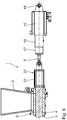
- Fig. 6 shows an alternative arrangement of the linear actuator 16 to the Teigzu Foodkolben 6. Components which correspond to those described above with reference to the Fig. 1 to 5 have already been explained, the same reference numbers and will not be discussed again in detail.
- the alternative arrangement according to Fig. 6 is also formed like a module and comprises a feed chamber module 3, a funnel module 2, a piston module 6 and a mouthpiece module. 7
- the linear actuator 16 is also arranged in the guide plane 5 of the dough supply piston 6.
- the drive component 17 acts directly on the carriage 21.
- the linear guide 22 is in the Fig. 6 indicated schematically and broken.
- the mounting lug 19 may be connected directly to the carriage 21 and dock on this.
Landscapes
- Life Sciences & Earth Sciences (AREA)
- Engineering & Computer Science (AREA)
- Food Science & Technology (AREA)
- Manufacturing And Processing Devices For Dough (AREA)
Claims (15)
- Diviseuse de pâte (1)- avec une trémie d'alimentation en pâte (2),- avec un récipient à compartiment d'amenée (3) avec un compartiment d'amenée de pâte (4) situé à la sortie de la trémie d'alimentation en pâte (2),- avec une buse d'éjection de pâte (7) en aval du compartiment d'amenée de pâte (4) sur le trajet de transport de la pâte, et- avec au moins un piston d'amenée de pâte (6) mobile sur une course de piston pour refouler la pâte se trouvant dans le compartiment d'amenée de pâte (4) vers la buse d'éjection de pâte (7),caractérisée en ce que- ladite diviseuse de pâte est réalisée de manière modulaire pour en faciliter le démontage, et en ce qu'elle présente au moins deux des modules ci-dessous :-- un module de compartiment d'amenée (3) formé par le récipient à compartiment d'amenée (3),-- un module de trémie (2) formé par la trémie d'alimentation en pâte (2),-- un module de piston (6) formé par le piston d'amenée de pâte (6), et-- un module de buse (7) formé par la buse d'éjection de pâte (7),- au moins un dispositif de raccord rapide étant prévu pour le montage et le démontage des modules.
- Diviseuse de pâte selon la revendication 1, caractérisée en ce que le module de compartiment d'amenée (3) est démontable modulairement de la diviseuse de pâte (1).
- Diviseuse de pâte selon la revendication 1 ou 2, caractérisée en ce que le module de piston (6) est retirable modulairement de la diviseuse de pâte (1).
- Diviseuse de pâte selon l'une des revendications précédentes, caractérisée en ce que le module de buse (7) est retirable modulairement de la diviseuse de pâte (1).
- Diviseuse de pâte selon l'une des revendications précédentes, caractérisée en ce que ladite diviseuse de pâte (1) comporte un châssis (27).
- Diviseuse de pâte selon la revendication 5, caractérisée en ce que le module de compartiment d'amenée (3), le module de trémie (2), le module de piston (6) et le module de buse (7) peuvent respectivement être déplacés indépendamment les uns des autres par rapport au châssis (27).
- Diviseuse de pâte selon la revendication 5, caractérisée en ce que le module de compartiment d'amenée (3) peut être déplacé par rapport au châssis (27).
- Diviseuse de pâte selon l'une des revendications précédentes, caractérisée en ce que le module de compartiment d'amenée (3) peut être déplacé par rapport à la trémie d'alimentation en pâte (2).
- Diviseuse de pâte selon l'une des revendications précédentes, caractérisée en ce que le module de buse (7) peut être déplacé par rapport au module de compartiment d'amenée (3).
- Diviseuse de pâte selon l'une des revendications précédentes, caractérisée en ce que le module de trémie (2) peut être déplacé par rapport au module de compartiment d'amenée (3).
- Diviseuse de pâte selon l'une des revendications précédentes, caractérisée par un guidage linéaire (22) pour le guidage d'une course du module de piston (6).
- Diviseuse de pâte selon les revendications 1 et 7, caractérisée par un guidage linéaire (22) pour le guidage d'un déplacement du module de compartiment d'amenée (3).
- Diviseuse de pâte selon l'une des revendications précédentes, caractérisée en ce qu'un entraînement de course de piston (16) du piston d'amenée de pâte (6) est réalisé comme actionneur linéaire avec un composant d'entraînement (17) entraîné linéairement.
- Diviseuse de pâte selon la revendication 13, caractérisée en ce que l'actionneur linéaire (16) est réalisé comme actionneur électromécanique, le composant d'entraînement (17) étant alors réalisé comme composant de réglage électromécanique.
- Installation pour le traitement de pâte avec une diviseuse de pâte selon l'une des revendications 1 à 14.
Applications Claiming Priority (1)
| Application Number | Priority Date | Filing Date | Title |
|---|---|---|---|
| DE102014201518.9A DE102014201518A1 (de) | 2014-01-28 | 2014-01-28 | Teigteilmaschine |
Publications (2)
| Publication Number | Publication Date |
|---|---|
| EP2901860A1 EP2901860A1 (fr) | 2015-08-05 |
| EP2901860B1 true EP2901860B1 (fr) | 2016-12-21 |
Family
ID=52394169
Family Applications (1)
| Application Number | Title | Priority Date | Filing Date |
|---|---|---|---|
| EP15152419.6A Active EP2901860B1 (fr) | 2014-01-28 | 2015-01-26 | Diviseuse pour pâtes |
Country Status (2)
| Country | Link |
|---|---|
| EP (1) | EP2901860B1 (fr) |
| DE (1) | DE102014201518A1 (fr) |
Cited By (1)
| Publication number | Priority date | Publication date | Assignee | Title |
|---|---|---|---|---|
| DE102018205461A1 (de) | 2018-04-11 | 2019-10-17 | Werner & Pfleiderer Lebensmitteltechnik Gmbh | Teigbearbeitungsanlage |
Families Citing this family (5)
| Publication number | Priority date | Publication date | Assignee | Title |
|---|---|---|---|---|
| DE102015217120A1 (de) * | 2015-09-08 | 2017-03-09 | Wp Kemper Gmbh | Teigbearbeitungsmaschine |
| DE102015217117A1 (de) * | 2015-09-08 | 2017-03-09 | Wp Kemper Gmbh | Teigbearbeitungsmaschine |
| AT519198A1 (de) * | 2016-10-07 | 2018-04-15 | Koenig Maschinen Gmbh | Hydraulische Druckregelung des Teigschiebers für Volumensteiler |
| DE102022211144A1 (de) * | 2022-10-20 | 2024-04-25 | Wp Kemper Gmbh | Teigbearbeitungsvorrichtung sowie Teigbearbeitungsanlage mit einer derartigen Teigbearbeitungsvorrichtung |
| NL2036086B1 (en) | 2023-10-20 | 2025-05-06 | Kaak Groep B V | Assembly and method for portioning dough |
Family Cites Families (4)
| Publication number | Priority date | Publication date | Assignee | Title |
|---|---|---|---|---|
| AT351480B (de) * | 1976-04-13 | 1979-07-25 | Schroeder Herbert | Maschine zum abteilen von teigstuecken |
| DE4100243C2 (de) | 1991-01-07 | 1993-12-09 | Werner & Pfleiderer | Teigteilmaschine |
| DE10238707A1 (de) | 2001-09-10 | 2003-03-27 | Werner & Pfleiderer Lebensmitt | Teigteilmaschine |
| AT13119U1 (de) * | 2011-10-27 | 2013-06-15 | Rosendahl Masch Gmbh | Portioniereinheit für Teigteilmaschinen |
-
2014
- 2014-01-28 DE DE102014201518.9A patent/DE102014201518A1/de not_active Withdrawn
-
2015
- 2015-01-26 EP EP15152419.6A patent/EP2901860B1/fr active Active
Cited By (2)
| Publication number | Priority date | Publication date | Assignee | Title |
|---|---|---|---|---|
| DE102018205461A1 (de) | 2018-04-11 | 2019-10-17 | Werner & Pfleiderer Lebensmitteltechnik Gmbh | Teigbearbeitungsanlage |
| DE102018205461B4 (de) | 2018-04-11 | 2021-07-22 | Backnet Gmbh | Teigbearbeitungsanlage |
Also Published As
| Publication number | Publication date |
|---|---|
| EP2901860A1 (fr) | 2015-08-05 |
| DE102014201518A1 (de) | 2015-07-30 |
Similar Documents
| Publication | Publication Date | Title |
|---|---|---|
| EP2901860B1 (fr) | Diviseuse pour pâtes | |
| DE2926964C2 (de) | Hydraulische Presse, insbesondere Abkantpresse | |
| EP0116111B1 (fr) | Machine pour le travail hydroplastique de pièces tubulaires | |
| EP3448597B1 (fr) | Procédé de transport pour la manutention de pièces | |
| EP3256273B1 (fr) | Système de presses à découper | |
| EP3760048A1 (fr) | Procédé de pression et de traitement de produits à base de viande | |
| EP2823958B1 (fr) | Presse à comprimés et procédé de fabrication d'un comprimé | |
| DE69501289T2 (de) | Querträger für Vakuum-Haltetische zum in-Position-Halten von Platten, insbesondere Holzplatten | |
| EP2071955B1 (fr) | Installation de traitement de pâte | |
| EP3346846B1 (fr) | Diviseuse de boulangerie | |
| EP3448595B1 (fr) | Dispositif de transport pour déplacer des pièces dans un dispositif d'usinage | |
| DE2643507A1 (de) | Vorrichtung zum schrittweisen vorschub von platten | |
| DE102015224999A1 (de) | Kabelkanalstanzvorrichtung und Verfahren zum Stanzen von Kabelkanälen | |
| WO2013004756A1 (fr) | Système de dosage pour des produits alimentaires hétérogènes, délicats et inaptes au pompage, présentant une faible fraction de liquide | |
| WO2014040878A1 (fr) | Machine de portionnement de pâte et groupe structural en tant que partie d'une telle machine de portionnement de pâte | |
| EP2707213B2 (fr) | Presse à plateau tournant et procédé permettant de faire fonctionner une presse à plateau tournant | |
| DE102006045477A1 (de) | Arbeitsstation für eine Tiefziehmaschine | |
| DE4307937A1 (de) | Teigteil-Wirkmaschine | |
| DE2032717A1 (de) | Maschine zum Portionieren und Abfüllen von flussigen oder pastosen Massen | |
| EP3024646B1 (fr) | Module de force et système de pressage modulaire | |
| DE202008013097U1 (de) | Rotierende Füllmaschine | |
| EP2463040B1 (fr) | Machine de dressage de fil rotative | |
| DE1281793B (de) | Trommelschere zum Schneiden von laufendem Walzgut | |
| DE1222845B (fr) | ||
| DE69310330T2 (de) | Vorrichtung zum Zuführen von geschmolzenem Glas zu einer Maschine zum Herstellen von Glasgegenständen |
Legal Events
| Date | Code | Title | Description |
|---|---|---|---|
| PUAI | Public reference made under article 153(3) epc to a published international application that has entered the european phase |
Free format text: ORIGINAL CODE: 0009012 |
|
| 17P | Request for examination filed |
Effective date: 20150126 |
|
| AK | Designated contracting states |
Kind code of ref document: A1 Designated state(s): AL AT BE BG CH CY CZ DE DK EE ES FI FR GB GR HR HU IE IS IT LI LT LU LV MC MK MT NL NO PL PT RO RS SE SI SK SM TR |
|
| AX | Request for extension of the european patent |
Extension state: BA ME |
|
| 17P | Request for examination filed |
Effective date: 20160115 |
|
| RBV | Designated contracting states (corrected) |
Designated state(s): AL AT BE BG CH CY CZ DE DK EE ES FI FR GB GR HR HU IE IS IT LI LT LU LV MC MK MT NL NO PL PT RO RS SE SI SK SM TR |
|
| GRAP | Despatch of communication of intention to grant a patent |
Free format text: ORIGINAL CODE: EPIDOSNIGR1 |
|
| INTG | Intention to grant announced |
Effective date: 20160721 |
|
| GRAS | Grant fee paid |
Free format text: ORIGINAL CODE: EPIDOSNIGR3 |
|
| GRAA | (expected) grant |
Free format text: ORIGINAL CODE: 0009210 |
|
| AK | Designated contracting states |
Kind code of ref document: B1 Designated state(s): AL AT BE BG CH CY CZ DE DK EE ES FI FR GB GR HR HU IE IS IT LI LT LU LV MC MK MT NL NO PL PT RO RS SE SI SK SM TR |
|
| REG | Reference to a national code |
Ref country code: GB Ref legal event code: FG4D Free format text: NOT ENGLISH |
|
| REG | Reference to a national code |
Ref country code: CH Ref legal event code: EP |
|
| REG | Reference to a national code |
Ref country code: IE Ref legal event code: FG4D Free format text: LANGUAGE OF EP DOCUMENT: GERMAN |
|
| REG | Reference to a national code |
Ref country code: AT Ref legal event code: REF Ref document number: 854640 Country of ref document: AT Kind code of ref document: T Effective date: 20170115 |
|
| REG | Reference to a national code |
Ref country code: DE Ref legal event code: R096 Ref document number: 502015000401 Country of ref document: DE |
|
| PG25 | Lapsed in a contracting state [announced via postgrant information from national office to epo] |
Ref country code: LV Free format text: LAPSE BECAUSE OF FAILURE TO SUBMIT A TRANSLATION OF THE DESCRIPTION OR TO PAY THE FEE WITHIN THE PRESCRIBED TIME-LIMIT Effective date: 20161221 |
|
| REG | Reference to a national code |
Ref country code: LT Ref legal event code: MG4D |
|
| REG | Reference to a national code |
Ref country code: NL Ref legal event code: MP Effective date: 20161221 |
|
| PG25 | Lapsed in a contracting state [announced via postgrant information from national office to epo] |
Ref country code: NO Free format text: LAPSE BECAUSE OF FAILURE TO SUBMIT A TRANSLATION OF THE DESCRIPTION OR TO PAY THE FEE WITHIN THE PRESCRIBED TIME-LIMIT Effective date: 20170321 Ref country code: GR Free format text: LAPSE BECAUSE OF FAILURE TO SUBMIT A TRANSLATION OF THE DESCRIPTION OR TO PAY THE FEE WITHIN THE PRESCRIBED TIME-LIMIT Effective date: 20170322 Ref country code: LT Free format text: LAPSE BECAUSE OF FAILURE TO SUBMIT A TRANSLATION OF THE DESCRIPTION OR TO PAY THE FEE WITHIN THE PRESCRIBED TIME-LIMIT Effective date: 20161221 Ref country code: SE Free format text: LAPSE BECAUSE OF FAILURE TO SUBMIT A TRANSLATION OF THE DESCRIPTION OR TO PAY THE FEE WITHIN THE PRESCRIBED TIME-LIMIT Effective date: 20161221 |
|
| PG25 | Lapsed in a contracting state [announced via postgrant information from national office to epo] |
Ref country code: HR Free format text: LAPSE BECAUSE OF FAILURE TO SUBMIT A TRANSLATION OF THE DESCRIPTION OR TO PAY THE FEE WITHIN THE PRESCRIBED TIME-LIMIT Effective date: 20161221 Ref country code: RS Free format text: LAPSE BECAUSE OF FAILURE TO SUBMIT A TRANSLATION OF THE DESCRIPTION OR TO PAY THE FEE WITHIN THE PRESCRIBED TIME-LIMIT Effective date: 20161221 Ref country code: FI Free format text: LAPSE BECAUSE OF FAILURE TO SUBMIT A TRANSLATION OF THE DESCRIPTION OR TO PAY THE FEE WITHIN THE PRESCRIBED TIME-LIMIT Effective date: 20161221 Ref country code: BE Free format text: LAPSE BECAUSE OF NON-PAYMENT OF DUE FEES Effective date: 20170131 |
|
| PG25 | Lapsed in a contracting state [announced via postgrant information from national office to epo] |
Ref country code: NL Free format text: LAPSE BECAUSE OF FAILURE TO SUBMIT A TRANSLATION OF THE DESCRIPTION OR TO PAY THE FEE WITHIN THE PRESCRIBED TIME-LIMIT Effective date: 20161221 |
|
| PG25 | Lapsed in a contracting state [announced via postgrant information from national office to epo] |
Ref country code: CZ Free format text: LAPSE BECAUSE OF FAILURE TO SUBMIT A TRANSLATION OF THE DESCRIPTION OR TO PAY THE FEE WITHIN THE PRESCRIBED TIME-LIMIT Effective date: 20161221 Ref country code: SK Free format text: LAPSE BECAUSE OF FAILURE TO SUBMIT A TRANSLATION OF THE DESCRIPTION OR TO PAY THE FEE WITHIN THE PRESCRIBED TIME-LIMIT Effective date: 20161221 Ref country code: IS Free format text: LAPSE BECAUSE OF FAILURE TO SUBMIT A TRANSLATION OF THE DESCRIPTION OR TO PAY THE FEE WITHIN THE PRESCRIBED TIME-LIMIT Effective date: 20170421 Ref country code: EE Free format text: LAPSE BECAUSE OF FAILURE TO SUBMIT A TRANSLATION OF THE DESCRIPTION OR TO PAY THE FEE WITHIN THE PRESCRIBED TIME-LIMIT Effective date: 20161221 Ref country code: RO Free format text: LAPSE BECAUSE OF FAILURE TO SUBMIT A TRANSLATION OF THE DESCRIPTION OR TO PAY THE FEE WITHIN THE PRESCRIBED TIME-LIMIT Effective date: 20161221 |
|
| PG25 | Lapsed in a contracting state [announced via postgrant information from national office to epo] |
Ref country code: IT Free format text: LAPSE BECAUSE OF FAILURE TO SUBMIT A TRANSLATION OF THE DESCRIPTION OR TO PAY THE FEE WITHIN THE PRESCRIBED TIME-LIMIT Effective date: 20161221 Ref country code: ES Free format text: LAPSE BECAUSE OF FAILURE TO SUBMIT A TRANSLATION OF THE DESCRIPTION OR TO PAY THE FEE WITHIN THE PRESCRIBED TIME-LIMIT Effective date: 20161221 Ref country code: SM Free format text: LAPSE BECAUSE OF FAILURE TO SUBMIT A TRANSLATION OF THE DESCRIPTION OR TO PAY THE FEE WITHIN THE PRESCRIBED TIME-LIMIT Effective date: 20161221 Ref country code: PT Free format text: LAPSE BECAUSE OF FAILURE TO SUBMIT A TRANSLATION OF THE DESCRIPTION OR TO PAY THE FEE WITHIN THE PRESCRIBED TIME-LIMIT Effective date: 20170421 Ref country code: BG Free format text: LAPSE BECAUSE OF FAILURE TO SUBMIT A TRANSLATION OF THE DESCRIPTION OR TO PAY THE FEE WITHIN THE PRESCRIBED TIME-LIMIT Effective date: 20170321 Ref country code: PL Free format text: LAPSE BECAUSE OF FAILURE TO SUBMIT A TRANSLATION OF THE DESCRIPTION OR TO PAY THE FEE WITHIN THE PRESCRIBED TIME-LIMIT Effective date: 20161221 |
|
| REG | Reference to a national code |
Ref country code: DE Ref legal event code: R097 Ref document number: 502015000401 Country of ref document: DE |
|
| PG25 | Lapsed in a contracting state [announced via postgrant information from national office to epo] |
Ref country code: MC Free format text: LAPSE BECAUSE OF FAILURE TO SUBMIT A TRANSLATION OF THE DESCRIPTION OR TO PAY THE FEE WITHIN THE PRESCRIBED TIME-LIMIT Effective date: 20161221 |
|
| PLBE | No opposition filed within time limit |
Free format text: ORIGINAL CODE: 0009261 |
|
| REG | Reference to a national code |
Ref country code: FR Ref legal event code: ST Effective date: 20170929 |
|
| STAA | Information on the status of an ep patent application or granted ep patent |
Free format text: STATUS: NO OPPOSITION FILED WITHIN TIME LIMIT |
|
| PG25 | Lapsed in a contracting state [announced via postgrant information from national office to epo] |
Ref country code: FR Free format text: LAPSE BECAUSE OF NON-PAYMENT OF DUE FEES Effective date: 20170221 |
|
| REG | Reference to a national code |
Ref country code: IE Ref legal event code: MM4A |
|
| 26N | No opposition filed |
Effective date: 20170922 |
|
| PG25 | Lapsed in a contracting state [announced via postgrant information from national office to epo] |
Ref country code: DK Free format text: LAPSE BECAUSE OF FAILURE TO SUBMIT A TRANSLATION OF THE DESCRIPTION OR TO PAY THE FEE WITHIN THE PRESCRIBED TIME-LIMIT Effective date: 20161221 Ref country code: LU Free format text: LAPSE BECAUSE OF NON-PAYMENT OF DUE FEES Effective date: 20170126 |
|
| REG | Reference to a national code |
Ref country code: BE Ref legal event code: MM Effective date: 20170131 |
|
| PG25 | Lapsed in a contracting state [announced via postgrant information from national office to epo] |
Ref country code: IE Free format text: LAPSE BECAUSE OF NON-PAYMENT OF DUE FEES Effective date: 20170126 Ref country code: SI Free format text: LAPSE BECAUSE OF FAILURE TO SUBMIT A TRANSLATION OF THE DESCRIPTION OR TO PAY THE FEE WITHIN THE PRESCRIBED TIME-LIMIT Effective date: 20161221 |
|
| REG | Reference to a national code |
Ref country code: CH Ref legal event code: PL |
|
| PG25 | Lapsed in a contracting state [announced via postgrant information from national office to epo] |
Ref country code: MT Free format text: LAPSE BECAUSE OF FAILURE TO SUBMIT A TRANSLATION OF THE DESCRIPTION OR TO PAY THE FEE WITHIN THE PRESCRIBED TIME-LIMIT Effective date: 20161221 |
|
| PG25 | Lapsed in a contracting state [announced via postgrant information from national office to epo] |
Ref country code: LI Free format text: LAPSE BECAUSE OF NON-PAYMENT OF DUE FEES Effective date: 20180131 Ref country code: CH Free format text: LAPSE BECAUSE OF NON-PAYMENT OF DUE FEES Effective date: 20180131 |
|
| PG25 | Lapsed in a contracting state [announced via postgrant information from national office to epo] |
Ref country code: HU Free format text: LAPSE BECAUSE OF FAILURE TO SUBMIT A TRANSLATION OF THE DESCRIPTION OR TO PAY THE FEE WITHIN THE PRESCRIBED TIME-LIMIT; INVALID AB INITIO Effective date: 20150126 |
|
| GBPC | Gb: european patent ceased through non-payment of renewal fee |
Effective date: 20190126 |
|
| PG25 | Lapsed in a contracting state [announced via postgrant information from national office to epo] |
Ref country code: CY Free format text: LAPSE BECAUSE OF FAILURE TO SUBMIT A TRANSLATION OF THE DESCRIPTION OR TO PAY THE FEE WITHIN THE PRESCRIBED TIME-LIMIT Effective date: 20161221 |
|
| PG25 | Lapsed in a contracting state [announced via postgrant information from national office to epo] |
Ref country code: MK Free format text: LAPSE BECAUSE OF FAILURE TO SUBMIT A TRANSLATION OF THE DESCRIPTION OR TO PAY THE FEE WITHIN THE PRESCRIBED TIME-LIMIT Effective date: 20161221 |
|
| PG25 | Lapsed in a contracting state [announced via postgrant information from national office to epo] |
Ref country code: GB Free format text: LAPSE BECAUSE OF NON-PAYMENT OF DUE FEES Effective date: 20190126 |
|
| PG25 | Lapsed in a contracting state [announced via postgrant information from national office to epo] |
Ref country code: TR Free format text: LAPSE BECAUSE OF FAILURE TO SUBMIT A TRANSLATION OF THE DESCRIPTION OR TO PAY THE FEE WITHIN THE PRESCRIBED TIME-LIMIT Effective date: 20161221 |
|
| PG25 | Lapsed in a contracting state [announced via postgrant information from national office to epo] |
Ref country code: AL Free format text: LAPSE BECAUSE OF FAILURE TO SUBMIT A TRANSLATION OF THE DESCRIPTION OR TO PAY THE FEE WITHIN THE PRESCRIBED TIME-LIMIT Effective date: 20161221 |
|
| P01 | Opt-out of the competence of the unified patent court (upc) registered |
Effective date: 20230905 |
|
| PGFP | Annual fee paid to national office [announced via postgrant information from national office to epo] |
Ref country code: DE Payment date: 20260324 Year of fee payment: 12 |
|
| PGFP | Annual fee paid to national office [announced via postgrant information from national office to epo] |
Ref country code: AT Payment date: 20251216 Year of fee payment: 12 |