EP2901896A1 - Modulares Präsentationsregalsystem - Google Patents
Modulares Präsentationsregalsystem Download PDFInfo
- Publication number
- EP2901896A1 EP2901896A1 EP15153580.4A EP15153580A EP2901896A1 EP 2901896 A1 EP2901896 A1 EP 2901896A1 EP 15153580 A EP15153580 A EP 15153580A EP 2901896 A1 EP2901896 A1 EP 2901896A1
- Authority
- EP
- European Patent Office
- Prior art keywords
- panel
- shelving
- shelf
- elements
- modular display
- Prior art date
- Legal status (The legal status is an assumption and is not a legal conclusion. Google has not performed a legal analysis and makes no representation as to the accuracy of the status listed.)
- Withdrawn
Links
Images


Classifications
-
- A—HUMAN NECESSITIES
- A47—FURNITURE; DOMESTIC ARTICLES OR APPLIANCES; COFFEE MILLS; SPICE MILLS; SUCTION CLEANERS IN GENERAL
- A47F—SPECIAL FURNITURE, FITTINGS, OR ACCESSORIES FOR SHOPS, STOREHOUSES, BARS, RESTAURANTS OR THE LIKE; PAYING COUNTERS
- A47F5/00—Show stands, hangers, or shelves characterised by their constructional features
- A47F5/08—Show stands, hangers, or shelves characterised by their constructional features secured to the wall, ceiling, or the like; Wall-bracket display devices
- A47F5/0807—Display panels, grids or rods used for suspending merchandise or cards supporting articles; Movable brackets therefor
- A47F5/0846—Display panels or rails with elongated channels; Sliders, brackets, shelves, or the like, slidably attached therein
-
- F—MECHANICAL ENGINEERING; LIGHTING; HEATING; WEAPONS; BLASTING
- F21—LIGHTING
- F21W—INDEXING SCHEME ASSOCIATED WITH SUBCLASSES F21K, F21L, F21S and F21V, RELATING TO USES OR APPLICATIONS OF LIGHTING DEVICES OR SYSTEMS
- F21W2131/00—Use or application of lighting devices or systems not provided for in codes F21W2102/00-F21W2121/00
- F21W2131/30—Lighting for domestic or personal use
- F21W2131/301—Lighting for domestic or personal use for furniture
-
- F—MECHANICAL ENGINEERING; LIGHTING; HEATING; WEAPONS; BLASTING
- F21—LIGHTING
- F21W—INDEXING SCHEME ASSOCIATED WITH SUBCLASSES F21K, F21L, F21S and F21V, RELATING TO USES OR APPLICATIONS OF LIGHTING DEVICES OR SYSTEMS
- F21W2131/00—Use or application of lighting devices or systems not provided for in codes F21W2102/00-F21W2121/00
- F21W2131/40—Lighting for industrial, commercial, recreational or military use
- F21W2131/405—Lighting for industrial, commercial, recreational or military use for shop-windows or displays
-
- F—MECHANICAL ENGINEERING; LIGHTING; HEATING; WEAPONS; BLASTING
- F21—LIGHTING
- F21Y—INDEXING SCHEME ASSOCIATED WITH SUBCLASSES F21K, F21L, F21S and F21V, RELATING TO THE FORM OR THE KIND OF THE LIGHT SOURCES OR OF THE COLOUR OF THE LIGHT EMITTED
- F21Y2101/00—Point-like light sources
Definitions
- the present invention generally relates to modular shelving systems and in particular to a modular shelving for the display of products, whose shelves may be illuminated.
- the supports intended to receive the shelves are provided with a pair of electrical conductors that may be fed from the mains through a low-voltage transformer.
- Each shelf is provided with one or more lamps connected to an electric circuit, whose terminals are arranged at the connecting means of the shelf to the respective support.
- the supports are rectangular panels wherein a plurality of parallel grooves are formed and wherein the grooves stretch out in a horizontal direction parallel to the ground.
- Each groove has a T-shaped cross section and accommodates a hollow channel made of a plastic material. The shape of the hollow channel matches the shape of the groove and the hollow channel protrudes outwards perpendicular to the panel plane thus defining an access for the mounting of a shelf.
- each channel a pair of parallel conductive strips are arranged and respectively connected to a pair of electrical conductors, in turn connected to a positive terminal and a negative terminal of a low-voltage transformer that may be fed from the mains.
- the conductive strips are fixed on opposite faces of the channel cavity, in particular on opposite faces of the head of its T-shaped cross section, so that one of the conductive strips is visible from outside of the channel, whereas the other one is not visible because of the undercut location with respect to the aperture of the channel towards the outside of the panel, which is defined by the shank of T-shaped cross section.
- Each shelf is provided with one or more lamps mounted along one of its edges and includes means for the connection to the panel in correspondence of which electrical terminals of the wires allowing to power the lamp or lamps are arranged.
- the connecting means are configured so as to engage consecutive cavities of the panel in a vertical direction, thereby making a mechanical connection between a shelf and the panel.
- the connection means are also configured in an asymmetrical manner so that the terminals of the electric wires of the lamps respectively contact a metal strip of a channel housed in a first cavity, connected to the positive terminal of the transformer, and a metal strip of the channel of the consecutive cavity, which is connected to the negative terminal of the transformer.
- the configuration of the means allowing connection of the shelves to a support panel may be improved in particular from the point of view of the mounting maneuvers a user has to do, which is an object of the present invention. Due to the T-shape of the cavities and the respective channels in fact a partial rotation of a shelf with respect to the panel plane is required so as to allow to fit it in the undercut of its connecting means, as well as a consecutive rotation in the opposite direction so as to bring the shelf in the working position, i.e. perpendicular to the panel plane.
- each channel accommodates both a metal strip connected to the positive terminal of the transformer and a metal strip connected to its negative terminal.
- An idea of the solution underlying the invention is to realize a modular shelving comprising a support panel having a plurality of parallel horizontal grooves similar to panel of the above-mentioned British publication GB 2255820 A , and to fit into said grooves H-shaped profiled elements that are configured to engage the grooves in correspondence of a head of the H-shaped cross section, and to support the shelves not inside but outside of the groove cavities by exploiting the opposite head of the H-shaped cross section as well as the intermediate portion connecting the two heads.
- connection means of the shelves have a hook-shaped cross section and the two gripping portions have the same geometry. This configuration provides the advantage of simplifying the assembly operation of a shelf on the panel, which no longer requires any rotation relative to the latter, but a first translation movement perpendicular to the panel plane so as to fit the connection means between consecutive profiled elements and a second translation movement parallel to the panel plane so as to lock the shelf on the heads of the profiled elements.
- the support panel of the shelving is provided with a pair of electrical conductors that stretch out in a vertical direction close to its opposite edges and are respectively connected to the positive terminal and the negative terminal of a low-voltage transformer that may be fed from the mains.
- the lamps used for lighting shelves are non-polarized lamps, for example neon lamps, incandescent or non-polarized LEDs, thus not restraining the position of the shelves to the alternate arrangement of the conductive strips, which are connected to alternately connected to the positive terminal and the negative terminal of the transformer.
- a further advantage offered by the invention is that the surface of the head of the profiled elements protruding from the support panel may be used for the application of textures, i.e. decorative elements, such as to create surface finish effects that allow to customize the design of the display shelving in an extremely simple and cheap manner according to the needs of the end user.
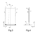
- a modular display shelving according to the present invention is generally indicated by reference number 10.
- the modular display shelving 10 comprises a support element in the form of a panel 11 that extends from a base 12 along a direction V generally perpendicular thereto, hence a substantially vertical direction with reference to an operating configuration of the display shelving.
- the base 12 is for example provided with a plurality of support feet 120 that are configured so as to allow fine adjustments of the position of the panel 11 with respect to a support surface such as a floor.
- a plurality of parallel grooves 13 are formed in the panel 11, each groove stretching out in a horizontal direction H, perpendicular to the vertical direction V, from one end of the panel 11 to the other ending up in its side edges.
- the modular shelving 10 also comprises a plurality of profiled elements 20 mounted on the panel element 11, every one of which extends in the horizontal direction H along at least a portion of the related groove 13, preferably from one end to the opposite end of the panel 11 along the horizontal direction H.
- the profiled elements 20 are preferably blocked in the respective grooves 13 in the horizontal direction by way of screws or equivalent fastening means.
- the modular shelving 10 also comprises in a known manner a plurality of shelves 30 which are assembled to the panel 11 on the profiled elements 20, as it will be described in greater detail hereinafter.
- each profiled element 20 has an H-shaped cross-section wherein a first head portion 21 has a shape matching the shape of the grooves 13, thus allowing its assembly substantially without play in each groove.
- the profiled element 20 also comprises a second head portion 22 spaced from the first head portion 21 and an intermediate or core portion 23 arranged between them and connected to both of them.
- the H-shaped profiled element 20 is for example an extruded beam made of a plastic material, which, due to manufacturing needs, comprises a plurality of inner cavities formed in both the first and second head portions 21, 22, as well as in the intermediate portion 23. These are not limiting features of the invention.
- the first head portion 21 of a profiled element 20 is fitted in one of the grooves 13 of the panel 11, the intermediate portion 23 protrudes from the latter in a transverse direction T, perpendicular to the vertical and horizontal directions V and H, and the second head portion 22 is arranged parallel to the panel 11. Thanks to this arrangement, the second head portion 22 and the intermediate portion 23 define a channel suitable for the assembly of a shelf 30.
- each shelf 30 is provided with connection means whose shape matches the shape of the channels defined by the profiled element 20.
- the connection means of each shelf 30 comprise a pair of elements 31, 32 having hook-shape in cross-section and configured so as to engage the channels of two profiled elements 20 consecutively arranged in the vertical direction V of the display shelving 10. This configuration allows to mount a shelf 30 onto the panel 11 in a stable and safe manner.
- the hook-shaped elements 31, 32 are restrained to a same panel 33 to which a flat element 34 intended to constitute a supporting surface of the shelf 30 is also restrained.
- the hook-shaped elements 31, 32, the panel 33 and the flat element 34 are shown in Figures 5 and 6 , which will be described in greater detail below.
- the display shelving 10 is configured so as to allow illumination of the shelves 30 mounted thereon.
- the shelving 10 comprises in a known manner a pair of electrical conductors 14, 15 arranged on a rear surface of the panel 11, opposite to the surface on which the grooves 13 for the mounting of the profiled elements 20 are formed.
- the electrical conductors 14, 15 are preferably protected by a suitable cover (not shown) of the shelving, fixed to the rear surface of the panel 11, and stretch out along the latter in the vertical direction V, for example close to its side edges.
- the electrical conductors 14, 15 are respectively connected to the terminals of a transformer 16, which transforms the mains voltage e.g. from 220 V to 24 V.
- the shelving 10 also comprises a plurality of strips 17 made of a conductive material, for example having the form of a slats, arranged in each profiled element 20.
- the configuration of the shelving 10 is such that each profiled element 20 is associated with a single conductive strip 17 and that conductive strips 17 mounted on profiled elements that are arranged consecutively in the vertical direction V of the shelving 10 are alternately connected to the positive terminal or the negative terminal of the transformer 16.
- the conductive strips 17 are arranged in the channels defined by the head portions 22 and the intermediate portions 23, and are preferably fixed to the intermediate portions 23, as shown in the cross section of Figure 5 .
- the conductive strips 17 stretch out along the respective channels at least along a portion of them, and preferably from one end to the opposite end of the panel 11 in the horizontal direction H, thus allowing electrical connection of the shelves 30 in any position along the horizontal direction H.
- the conductive strips 17 are located outside of the panel 11, which allows to access them more easily than in the case of known display shelvings with illuminable shelves, and thus to simplify connection of the electrical terminals of the circuits installed on the shelves 30 in order to power the lamps mounted therein.
- each shelf 30 is provided in a known manner with one or more lamps 40 that may be supplied through an appropriate electric circuit (not shown) mounted in the structure of the shelf 30 and comprising a pair of electrical terminals 41, 42 arranged in correspondence to the connection means 31, 32 allowing to mount the shelf to the panel 11.
- an appropriate electric circuit (not shown) mounted in the structure of the shelf 30 and comprising a pair of electrical terminals 41, 42 arranged in correspondence to the connection means 31, 32 allowing to mount the shelf to the panel 11.
- the electrical terminals 41, 42 of the electric circuit of the lamps 40 are respectively arranged in correspondence with the hook-shaped elements 31, 32 and protrude therefrom outwards so as to allow electrical connection with the conductive strips 17 accommodated in the profiled elements 20.
- each electrical terminal 41, 42 includes biasing means, for example in the form of a spring 43, 44, configured so as to urge contact elements of the terminals 41, 42 outwards and compensate for any alignment and contact problem with the conductive strips 17, e.g. due to machining tolerances.
- biasing means for example in the form of a spring 43, 44, configured so as to urge contact elements of the terminals 41, 42 outwards and compensate for any alignment and contact problem with the conductive strips 17, e.g. due to machining tolerances.
- the hook-shaped elements 31, 32 respectively engage the channels defined by two profiled elements 20 arranged consecutively in the vertical direction V and the electrical terminals 41, 42 contact the conductive strips 17, thus closing the electric circuit of the lamps 40 pressed by respective springs 43, 44.
- the lamps 40 used for the illumination of the shelves 30 are of a non-polar type, such as neon lamps, incandescent lamps or non-polarized LEDs, thus not restraining the position of the shelves 30 to the alternate arrangement of the conductive strips 17 connected to either the positive terminal or to negative terminal of the transformer 16.
- the flat elements 34 of the shelves 30 are preferably made of a transparent material and, as shown in Figure 5 , the lamps 40 are for example arranged along an edge thereof extending in the horizontal direction H, thus allowing to exploit the flat elements 34 as light-guides.
- the lamps 40 of each shelf 30 are e.g. arranged in a cavity formed in the panel 33 to which the flat element 34 is fixed.
- the faces of the flat elements 34 of the shelves 30 may be advantageously machined so as to create particular diffusion effects of the light, for example satin or buffed, or machined in order to obtain reflective surfaces suitable to direct light rays emitted by the lamps 40 e.g. upwards or downwards in the vertical direction V so as to illuminate the items arranged on the shelves more effectively.
- the conductive strips may be slats suitable to be fitted into the channels defined by the second head portion 22 and the intermediate portion 23 of the profiled elements 20.
- this is not their only possible configuration.
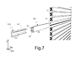
- the conductive strips may be shaped as profiled elements configured so as to engage not only the channels defined by the second head portion 22 and the intermediate portion 23 of each profiled element 20, but also the first head portion 21.
- the conductive strip 170 comprises a first portion 171 configured to be fitted in the channel defined by the second head portion 22 and the intermediate portion 23 of a profiled element 20, as well as a second portion 172, contiguous to the first portion 171, whose shape matches the shape of the first head portion 21 of the profiled element 20.
- This configuration provides a more stable anchoring of the conductive strips 170 to the respective profiled elements 20 of the modular shelving 10, because they are substantially wound around the second portion 172 on the profiled elements 20 at the portion intended to be fixed into the panel 11.
- This configuration also simplifies electric connection of the conductive strips, which can be achieved by using the screws 140, 150 employed to connect the electrical conductors 14, 15 to the rear surface of the panel 11 of the shelving 10. As shown in Figures 5 and 8 , these screws also serve to mechanically block the profiled elements 20 inside the grooves 13 of the panel 11 along the horizontal direction H.
- the surface of the head 22 of the profiled elements 20 projecting from the panel 11 may be advantageously used for the application of decorative elements so as to create surface finishing effects allowing to customize the design of the display shelving in an extremely simple and cheap manner depending on the needs of the end user.
- Profiled elements 20 made of plastic materials may for example be co-molded with decorative elements by way of the widely known and diffused in-mold decoration techniques, also known under the acronym IMD.
Landscapes
- Devices For Medical Bathing And Washing (AREA)
- Finger-Pressure Massage (AREA)
- Measurement And Recording Of Electrical Phenomena And Electrical Characteristics Of The Living Body (AREA)
- Devices For Indicating Variable Information By Combining Individual Elements (AREA)
Applications Claiming Priority (1)
| Application Number | Priority Date | Filing Date | Title |
|---|---|---|---|
| ITMI2014U000044U ITMI20140044U1 (it) | 2014-02-04 | 2014-02-04 | Scaffalatura modulare |
Publications (1)
| Publication Number | Publication Date |
|---|---|
| EP2901896A1 true EP2901896A1 (de) | 2015-08-05 |
Family
ID=52807512
Family Applications (1)
| Application Number | Title | Priority Date | Filing Date |
|---|---|---|---|
| EP15153580.4A Withdrawn EP2901896A1 (de) | 2014-02-04 | 2015-02-03 | Modulares Präsentationsregalsystem |
Country Status (2)
| Country | Link |
|---|---|
| EP (1) | EP2901896A1 (de) |
| IT (1) | ITMI20140044U1 (de) |
Cited By (2)
| Publication number | Priority date | Publication date | Assignee | Title |
|---|---|---|---|---|
| EP3231328A1 (de) * | 2016-04-12 | 2017-10-18 | Viabizzuno S.r.L. | Regalsystem |
| CN110854633A (zh) * | 2019-10-22 | 2020-02-28 | 赛尔富电子有限公司 | 一种陈列展示用的供电装置 |
Citations (2)
| Publication number | Priority date | Publication date | Assignee | Title |
|---|---|---|---|---|
| GB2255820A (en) | 1991-05-14 | 1992-11-18 | A M S Retail Interiors Limited | Illuminated display shelving system |
| FR2793667A1 (fr) * | 1999-05-19 | 2000-11-24 | Tipsy Creation | Systeme de presentoir de produits et accessoire pour un tel systeme de presentoir |
-
2014
- 2014-02-04 IT ITMI2014U000044U patent/ITMI20140044U1/it unknown
-
2015
- 2015-02-03 EP EP15153580.4A patent/EP2901896A1/de not_active Withdrawn
Patent Citations (2)
| Publication number | Priority date | Publication date | Assignee | Title |
|---|---|---|---|---|
| GB2255820A (en) | 1991-05-14 | 1992-11-18 | A M S Retail Interiors Limited | Illuminated display shelving system |
| FR2793667A1 (fr) * | 1999-05-19 | 2000-11-24 | Tipsy Creation | Systeme de presentoir de produits et accessoire pour un tel systeme de presentoir |
Cited By (2)
| Publication number | Priority date | Publication date | Assignee | Title |
|---|---|---|---|---|
| EP3231328A1 (de) * | 2016-04-12 | 2017-10-18 | Viabizzuno S.r.L. | Regalsystem |
| CN110854633A (zh) * | 2019-10-22 | 2020-02-28 | 赛尔富电子有限公司 | 一种陈列展示用的供电装置 |
Also Published As
| Publication number | Publication date |
|---|---|
| ITMI20140044U1 (it) | 2015-08-04 |
Similar Documents
| Publication | Publication Date | Title |
|---|---|---|
| US5072343A (en) | Illuminated rack assembly, in particular a display case | |
| US6231205B1 (en) | Illuminated shelving | |
| US9136615B2 (en) | Shelf lighting connector assembly | |
| EP3021037B1 (de) | Lichtstab | |
| US20100135020A1 (en) | Modular illumination systems | |
| US7572034B2 (en) | Multiple side illumination assembly | |
| US10323822B2 (en) | Lighting arrangement, construction kit for a lighting arrangement, and method for constructing a lighting arrangement | |
| JP2012134040A (ja) | 陳列棚の照明器具 | |
| US20050173605A1 (en) | Display shelving device with integrated electrical power supply means for lighting units | |
| US12560291B2 (en) | Profile arrangement for setting up exhibition stands or shop fittings | |
| WO2011119434A2 (en) | Linear configuration lighting module and application thereof | |
| EP2157357B1 (de) | Modulare Boden- oder Wandeinbauleuchte | |
| EP2901896A1 (de) | Modulares Präsentationsregalsystem | |
| US11004366B2 (en) | Illumination display platforms and related methods | |
| CA2554010A1 (en) | Radiance lighting system and method | |
| US9516954B2 (en) | Showcase member with direct-mounted LED light source | |
| WO2019075491A2 (en) | FALSE CEILING LIGHTING DEVICE, FALSE CEILING COMPRISING SUCH A LIGHTING DEVICE AND METHOD FOR MOUNTING SUCH A LIGHTING DEVICE | |
| EP3567571A1 (de) | Blitzstruktur | |
| WO2014118528A1 (en) | Display panel and method of manufacture | |
| US10151466B2 (en) | Laterally supported lights | |
| GB2205226A (en) | Shelf insert | |
| EP3719393A1 (de) | Regal oder elektrifizierte anzeige | |
| US6149281A (en) | Neon lighting fixture | |
| KR0138427Y1 (ko) | 장식용 조명등 | |
| CN121816480A (zh) | 具有主动变形的柔性led灯带 |
Legal Events
| Date | Code | Title | Description |
|---|---|---|---|
| PUAI | Public reference made under article 153(3) epc to a published international application that has entered the european phase |
Free format text: ORIGINAL CODE: 0009012 |
|
| 17P | Request for examination filed |
Effective date: 20150203 |
|
| AK | Designated contracting states |
Kind code of ref document: A1 Designated state(s): AL AT BE BG CH CY CZ DE DK EE ES FI FR GB GR HR HU IE IS IT LI LT LU LV MC MK MT NL NO PL PT RO RS SE SI SK SM TR |
|
| AX | Request for extension of the european patent |
Extension state: BA ME |
|
| STAA | Information on the status of an ep patent application or granted ep patent |
Free format text: STATUS: THE APPLICATION IS DEEMED TO BE WITHDRAWN |
|
| 18D | Application deemed to be withdrawn |
Effective date: 20160206 |