EP2901928B1 - Dispositif de mesure de corps vivant non invasif - Google Patents
Dispositif de mesure de corps vivant non invasif Download PDFInfo
- Publication number
- EP2901928B1 EP2901928B1 EP13840482.7A EP13840482A EP2901928B1 EP 2901928 B1 EP2901928 B1 EP 2901928B1 EP 13840482 A EP13840482 A EP 13840482A EP 2901928 B1 EP2901928 B1 EP 2901928B1
- Authority
- EP
- European Patent Office
- Prior art keywords
- light
- finger
- light emitting
- unit
- light amount
- Prior art date
- Legal status (The legal status is an assumption and is not a legal conclusion. Google has not performed a legal analysis and makes no representation as to the accuracy of the status listed.)
- Active
Links
Images





Classifications
-
- A—HUMAN NECESSITIES
- A61—MEDICAL OR VETERINARY SCIENCE; HYGIENE
- A61B—DIAGNOSIS; SURGERY; IDENTIFICATION
- A61B5/00—Measuring for diagnostic purposes; Identification of persons
- A61B5/145—Measuring characteristics of blood in vivo, e.g. gas concentration or pH-value ; Measuring characteristics of body fluids or tissues, e.g. interstitial fluid or cerebral tissue
- A61B5/1455—Measuring characteristics of blood in vivo, e.g. gas concentration or pH-value ; Measuring characteristics of body fluids or tissues, e.g. interstitial fluid or cerebral tissue using optical sensors, e.g. spectral photometrical oximeters
-
- A—HUMAN NECESSITIES
- A61—MEDICAL OR VETERINARY SCIENCE; HYGIENE
- A61B—DIAGNOSIS; SURGERY; IDENTIFICATION
- A61B5/00—Measuring for diagnostic purposes; Identification of persons
- A61B5/145—Measuring characteristics of blood in vivo, e.g. gas concentration or pH-value ; Measuring characteristics of body fluids or tissues, e.g. interstitial fluid or cerebral tissue
- A61B5/1455—Measuring characteristics of blood in vivo, e.g. gas concentration or pH-value ; Measuring characteristics of body fluids or tissues, e.g. interstitial fluid or cerebral tissue using optical sensors, e.g. spectral photometrical oximeters
- A61B5/14551—Measuring characteristics of blood in vivo, e.g. gas concentration or pH-value ; Measuring characteristics of body fluids or tissues, e.g. interstitial fluid or cerebral tissue using optical sensors, e.g. spectral photometrical oximeters for measuring blood gases
- A61B5/14552—Details of sensors specially adapted therefor
-
- A—HUMAN NECESSITIES
- A61—MEDICAL OR VETERINARY SCIENCE; HYGIENE
- A61B—DIAGNOSIS; SURGERY; IDENTIFICATION
- A61B5/00—Measuring for diagnostic purposes; Identification of persons
- A61B5/145—Measuring characteristics of blood in vivo, e.g. gas concentration or pH-value ; Measuring characteristics of body fluids or tissues, e.g. interstitial fluid or cerebral tissue
- A61B5/14546—Measuring characteristics of blood in vivo, e.g. gas concentration or pH-value ; Measuring characteristics of body fluids or tissues, e.g. interstitial fluid or cerebral tissue for measuring analytes not otherwise provided for, e.g. ions, cytochromes
-
- A—HUMAN NECESSITIES
- A61—MEDICAL OR VETERINARY SCIENCE; HYGIENE
- A61B—DIAGNOSIS; SURGERY; IDENTIFICATION
- A61B5/00—Measuring for diagnostic purposes; Identification of persons
- A61B5/68—Arrangements of detecting, measuring or recording means, e.g. sensors, in relation to patient
- A61B5/6801—Arrangements of detecting, measuring or recording means, e.g. sensors, in relation to patient specially adapted to be attached to or worn on the body surface
- A61B5/6813—Specially adapted to be attached to a specific body part
- A61B5/6825—Hand
- A61B5/6826—Finger
-
- A—HUMAN NECESSITIES
- A61—MEDICAL OR VETERINARY SCIENCE; HYGIENE
- A61B—DIAGNOSIS; SURGERY; IDENTIFICATION
- A61B5/00—Measuring for diagnostic purposes; Identification of persons
- A61B5/68—Arrangements of detecting, measuring or recording means, e.g. sensors, in relation to patient
- A61B5/6801—Arrangements of detecting, measuring or recording means, e.g. sensors, in relation to patient specially adapted to be attached to or worn on the body surface
- A61B5/6844—Monitoring or controlling distance between sensor and tissue
-
- A—HUMAN NECESSITIES
- A61—MEDICAL OR VETERINARY SCIENCE; HYGIENE
- A61B—DIAGNOSIS; SURGERY; IDENTIFICATION
- A61B5/00—Measuring for diagnostic purposes; Identification of persons
- A61B5/70—Means for positioning the patient in relation to the detecting, measuring or recording means
-
- A—HUMAN NECESSITIES
- A61—MEDICAL OR VETERINARY SCIENCE; HYGIENE
- A61B—DIAGNOSIS; SURGERY; IDENTIFICATION
- A61B2560/00—Constructional details of operational features of apparatus; Accessories for medical measuring apparatus
- A61B2560/04—Constructional details of apparatus
- A61B2560/0431—Portable apparatus, e.g. comprising a handle or case
-
- A—HUMAN NECESSITIES
- A61—MEDICAL OR VETERINARY SCIENCE; HYGIENE
- A61B—DIAGNOSIS; SURGERY; IDENTIFICATION
- A61B2562/00—Details of sensors; Constructional details of sensor housings or probes; Accessories for sensors
- A61B2562/02—Details of sensors specially adapted for in-vivo measurements
- A61B2562/0233—Special features of optical sensors or probes classified in A61B5/00
- A61B2562/0238—Optical sensor arrangements for performing transmission measurements on body tissue
-
- A—HUMAN NECESSITIES
- A61—MEDICAL OR VETERINARY SCIENCE; HYGIENE
- A61B—DIAGNOSIS; SURGERY; IDENTIFICATION
- A61B2576/00—Medical imaging apparatus involving image processing or analysis
- A61B2576/02—Medical imaging apparatus involving image processing or analysis specially adapted for a particular organ or body part
-
- G—PHYSICS
- G16—INFORMATION AND COMMUNICATION TECHNOLOGY [ICT] SPECIALLY ADAPTED FOR SPECIFIC APPLICATION FIELDS
- G16H—HEALTHCARE INFORMATICS, i.e. INFORMATION AND COMMUNICATION TECHNOLOGY [ICT] SPECIALLY ADAPTED FOR THE HANDLING OR PROCESSING OF MEDICAL OR HEALTHCARE DATA
- G16H30/00—ICT specially adapted for the handling or processing of medical images
- G16H30/40—ICT specially adapted for the handling or processing of medical images for processing medical images, e.g. editing
Definitions
- the present invention relates to a non-invasive living body measurement device that irradiates a finger of a subject with light and obtains transmitted light, captures an image of the finger by receiving the transmitted light with an imaging unit, and detects biological information regarding the subject by processing the obtained image.
- a non-invasive living body measurement device in which a finger of a subject is irradiated with light, optical information is acquired by receiving transmitted light or reflected light therefrom with a light receiving unit, and biological information regarding the subject is obtained by analyzing the optical information (e.g., Patent Document 1).
- the noninvasive living body measurement apparatus disclosed in Patent Document 1 includes a platform on which the finger of the subject is placed, a cover unit that covers the finger placed on the platform, two light source units attached to the cover unit, and an imaging unit. An image of the subject's finger is captured by an imaging unit receiving transmitted light that passes through the finger when light is emitted from the light source units, thus obtaining a transmission image of the subject's finger, and the hemoglobin concentration of the subject is detected by processing the image.
- US 2009/174766 A1 describes a finger vein authentication unit including a light source which irradiates infrared light to a finger and an imaging sensor which images a vein image by the light which is diffused in the finger and transmitted through the front side of the finger.
- the photographing operation is performed in a state in which the first joint is laid on the central portion of a groove. Since the skin of the first joint is thin, the vein can be photographed using a smaller amount of light compared with other portions. Accordingly, strong light is irradiated to the portions other than the first joint and slightly weak light is irradiated to the first joint. Thus, the amount of light of the whole image becomes uniform.
- US 2002/048014A1 describes a personal identification system which uses a vein pattern of a finger, optimizes the amount of light of a light source based on a captured finger image and emphasizes the vein pattern during image processing for identification.
- the light transmission factor is highest in joints. Therefore, the system detects a joint from the light intensity profile of a finger in the major axis in the image data and uses the maximum intensity value as the intensity value of the joint.
- US 2008/306366A1 describes a biological-information obtaining apparatus including a light-emitting unit configured to emit light, an image-capturing unit configured to capture images, in time sequence, obtained by irradiating a living body with the light emitted and by causing the light to be transmitted through or reflected by the living body.
- the biological-information obtaining apparatus can be used as a vein authentication apparatus. That is, the use of such a vein authentication apparatus can achieve both identifying of an individual on the basis of vein authentication and obtaining of biological information (information regarding health) regarding the individual.
- JP 2008-067727 describes a personal identification device comprising a plurality of light emitting units arranged in a line along a lengthwise direction of a finger, wherein the light emitting units are each equipped with a plurality of light emitting devices configured to emit light of mutually different wavelengths. A difference between finger vein images of different wavelengths is determined to judge whether the finger is a finger of a living body or a forged finger.
- Patent Document 1 JP 2000-262496A
- the present invention has been achieved in light of this situation, and an object thereof is to provide a non-invasive living body measurement device that can obtain a clear image of a finger of a subject, and whose precision in biological information detection is improved over conventional technology.
- a non-invasive living body measurement device includes: a platform for placement of a finger of a subject that is a measurement target; a plurality of light emitting units arranged in a line along a lengthwise direction of the finger placed on the platform; a light amount adjustment unit that adjusts a light amount of each of the plurality of light emitting units; an imaging unit that obtains an image of the finger placed on the platform by receiving transmitted light that passed through the finger when light was emitted from the light emitting units; and an information processing unit that detects biological information regarding the subject by processing the image obtained by the imaging unit.
- the transmitted light amount is made uniform with respect to the lengthwise direction of the finger, thus preventing the image of the subject's finger from having locally dark and light portions, and obtaining a clear image.
- the region of interest that is to be the image processing target is larger, thus making it possible to set a more appropriate region of interest than in conventional technology.
- the light amount adjustment unit may be configured to set the light amount of a light emitting unit provided at a position closest to a joint of the finger placed on the platform lower than the light amount of another light emitting unit. Since light easily passes through the joint portion, by setting the light amount of the light emitting unit corresponding to this portion lower than the light amounts of the other light emitting units, it is possible to prevent the image of the subject's finger from having locally dark and light portions.
- the light amount adjustment unit may be configured to increase the light amount of each of the light emitting units with increasing distance from the joint of the finger placed on the platform. Light passes less readily with increasing distance from the joint portion of the finger, and therefore according to the above configuration, it is possible to prevent the image of the subject's finger from having locally dark and light portions.
- the light amount adjustment unit may be configured to adjust the light amounts of the light emitting units such that the light amount increases non-linearly with increasing distance from the joint of the finger placed on the platform.
- the transmittance of light changes non-linearly with increasing distance from the joint portion of the finger, and therefore according to the above configuration, the transmitted light amount is made even more uniform with respect to the lengthwise direction of the finger.
- the light amount adjustment unit may be configured to determine extents of change in the light amounts of the light emitting units relative to distance from the joint of the finger placed on the platform, and adjust the light amounts of the light emitting units in accordance with the determined extents of change in the light amounts.
- the light amount adjustment unit may be configured to adjust the light amounts of the light emitting units such that an average value of light amounts of transmitted light that passed through the finger placed on the platform is a predetermined value.
- the light amount adjustment unit may be configured to adjust the light amounts of the light emitting units based on a transmission image of the finger obtained by the imaging unit.
- the light amount adjustment unit may be configured to adjust the light amounts of the light emitting units based on luminance in the transmission image of the finger obtained by the imaging unit.
- the information processing unit may be configured to control the light amount adjustment unit so as to execute light amount adjustment processing on the light emitting units before image processing is performed on the finger of the subject by the imaging unit.
- the light emitting units are each equipped with a plurality of light emitting devices that emit light of mutually different wavelengths, and light emitting devices that emit light of the same wavelength may be arranged in a line along the lengthwise direction of the finger placed on the platform.
- the present invention it is possible to obtain a clear image of a finger of a subject, and possible to improve precision in biological information detection.
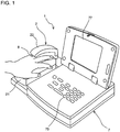
- FIG. 1 is a perspective view of the external configuration of a non-invasive living body measurement device 1 according to the present embodiment.
- the non-invasive living body measurement device 1 includes a measurement unit 2 and an information processing unit 7.
- the measurement unit 2 is for capturing images of a subject's finger
- the information processing unit 7 is for detecting biological information (hemoglobin value, venous oxygenation index) regarding the subject by processing the imaging data (image data) from the measurement unit 2, and displaying the biological information as the detection result.
- biological information hemoglobin value, venous oxygenation index
- the measurement unit 2 includes a platform 21 on which a finger 8 of the subject can be placed, and a cover unit 22 for covering the finger 8 placed on the platform 21.
- the cover unit 22 is arranged above the platform 21, and is pivotably attached to the platform 21.
- the cover unit 22 can open and close (cover the finger 8 and expose the finger 8) by swinging relative to the platform 21.
- FIG. 2 is a block diagram showing the configuration of the non-invasive living body measurement device 1.
- the measurement unit 2 has a light emitting apparatus 3, an imaging unit 4 constituted by a CCD, a light amount adjustment unit 5 that adjusts the light emission amount of the light emitting apparatus 3, and a communication interface 6.
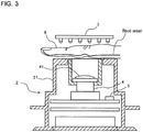
- FIG. 3 is a cross-sectional side view of the configuration of the measurement unit 2.
- the light emitting apparatus 3 is equipped with multiple LEDs, and is arranged on the cover unit 22.
- a base is provided within the platform 21, and the imaging unit 4, the light amount adjustment unit 5, and the communication interface 6 are attached to the base.
- the imaging unit 4 is provided on the base such that the light receiving face is facing upward, and a lens system 41 is arranged above the imaging unit 4. Also, in this configuration, the light emitting apparatus 3 is located above the imaging unit 4 when the cover unit 22 is closed.
- the subject's finger 8 can be placed on the platform 21 as described above. At this time, the subject's middle finger 8 is placed so as to be located directly above the imaging unit 4. Also, the platform 21 is formed so as to conform to the shape of the subject's middle finger 8, and is configured such that the second joint of the subject's middle finger 8 is located at the center of the imaging range of the imaging unit 4 when the subject's hand is placed over the platform 21.
- the light emitting apparatus 3 and the imaging unit 4 oppose each other so as to sandwich the subject's finger 8 from above and below.
- the light emitting apparatus 3 is configured so as to emit light downward, and the light emitted from the light emitting apparatus 3 passes through the subject's finger 8. This transmitted light passes through the lens system 41 and arrives at the imaging unit 4. In this way, a transmission image of the subject's finger 8 is obtained by the imaging unit 4.
- the light amount adjustment unit 5 is constituted by an FPGA (Field-Programmable Gate Array). This light amount adjustment unit 5 receives an output signal from the imaging unit 4 and performs light amount adjustment on the light emitting apparatus 3 based on the output signal. The light amount adjustment performed on the light emitting apparatus 3 will be described in detail later.
- FPGA Field-Programmable Gate Array
- the communication interface 6 is communicably connected to the imaging unit 4 and the light amount adjustment unit 5.
- This communication interface 6 is constituted by a USB interface, for example, and is connected to the information processing unit 7 via a communication cable.
- the measurement unit 2 can exchange data with the information processing unit 7 using the communication interface 6.
- the information processing unit 7 has a CPU 71, a ROM 72, a RAM 73, an external storage apparatus 74, an input unit 75, a communication interface 76, and a display unit 77.
- the CPU 71 executes computer programs stored in the ROM 72 and computer programs loaded to the RAM 73.
- the RAM 73 is used for the reading out of computer programs stored in the ROM 72 and the external storage apparatus 74.
- the RAM 73 is also used as a work area for the CPU 71 when these computer programs are executed.
- the external storage apparatus 74 is constituted by a non-volatile storage device such as a hard disk or a flash memory.
- Various computer programs to be executed by the CPU 71 such as an operating system and application programs, are installed in the external storage apparatus 74 along with data to be used in the execution of the computer programs.
- the input unit 75 is an operation unit provided with multiple keys as shown in FIG. 1 . By operating the keys of this input unit, a user can input various instructions, data, and the like to the non-invasive living body inspection device 1.
- the display unit 77 receives an image signal from the CPU 71, and displays images based on the input images signal.
- the communication interface 76 is a USB interface, and is connected to the communication interface 6 of the measurement unit 2 via a signal cable.
- the information processing unit 7 can exchange data with the measurement unit 2 using the communication interface 76.
- FIG. 4 is a bottom view of the configuration of the light emitting apparatus 3.
- the bottom surface of the light emitting apparatus 3 is shaped as a rectangle that is elongated in one direction.
- This light emitting apparatus 3 is provided with six LED blocks 311 to 316.
- the LED blocks 311 to 316 are arranged in a column along the lengthwise direction of the rectangular shape. This lengthwise direction matches the direction orthogonal to the shaft length direction of the rotation shaft for pivotably attaching the platform 21 and the cover unit 22, that is to say, matches the lengthwise direction of the subject's finger 8 to be placed on the platform 21.
- the LED blocks 311 to 316 are arranged in a column in the lengthwise direction of the rectangular shape. Note that when the cover unit 22 is closed, the center of the light emitting apparatus 3 is located at the center of the imaging range of the imaging unit 4. In other words, in this configuration, when the subject's hand is placed on the platform 21, the second joint of the subject's middle finger 8 is located at the center of the light emitting apparatus 3.
- the LED blocks 311 to 316 respectively include three LEDs, namely LED 311A, LED 311B, and LED 311C to LED 316A, LED 316B, and LED 316C.
- the three LEDs included in the respective LED blocks 311 to 316 namely LED 311A, LED 311B, and LED 311C to LED 316A, LED 316B, and LED 316C, are arranged in a line along the short-side direction of the previously-described rectangular shape of the light emitting apparatus 3. In other words, 18 LEDs are arranged in a matrix in the light emitting apparatus 3.
- the LEDs 311A, 312A, 313A, 314A, 315A, and 316A are configured so as to emit light with a wavelength of 660 nm. This light with a wavelength of 660 nm is absorbed to a greater extent by reduced hemoglobin than oxygenated hemoglobin.
- the LEDs 311B, 312B, 313B, 314B, 315B, and 316B are configured so as to emit light with a wavelength of 805 nm. This light with a wavelength of 805 nm is absorbed to the same extent by oxygenated hemoglobin and reduced hemoglobin.
- the LEDs 311C, 312C, 313C, 314C, 315C, and 316C are configured so as to emit light with a wavelength of 880 nm.
- the LEDs 311A, 312A, 313A, 314A, 315A, and 316A that emit light with a wavelength of 660 nm and the LEDs 311B, 312B, 313B, 314B, 315B, and 316B that emit light with a wavelength of 805 nm are used to measure a venous oxygenation index.
- the LEDs 311B, 312B, 313B, 314B, 315B, and 316B that emit light with a wavelength of 805 nm and the LEDs 311C, 312C, 313C, 314C, 315C, and 316C that emit light with a wavelength of 880 nm are used to measure a hemoglobin concentration.
- the LEDs 311A, 312A, 313A, 314A, 315A, and 316A that emit light with a wavelength of 660 nm are arranged in a column along the lengthwise direction of the light emitting apparatus 3.
- the LEDs 311B, 312B, 313B, 314B, 315B, and 316B that emit light with a wavelength of 805 nm are also arranged in a column along the lengthwise direction of the light emitting apparatus 3
- the LEDs 311C, 312C, 313C, 314C, 315C, and 316C that emit light with a wavelength of 880 nm are also arranged in a column along the lengthwise direction of the light emitting apparatus 3.
- FIG. 5 is a circuit diagram of the configuration of the light emitting apparatus 3.
- the light emitting apparatus 3 is equipped with a drive unit 32 for driving the LEDs 311A to 316A, 311B to 316B, and 311C to 316C.
- the drive unit 32 is provided with drive circuits 321 to 326 for respectively driving the LED blocks 311 to 316.
- the LED blocks 311 to 316 are individually driven by the drive circuits 321 to 326.
- the drive unit 32 is provided with a constant current power supply unit 33.
- a power supply unit 23 provided in the platform 21 is connected to the constant current power supply unit 33, and constant current is supplied from the constant current power supply unit 33 to the drive circuits 321 to 326.
- the power supply unit 23 is connected to each of three LED wavelength control units 341, 342, and 343 provided in the light emitting apparatus 3.
- the LED wavelength control unit 341 is connected to the LEDs 311A, 312A, 313A, 314A, 315A, and 316A that emit light with a wavelength of 660 nm, and performs control such that the emitted light wavelength of these LEDs 311A, 312A, 313A, 314A, 315A, and 316A is 660 nm.
- the LED wavelength control unit 342 is connected to the LEDs 311B, 312B, 313B, 314B, 315B, and 316B that emit light with a wavelength of 805 nm, and performs control such that the emitted light wavelength of these LEDs 311B, 312B, 313B, 314B, 315B, and 316B is 805 nm.
- the LED wavelength control unit 343 is connected to the LEDs 311C, 312C, 313C, 314C, 315C, and 316C that emit light with a wavelength of 880 nm, and performs control such that the emitted light wavelength of these LEDs 311C, 312C, 313C, 314C, 315C, and 316C is 880 nm.
- the light amount adjustment unit 5 is connected to each of the drive circuits 321 to 326. This light amount adjustment unit 5 outputs a PWM signal to each of the drive circuits 321 to 326.
- the drive circuits 321 to 326 each supply a current that corresponds to the duty ratio of the received PWM (Pulse Width Modulation) signal to the corresponding one of the LED blocks 311 to 316.
- the light emission amounts of the LED blocks 311 to 316 are thus adjusted individually. In this case, current with the same value is supplied to each of the three LEDs provided in the same LED block. In other words, the three LEDs in the same LED block are subjected to light amount adjustment in an integrated manner.
- FIG. 6 is a flowchart showing a procedure of operation of the non-invasive living body measurement device 1 according to the present embodiment.
- a subject is to use the non-invasive living body measurement device 1
- the subject's middle finger 8 is placed on the platform 21.
- the second joint of the subject's middle finger 8 is located at the central position in the imaging range of the imaging unit 4.
- the subject inputs a measurement start instruction to the non-invasive living body measurement device 1 by operating the input unit 75 of the information processing unit 7.
- the CPU 71 of the information processing unit 7 transmits data for instructing execution of light amount adjustment processing on the light emitting apparatus 3 to the measurement unit 2 (step S101).
- the light amount adjustment unit 5 of the measurement unit 2 receives the execution instruction data and executes light amount adjustment processing.
- FIG. 7 is a flowchart showing a procedure of light amount adjustment processing.
- the light amount adjustment unit 5 sets initial values for the values of current to be supplied to (light amounts of) the LED blocks 311 to 316 (step S201). According to these initial values, the values of current to be supplied to the LED blocks 311 to 316 are set such that among the LED blocks 311 to 316, the light amount is the smallest for the LED blocks 313 and 314 that are the closest to the second joint of the subject's middle finger 8, and the light amount increases with increasing distance from the LED blocks 313 and 314.
- a transmission image of the subject's middle finger 8 is obtained by the imaging unit 4 in this state, and the transmission image is given to the light amount adjustment unit 5.
- the transmission image contains a transmission image whose range is from the vicinity of the first joint of the subject's middle finger 8 to the third joint (base).
- the transmission image is a 256-level monochrome image.
- the light amount adjustment unit 5 obtains an average luminance for all of the pixels in the transmission image, and determines whether the average luminance falls within a predetermined intermediate range centered on 127, which is the median value of the 256 levels (step S202).
- the light amount adjustment unit 5 increases or decreases the values of current to be supplied to (light amounts of) the LED blocks 311 to 316 (step S203). Specifically, if the average luminance is lower than the intermediate range, the light amounts of the LED blocks 311 to 316 are increased, and if the average luminance is higher than the intermediate range, the light amounts of the LED blocks 311 to 316 are decreased.
- step S203 the values of current to be supplied to the LED blocks 311 to 316 are adjusted by changing the parameter C in the equation 1 above. In other words, the overall light amount of the LED blocks 311 to 316 is increased or decreased while maintaining the light amount differences between the LED blocks 311 to 316.
- step S203 After the processing of step S203 is performed, the light amount adjustment unit 5 returns to the processing of step S202. Accordingly, the processing of steps S202 and S203 is repeated until the average luminance falls within the intermediate range.
- the light amount adjustment unit 5 obtains an average luminance for each of a predetermined number of (two or more) columns of pixels aligned in the direction orthogonal to the lengthwise direction of the subject's middle finger 8 in the transmission image, and determines whether each of the average luminances falls within the intermediate range (step S204).
- the light amount adjustment unit 5 obtains an average luminance for each of the columns of pixels aligned in the direction orthogonal to the lengthwise direction of the subject's middle finger 8, and calculates the difference between the maximum value and the minimum value among the average luminances (step S205).
- the light amount adjustment unit 5 increases or decreases the values of current to be supplied to the LED blocks 311 to 316 in accordance with the calculated difference between the maximum value and minimum value among the average luminances (step S206).
- FIG. 9 is a graph for describing light amount adjustment performed on the light emitting apparatus 3 in step S206. In FIG.
- the vertical axis y indicates the current value
- the horizontal axis x indicates the LED block position.
- the values of current to be supplied to the LED blocks 311 to 316 are given by the following quadratic equation 2.
- the values of current to be supplied to the LED blocks 311 to 316 are adjusted by changing the parameter P in the equation 2 above. Specifically, as shown in FIG. 9 , if the difference between the maximum value and minimum value among the average luminances is larger than a predetermined value, the parameter P is adjusted such that the curvature of the parabola decreases, and if the difference between the maximum value and minimum value among the average luminances is smaller than the predetermined value, the parameter P is adjusted such that the curvature of the parabola increases.
- step S206 After the processing of step S206 is performed, the light amount adjustment unit 5 returns to the processing of step S204. Accordingly, the processing of steps S204 to S206 is repeated until the average luminances fall within the intermediate range.
- the light amount adjustment unit 5 transmits data notifying the end of light amount adjustment processing to the information processing unit 7 (step S207), and ends the light amount adjustment processing.
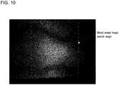
- FIG. 10 is a diagram showing an example of a transmission image of a finger obtained by a conventional illumination method
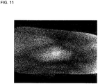
- FIG. 11 is a diagram showing an example of a transmission image of a finger after execution of light amount adjustment processing by the non-invasive living body measurement device 1 according to the present embodiment. It can be seen that light more easily passes through the joint portion of the finger than the other portions. As shown in FIG. 10 , with a conventional illumination method, the light amounts of all of the light emitting devices are set the same, and therefore the joint portion of the finger is much brighter than the other portions.
- blood vessel image an image of a blood vessel portion (hereinafter, referred to as "blood vessel image”) in the transmission image and set the blood vessel image as the processing target.
- the transmission image obtained by a conventional illumination method it is necessary to find a blood vessel image in the portion of the transmission image corresponding to the joint portion of the finger.
- the region in which the blood vessel image can be found is limited to the joint portion of the finger, and there is a risk of not being able to find an appropriate blood vessel image.
- the transmission image of the finger after execution of light amount adjustment processing in the present embodiment the obtained image is an overall clear image that does not have locally dark and light portions. For this reason, the search range for the blood vessel image is larger than in conventional technology, and an appropriate blood vessel image is easier to find.
- step S102 if the information processing unit 7 receives light amount adjustment processing end notification data (step S102), the CPU 71 executes hemoglobin concentration detection processing as will be described below (step S103).
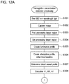
- FIGS. 12A and 12B are flowchart showing a procedure of hemoglobin concentration detection processing.
- the CPU 71 causes the LEDs 311C, 312C, 313C, 314C, 315C, and 316C to irradiate the subject's finger 8 with light with a wavelength of 880 nm (step S301), and causes the imaging unit 4 to capture an image of the finger 8 (step S302).
- the CPU 71 searches for the blood vessel image region having the highest contrast in the transmission image for 880 nm wavelength light captured by the imaging unit 4 (hereinafter, referred to as "first transmission image”) (step S303), and sets the found region as the processing target region (step S304).
- the CPU 71 performs logarithmic transformation on a luminance distribution whose range crosses a blood vessel in the processing target region, and, based on the transformed image luminance distribution, creates a valley-shaped luminance profile whose local minimum is at the center of the blood vessel (step S305).
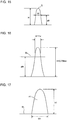
- FIG. 13 is a graph showing an example of a luminance profile. In FIG. 13 , the vertical axis indicates logarithmic luminance, and the horizontal axis indicates distance. Subsequently, the CPU 71 performs absorption profile creation and baseline determination based on the obtained luminance profile (step S306).
- FIG. 14 is a flowchart showing a procedure of absorption profile creation and baseline determination processing.
- the CPU 71 sets a constant a (e.g., 0.7) (step S401).
- the CPU 71 sets H to a predetermined minimum value (e.g., 10% of a maximum depth Hm in the luminance profile) (step S402).
- the CPU 71 then clips out the portion from a valley bottom P to the depth H from the luminance profile (step S403), and converts the clipped-out portion into an absorption profile (step S404).
- FIG. 15 is a graph showing an example of an absorption profile.
- the CPU 71 considers the absorption profile to be a distribution function (probability density function), and calculates a standard deviation ⁇ thereof and a width W at a height aH in the absorption profile (step S405).
- step S406 determines whether 2 ⁇ and W match (step S406), and if they do not match (NO in step S406), re-sets H to a slightly higher value (step S407), and then returns to the processing of step S403.
- the CPU 71 clips out the portion above the baseline BL in the absorption profile in FIG. 16 , as shown in FIG. 17 , and determines the clipped-out portion as the blood vessel profile (step S307).
- a height h1, a width W1, and an area A1 of the blood vessel profile shown in FIG. 17 are then calculated (step S308).
- the CPU 71 causes the LEDs 311B, 312B, 313B, 314B, 315B, and 316B to irradiate the subject's finger 8 with light with a wavelength of 805 nm (step S309), and causes the imaging unit 4 to capture an image of the finger 8 (step S310).
- the CPU 71 searches for the same region as in step S304 in the transmission image for 805 nm wavelength light (hereinafter, referred to as "second transmission image") captured by the imaging unit 4, and sets the found region as the processing target region (step S311).
- steps S312 to S315 processing similar to the processing performed on the first transmission image in steps S305 to S308 is performed on the second transmission image, and a height h2, a width W2, and an area A2 are calculated for the blood vessel profile corresponding to the wavelength of 805 nm.
- the CPU 71 calculates a depth t from the tissue surface to the blood vessel using the following equation (step S316).
- t h 2 / W 2 n / h 1 / W 1 m Note that m and n are constants.
- the CPU 71 calculates a blood vessel diameter ⁇ as well as a hemoglobin concentration Hgb and a hematocrit value Hct of the blood flowing through the blood vessel using equations 4 to 6 respectively (step S317).
- Hgb h 1 / A 1 q ⁇ f 2 t ⁇ g ⁇
- p and q are constants
- the functions f1, f2, and g are functions determined experimentally.
- Hct k ⁇ h 1 / h 2 + L Note that k and L are constants.
- the CPU 71 After the blood vessel depth, blood vessel diameter, hemoglobin concentration, and hematocrit value are obtained as described above, the CPU 71 returns to the call address of hemoglobin concentration detection processing in the main routine.
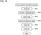
- FIG. 18 is a flowchart showing a procedure of venous oxygenation index detection processing.
- the CPU 71 extracts an absorbance Ab2 for 805 nm wavelength light from the second transmission image acquired in hemoglobin concentration detection processing (step S501).
- the CPU 71 causes the LEDs 311A, 312A, 313A, 314A, 315A, and 316A to irradiate the subject's finger 8 with light with a wavelength of 660 nm (step S502), and causes the imaging unit 4 to capture an image of the finger 8 (step S503).
- the CPU 71 acquires a transmission image for 660 nm wavelength light (hereinafter, referred to as "third transmission image") captured by the imaging unit 4 (step S504), and extracts an absorbance Ab3 for 660 nm wavelength light from the acquired third transmission image (step S505).
- the CPU 71 then calculates a venous oxygenation index VOI using the following equation 7 (step S506).
- VOI ⁇ Ab 3 / Ab 2
- the CPU 71 After the venous oxygenation index is obtained as described above, the CPU 71 returns to the call address of venous oxygenation index detection processing in the main routine.
- venous oxygenation index detection processing ends, as shown in FIG. 6 , the hemoglobin concentration, hematocrit value, and venous oxygenation index obtained by the CPU 71 are displayed on the display unit 77 (step S105), and then this processing ends.
- the above embodiment describes a configuration in which the light amounts of the LED blocks 311 to 316 provided in the light emitting apparatus 3 are independently controlled by the light amount adjustment unit 5, there is no limitation to this.
- a configuration is possible in which the light amounts of all of the LED blocks 311 to 316 are increased or decreased in an integrated manner.
- the LED blocks 311 to 316 are set such that the light amount increases with increasing distance from the LED blocks 313 and 314 that are the closest to the joint of the subject's finger, and the overall light amount of the LED blocks 311 to 316 is increased or decreased while maintaining the light amount differences between the LED blocks 311 to 316.
- the above embodiment describes a configuration in which the light amounts of the LED blocks 311 to 316 are adjusted such that the light amount increases non-linearly with increasing distance from the joint of the finger placed on the platform 21, there is no limitation to this.
- a configuration is possible in which the light amounts of the LED blocks 311 to 316 are adjusted such that the light amount increases linearly with increasing distance from the joint of the finger placed on the platform 21.
- the above embodiment describes a configuration in which the light amounts of the LED blocks 311 to 316 are adjusted such that the light amount increases with increasing distance from the joint of the finger placed on the platform 21, there is no limitation to this.
- the light amounts of the LED blocks 311, 312, 315, and 316 are determined such that the light amounts of the central LED blocks 313 and 314 are low, and the light amount increases with increasing distance from the center, and it is sufficient that the light amounts of the LED blocks are adjusted such that the transmitted light amount is uniform in the imaging range.
- the above embodiment describes a configuration in which the light amount adjustment unit 5 that performs light amount adjustment and the CPU 71 of the information processing unit 7 that performs image processing are provided separately, there is no limitation to this. A configuration is possible in which light amount adjustment processing and image processing are executed by one arithmetic processing unit.
- the above embodiment describes a configuration provided with the LED blocks 311 to 316 arranged in a column, there is no limitation to this, and a configuration is possible in which the LED blocks are arranged in a zigzag line, for example.
- the above embodiment describes a configuration in which a finger of the subject is the imaging target, there is no limitation to this.
- a configuration is possible in which a toe of the subject is imaged, and the hemoglobin concentration of the subject is detected based on the thus-obtained image.
- a non-invasive living body measurement device is useful as a non-invasive living body measurement device that irradiates a finger of a subject with light and obtains transmitted light, captures an image of the finger by receiving the transmitted light with an imaging unit, and detects biological information regarding the subject by processing the obtained image.
Landscapes
- Health & Medical Sciences (AREA)
- Life Sciences & Earth Sciences (AREA)
- Physics & Mathematics (AREA)
- Medical Informatics (AREA)
- Surgery (AREA)
- Engineering & Computer Science (AREA)
- Biomedical Technology (AREA)
- Heart & Thoracic Surgery (AREA)
- Biophysics (AREA)
- Molecular Biology (AREA)
- Pathology (AREA)
- Animal Behavior & Ethology (AREA)
- General Health & Medical Sciences (AREA)
- Public Health (AREA)
- Veterinary Medicine (AREA)
- Optics & Photonics (AREA)
- Spectroscopy & Molecular Physics (AREA)
- Measurement Of The Respiration, Hearing Ability, Form, And Blood Characteristics Of Living Organisms (AREA)
- Image Input (AREA)
Claims (8)
- Dispositif non invasif de mesure d'organisme vivant (1) comprenant :une plate-forme (21) pour placer un doigt (8) d'un sujet qui est une cible de mesure ;une pluralité d'unités d'émission de lumière (311-316) disposées en ligne le long d'une direction longitudinale du doigt placé sur la plate-forme ;une unité de réglage de quantité de lumière (5) configurée pour ajuster une quantité de lumière de chacune de la pluralité d'unités d'émission de lumière ;une unité d'imagerie (4) configurée pour obtenir une image du doigt placé sur la plate-forme en recevant une lumière transmise qui est passée à travers le doigt lorsque de la lumière est émise par les unités d'émission de lumière ; etune unité de traitement d'informations (7) configurée pour détecter des informations biologiques concernant le sujet en traitant l'image obtenue par l'unité d'imagerie, dans lequell'information biologique est une valeur d'hémoglobine ou un indice d'oxygénation veineuse, etles unités d'émission de lumière (311-316) sont chacune équipées avec une pluralité de dispositifs émetteurs de lumière (311A, 311B, 311C ; ... ; 316A, 316B, 316C) configurés pour émettre une lumière de longueurs d'onde mutuellement différentes.
- Dispositif non invasif de mesure d'organisme vivant (1) selon la revendication 1, dans lequel l'unité de réglage de quantité de lumière (5) est configurée pour augmenter la quantité de lumière de chacune des unités d'émission de lumière avec une distance croissante à partir de l'articulation du doigt placé sur la plate-forme.
- Dispositif non invasif de mesure d'organisme vivant (1) selon la revendication 2, dans lequel l'unité de réglage de quantité de lumière (5) est configurée pour ajuster les quantités de lumière des unités d'émission de lumière de telle sorte que la quantité de lumière augmente de manière non linéaire avec une distance croissante à partir de l'articulation du doigt placé sur la plateforme.
- Dispositif non invasif de mesure d'organisme vivant (1) selon la revendication 2 ou 3, dans lequel l'unité de réglage de quantité de lumière (5) est configurée pour déterminer des ampleurs de variation de la quantité de lumière des unités d'émission de lumière par rapport à la distance à partir de l'articulation du doigt placé sur la plate-forme, et ajuster les quantités de lumière des unités d'émission de lumière en fonction des ampleurs de variation déterminées des quantités de lumière.
- Dispositif non invasif de mesure d'organisme vivant (1) selon l'une quelconque des revendications 1 à 4, dans lequel l'unité de réglage de quantité de lumière (5) est configurée pour ajuster les quantités de lumière des unités d'émission de lumière de sorte qu'une valeur moyenne de quantités de lumière de lumière transmise qui passe au travers du doigt placé sur la plate-forme est une valeur prédéterminée.
- Dispositif non invasif de mesure d'organisme vivant (1) selon l'une quelconque des revendications 1 à 5, dans lequel l'unité de réglage de quantité de lumière (5) est configurée pour ajuster les quantités de lumière des unités d'émission de lumière sur la base d'une image de transmission du doigt obtenue par l'unité d'imagerie.
- Dispositif non invasif de mesure d'organisme vivant (1) selon la revendication 6, dans lequel l'unité de réglage de quantité de lumière (5) est configurée pour ajuster les quantités de lumière des unités d'émission de lumière sur la base de la luminance de l'image de transmission du doigt obtenue par l'unité d'imagerie.
- Dispositif non invasif de mesure d'organisme vivant (1) selon l'une quelconque des revendications 1 à 7, dans lequel l'unité de traitement d'informations (5) est configurée pour commander l'unité d'ajustement de lumière pour exécuter un traitement d'ajustement de lumière sur les unités d'émission de lumière avant le traitement d'image sur le doigt du sujet par l'unité d'imagerie.
Applications Claiming Priority (2)
| Application Number | Priority Date | Filing Date | Title |
|---|---|---|---|
| JP2012217216 | 2012-09-28 | ||
| PCT/JP2013/076013 WO2014050945A1 (fr) | 2012-09-28 | 2013-09-26 | Dispositif de mesure de corps vivant non invasif |
Publications (3)
| Publication Number | Publication Date |
|---|---|
| EP2901928A1 EP2901928A1 (fr) | 2015-08-05 |
| EP2901928A4 EP2901928A4 (fr) | 2016-06-01 |
| EP2901928B1 true EP2901928B1 (fr) | 2018-01-31 |
Family
ID=50388340
Family Applications (1)
| Application Number | Title | Priority Date | Filing Date |
|---|---|---|---|
| EP13840482.7A Active EP2901928B1 (fr) | 2012-09-28 | 2013-09-26 | Dispositif de mesure de corps vivant non invasif |
Country Status (5)
| Country | Link |
|---|---|
| US (1) | US20150196240A1 (fr) |
| EP (1) | EP2901928B1 (fr) |
| JP (1) | JP6152111B2 (fr) |
| CN (1) | CN104661595B (fr) |
| WO (1) | WO2014050945A1 (fr) |
Families Citing this family (3)
| Publication number | Priority date | Publication date | Assignee | Title |
|---|---|---|---|---|
| US10521429B2 (en) * | 2015-06-09 | 2019-12-31 | Microsoft Technology Licensing, Llc. | Interactive graphical system for estimating body measurements |
| JP7057277B2 (ja) | 2015-10-08 | 2022-04-19 | ブライトシード・エルエルシー | 脈管サイズを決定するシステム及びその方法 |
| RU2645943C1 (ru) * | 2016-10-04 | 2018-02-28 | Общество с ограниченной ответственностью "ТЕЛЕБИОМЕТ" | Способ неинвазивного определения концентраций компонентов крови |
Citations (1)
| Publication number | Priority date | Publication date | Assignee | Title |
|---|---|---|---|---|
| JP2008067727A (ja) * | 2006-09-12 | 2008-03-27 | Hitachi Information & Control Solutions Ltd | 個人認証装置 |
Family Cites Families (16)
| Publication number | Priority date | Publication date | Assignee | Title |
|---|---|---|---|---|
| JPH05151344A (ja) * | 1991-11-29 | 1993-06-18 | Toshiba Corp | 個人認証装置 |
| US5408998A (en) * | 1994-03-10 | 1995-04-25 | Ethicon Endo-Surgery | Video based tissue oximetry |
| US5974338A (en) * | 1997-04-15 | 1999-10-26 | Toa Medical Electronics Co., Ltd. | Non-invasive blood analyzer |
| WO1999000053A1 (fr) * | 1997-06-27 | 1999-01-07 | Toa Medical Electronics Co., Ltd. | Dispositif permettant d'examiner un organisme vivant et automate permettant d'analyser le sang d'une maniere non invasive au moyen dudit dispositif |
| JP4371461B2 (ja) | 1999-03-19 | 2009-11-25 | シスメックス株式会社 | 無侵襲生体計測装置 |
| JP2002092616A (ja) * | 2000-09-20 | 2002-03-29 | Hitachi Ltd | 個人認証装置 |
| JP4328129B2 (ja) * | 2003-05-28 | 2009-09-09 | 浜松ホトニクス株式会社 | 散乱吸収体計測装置の校正方法、校正装置、及びそれを用いた散乱吸収体計測システム |
| JP4089533B2 (ja) * | 2003-07-28 | 2008-05-28 | 株式会社日立製作所 | 個人認証装置及び血管パターン抽出方法 |
| JP4960029B2 (ja) * | 2006-07-12 | 2012-06-27 | 株式会社日立製作所 | 個人認証装置 |
| JP5029150B2 (ja) * | 2007-06-06 | 2012-09-19 | ソニー株式会社 | 生体情報取得装置および生体情報取得方法 |
| JP2009032227A (ja) * | 2007-06-22 | 2009-02-12 | Hitachi Ltd | 指静脈認証装置および情報処理装置 |
| JP5034713B2 (ja) * | 2007-06-28 | 2012-09-26 | 株式会社日立製作所 | 指静脈認証装置および情報処理装置 |
| WO2009133851A1 (fr) * | 2008-04-30 | 2009-11-05 | コニカミノルタセンシング株式会社 | Dispositif pour mesurer le degré de saturation de l'oxygène |
| US8083218B2 (en) * | 2008-07-08 | 2011-12-27 | Kabushiki Kaisha Toshiba | Sheet folding apparatus, image forming apparatus using the same, and sheet folding method |
| JP5144461B2 (ja) * | 2008-10-17 | 2013-02-13 | 株式会社日立製作所 | 指静脈認証装置、及び個人認証装置 |
| WO2010049855A1 (fr) * | 2008-10-27 | 2010-05-06 | Koninklijke Philips Electronics N.V. | Dispositif et procédé d'examen optique de l'intérieur d'une partie de corps |
-
2013
- 2013-09-26 EP EP13840482.7A patent/EP2901928B1/fr active Active
- 2013-09-26 CN CN201380050429.5A patent/CN104661595B/zh active Active
- 2013-09-26 WO PCT/JP2013/076013 patent/WO2014050945A1/fr not_active Ceased
- 2013-09-26 JP JP2014538579A patent/JP6152111B2/ja active Active
-
2015
- 2015-03-27 US US14/671,591 patent/US20150196240A1/en not_active Abandoned
Patent Citations (1)
| Publication number | Priority date | Publication date | Assignee | Title |
|---|---|---|---|---|
| JP2008067727A (ja) * | 2006-09-12 | 2008-03-27 | Hitachi Information & Control Solutions Ltd | 個人認証装置 |
Also Published As
| Publication number | Publication date |
|---|---|
| EP2901928A1 (fr) | 2015-08-05 |
| CN104661595A (zh) | 2015-05-27 |
| EP2901928A4 (fr) | 2016-06-01 |
| JPWO2014050945A1 (ja) | 2016-08-22 |
| WO2014050945A1 (fr) | 2014-04-03 |
| CN104661595B (zh) | 2018-01-30 |
| JP6152111B2 (ja) | 2017-06-21 |
| US20150196240A1 (en) | 2015-07-16 |
Similar Documents
| Publication | Publication Date | Title |
|---|---|---|
| US10285624B2 (en) | Systems, devices, and methods for estimating bilirubin levels | |
| KR102237583B1 (ko) | 빌리루빈 레벨의 추정 | |
| US20190133514A1 (en) | System and method for optical detection of skin disease | |
| CN104814749B (zh) | 血糖值测定装置及血糖值测定方法 | |
| JP6291874B2 (ja) | 生体情報測定装置及び生体情報測定方法 | |
| CN109008985A (zh) | 多光谱医学成像装置及其方法 | |
| EP2888998A2 (fr) | Procédé et appareil d'analyse de composant sanguin | |
| US20160098834A1 (en) | Biological information acquiring device | |
| JP6844093B2 (ja) | 潰瘍分析用の医用画像の捕捉のための装置および方法 | |
| JP2017213040A (ja) | 生体情報取得装置及び生体情報取得方法 | |
| JP6201314B2 (ja) | 血液成分測定方法、血液成分測定装置及び医療機器 | |
| EP3219251A1 (fr) | Dispositif de capture d'image d'organe et programme | |
| JP2014124454A (ja) | 血液成分測定方法、血液成分測定装置及び医療機器 | |
| US9713426B2 (en) | Blood sampling device | |
| JP2006149679A (ja) | 健康度判定方法、装置、及びプログラム | |
| US20210128054A1 (en) | Apparatus and Method for Viability Assessment of Tissue | |
| CN113038868A (zh) | 医疗图像处理系统 | |
| EP2901928A1 (fr) | Dispositif de mesure de corps vivant non invasif | |
| US20180374211A1 (en) | Information processing apparatus, and program, method and system thereof | |
| US11202607B2 (en) | Biological information acquisition device and biological information acquisition method | |
| US20220118272A1 (en) | Treatment support device | |
| EP3066976A1 (fr) | Dispositif de capture d'image d'organe | |
| JP2017136184A (ja) | 生体情報取得装置及び生体情報取得方法 | |
| JP2017136183A (ja) | 生体情報取得装置及び生体情報取得方法 | |
| EP4682845A1 (fr) | Procédé et système d'apprentissage de modèle pour test d'analyte, support et dispositif |
Legal Events
| Date | Code | Title | Description |
|---|---|---|---|
| PUAI | Public reference made under article 153(3) epc to a published international application that has entered the european phase |
Free format text: ORIGINAL CODE: 0009012 |
|
| 17P | Request for examination filed |
Effective date: 20150417 |
|
| AK | Designated contracting states |
Kind code of ref document: A1 Designated state(s): AL AT BE BG CH CY CZ DE DK EE ES FI FR GB GR HR HU IE IS IT LI LT LU LV MC MK MT NL NO PL PT RO RS SE SI SK SM TR |
|
| AX | Request for extension of the european patent |
Extension state: BA ME |
|
| DAX | Request for extension of the european patent (deleted) | ||
| RA4 | Supplementary search report drawn up and despatched (corrected) |
Effective date: 20160429 |
|
| RIC1 | Information provided on ipc code assigned before grant |
Ipc: A61B 10/00 20060101ALI20160422BHEP Ipc: A61B 5/1455 20060101AFI20160422BHEP |
|
| 17Q | First examination report despatched |
Effective date: 20170306 |
|
| GRAP | Despatch of communication of intention to grant a patent |
Free format text: ORIGINAL CODE: EPIDOSNIGR1 |
|
| INTG | Intention to grant announced |
Effective date: 20171002 |
|
| GRAS | Grant fee paid |
Free format text: ORIGINAL CODE: EPIDOSNIGR3 |
|
| GRAA | (expected) grant |
Free format text: ORIGINAL CODE: 0009210 |
|
| AK | Designated contracting states |
Kind code of ref document: B1 Designated state(s): AL AT BE BG CH CY CZ DE DK EE ES FI FR GB GR HR HU IE IS IT LI LT LU LV MC MK MT NL NO PL PT RO RS SE SI SK SM TR |
|
| REG | Reference to a national code |
Ref country code: GB Ref legal event code: FG4D Ref country code: CH Ref legal event code: EP |
|
| REG | Reference to a national code |
Ref country code: AT Ref legal event code: REF Ref document number: 966603 Country of ref document: AT Kind code of ref document: T Effective date: 20180215 |
|
| REG | Reference to a national code |
Ref country code: IE Ref legal event code: FG4D |
|
| REG | Reference to a national code |
Ref country code: DE Ref legal event code: R096 Ref document number: 602013032792 Country of ref document: DE |
|
| REG | Reference to a national code |
Ref country code: NL Ref legal event code: MP Effective date: 20180131 |
|
| REG | Reference to a national code |
Ref country code: LT Ref legal event code: MG4D |
|
| REG | Reference to a national code |
Ref country code: AT Ref legal event code: MK05 Ref document number: 966603 Country of ref document: AT Kind code of ref document: T Effective date: 20180131 |
|
| PG25 | Lapsed in a contracting state [announced via postgrant information from national office to epo] |
Ref country code: NO Free format text: LAPSE BECAUSE OF FAILURE TO SUBMIT A TRANSLATION OF THE DESCRIPTION OR TO PAY THE FEE WITHIN THE PRESCRIBED TIME-LIMIT Effective date: 20180430 Ref country code: ES Free format text: LAPSE BECAUSE OF FAILURE TO SUBMIT A TRANSLATION OF THE DESCRIPTION OR TO PAY THE FEE WITHIN THE PRESCRIBED TIME-LIMIT Effective date: 20180131 Ref country code: NL Free format text: LAPSE BECAUSE OF FAILURE TO SUBMIT A TRANSLATION OF THE DESCRIPTION OR TO PAY THE FEE WITHIN THE PRESCRIBED TIME-LIMIT Effective date: 20180131 Ref country code: HR Free format text: LAPSE BECAUSE OF FAILURE TO SUBMIT A TRANSLATION OF THE DESCRIPTION OR TO PAY THE FEE WITHIN THE PRESCRIBED TIME-LIMIT Effective date: 20180131 Ref country code: LT Free format text: LAPSE BECAUSE OF FAILURE TO SUBMIT A TRANSLATION OF THE DESCRIPTION OR TO PAY THE FEE WITHIN THE PRESCRIBED TIME-LIMIT Effective date: 20180131 Ref country code: FI Free format text: LAPSE BECAUSE OF FAILURE TO SUBMIT A TRANSLATION OF THE DESCRIPTION OR TO PAY THE FEE WITHIN THE PRESCRIBED TIME-LIMIT Effective date: 20180131 |
|
| PG25 | Lapsed in a contracting state [announced via postgrant information from national office to epo] |
Ref country code: IS Free format text: LAPSE BECAUSE OF FAILURE TO SUBMIT A TRANSLATION OF THE DESCRIPTION OR TO PAY THE FEE WITHIN THE PRESCRIBED TIME-LIMIT Effective date: 20180531 Ref country code: GR Free format text: LAPSE BECAUSE OF FAILURE TO SUBMIT A TRANSLATION OF THE DESCRIPTION OR TO PAY THE FEE WITHIN THE PRESCRIBED TIME-LIMIT Effective date: 20180501 Ref country code: AT Free format text: LAPSE BECAUSE OF FAILURE TO SUBMIT A TRANSLATION OF THE DESCRIPTION OR TO PAY THE FEE WITHIN THE PRESCRIBED TIME-LIMIT Effective date: 20180131 Ref country code: RS Free format text: LAPSE BECAUSE OF FAILURE TO SUBMIT A TRANSLATION OF THE DESCRIPTION OR TO PAY THE FEE WITHIN THE PRESCRIBED TIME-LIMIT Effective date: 20180131 Ref country code: PL Free format text: LAPSE BECAUSE OF FAILURE TO SUBMIT A TRANSLATION OF THE DESCRIPTION OR TO PAY THE FEE WITHIN THE PRESCRIBED TIME-LIMIT Effective date: 20180131 Ref country code: BG Free format text: LAPSE BECAUSE OF FAILURE TO SUBMIT A TRANSLATION OF THE DESCRIPTION OR TO PAY THE FEE WITHIN THE PRESCRIBED TIME-LIMIT Effective date: 20180430 Ref country code: LV Free format text: LAPSE BECAUSE OF FAILURE TO SUBMIT A TRANSLATION OF THE DESCRIPTION OR TO PAY THE FEE WITHIN THE PRESCRIBED TIME-LIMIT Effective date: 20180131 Ref country code: SE Free format text: LAPSE BECAUSE OF FAILURE TO SUBMIT A TRANSLATION OF THE DESCRIPTION OR TO PAY THE FEE WITHIN THE PRESCRIBED TIME-LIMIT Effective date: 20180131 |
|
| PG25 | Lapsed in a contracting state [announced via postgrant information from national office to epo] |
Ref country code: RO Free format text: LAPSE BECAUSE OF FAILURE TO SUBMIT A TRANSLATION OF THE DESCRIPTION OR TO PAY THE FEE WITHIN THE PRESCRIBED TIME-LIMIT Effective date: 20180131 Ref country code: AL Free format text: LAPSE BECAUSE OF FAILURE TO SUBMIT A TRANSLATION OF THE DESCRIPTION OR TO PAY THE FEE WITHIN THE PRESCRIBED TIME-LIMIT Effective date: 20180131 Ref country code: EE Free format text: LAPSE BECAUSE OF FAILURE TO SUBMIT A TRANSLATION OF THE DESCRIPTION OR TO PAY THE FEE WITHIN THE PRESCRIBED TIME-LIMIT Effective date: 20180131 Ref country code: IT Free format text: LAPSE BECAUSE OF FAILURE TO SUBMIT A TRANSLATION OF THE DESCRIPTION OR TO PAY THE FEE WITHIN THE PRESCRIBED TIME-LIMIT Effective date: 20180131 |
|
| REG | Reference to a national code |
Ref country code: DE Ref legal event code: R097 Ref document number: 602013032792 Country of ref document: DE |
|
| PG25 | Lapsed in a contracting state [announced via postgrant information from national office to epo] |
Ref country code: DK Free format text: LAPSE BECAUSE OF FAILURE TO SUBMIT A TRANSLATION OF THE DESCRIPTION OR TO PAY THE FEE WITHIN THE PRESCRIBED TIME-LIMIT Effective date: 20180131 Ref country code: SM Free format text: LAPSE BECAUSE OF FAILURE TO SUBMIT A TRANSLATION OF THE DESCRIPTION OR TO PAY THE FEE WITHIN THE PRESCRIBED TIME-LIMIT Effective date: 20180131 Ref country code: SK Free format text: LAPSE BECAUSE OF FAILURE TO SUBMIT A TRANSLATION OF THE DESCRIPTION OR TO PAY THE FEE WITHIN THE PRESCRIBED TIME-LIMIT Effective date: 20180131 Ref country code: CZ Free format text: LAPSE BECAUSE OF FAILURE TO SUBMIT A TRANSLATION OF THE DESCRIPTION OR TO PAY THE FEE WITHIN THE PRESCRIBED TIME-LIMIT Effective date: 20180131 |
|
| PLBE | No opposition filed within time limit |
Free format text: ORIGINAL CODE: 0009261 |
|
| STAA | Information on the status of an ep patent application or granted ep patent |
Free format text: STATUS: NO OPPOSITION FILED WITHIN TIME LIMIT |
|
| 26N | No opposition filed |
Effective date: 20181102 |
|
| PG25 | Lapsed in a contracting state [announced via postgrant information from national office to epo] |
Ref country code: SI Free format text: LAPSE BECAUSE OF FAILURE TO SUBMIT A TRANSLATION OF THE DESCRIPTION OR TO PAY THE FEE WITHIN THE PRESCRIBED TIME-LIMIT Effective date: 20180131 |
|
| PG25 | Lapsed in a contracting state [announced via postgrant information from national office to epo] |
Ref country code: MC Free format text: LAPSE BECAUSE OF FAILURE TO SUBMIT A TRANSLATION OF THE DESCRIPTION OR TO PAY THE FEE WITHIN THE PRESCRIBED TIME-LIMIT Effective date: 20180131 |
|
| REG | Reference to a national code |
Ref country code: CH Ref legal event code: PL |
|
| GBPC | Gb: european patent ceased through non-payment of renewal fee |
Effective date: 20180926 |
|
| REG | Reference to a national code |
Ref country code: BE Ref legal event code: MM Effective date: 20180930 |
|
| REG | Reference to a national code |
Ref country code: IE Ref legal event code: MM4A |
|
| PG25 | Lapsed in a contracting state [announced via postgrant information from national office to epo] |
Ref country code: LU Free format text: LAPSE BECAUSE OF NON-PAYMENT OF DUE FEES Effective date: 20180926 |
|
| PG25 | Lapsed in a contracting state [announced via postgrant information from national office to epo] |
Ref country code: IE Free format text: LAPSE BECAUSE OF NON-PAYMENT OF DUE FEES Effective date: 20180926 |
|
| PG25 | Lapsed in a contracting state [announced via postgrant information from national office to epo] |
Ref country code: CH Free format text: LAPSE BECAUSE OF NON-PAYMENT OF DUE FEES Effective date: 20180930 Ref country code: LI Free format text: LAPSE BECAUSE OF NON-PAYMENT OF DUE FEES Effective date: 20180930 Ref country code: BE Free format text: LAPSE BECAUSE OF NON-PAYMENT OF DUE FEES Effective date: 20180930 Ref country code: FR Free format text: LAPSE BECAUSE OF NON-PAYMENT OF DUE FEES Effective date: 20180930 |
|
| PG25 | Lapsed in a contracting state [announced via postgrant information from national office to epo] |
Ref country code: GB Free format text: LAPSE BECAUSE OF NON-PAYMENT OF DUE FEES Effective date: 20180926 |
|
| PG25 | Lapsed in a contracting state [announced via postgrant information from national office to epo] |
Ref country code: MT Free format text: LAPSE BECAUSE OF NON-PAYMENT OF DUE FEES Effective date: 20180926 |
|
| PG25 | Lapsed in a contracting state [announced via postgrant information from national office to epo] |
Ref country code: TR Free format text: LAPSE BECAUSE OF FAILURE TO SUBMIT A TRANSLATION OF THE DESCRIPTION OR TO PAY THE FEE WITHIN THE PRESCRIBED TIME-LIMIT Effective date: 20180131 |
|
| PG25 | Lapsed in a contracting state [announced via postgrant information from national office to epo] |
Ref country code: PT Free format text: LAPSE BECAUSE OF FAILURE TO SUBMIT A TRANSLATION OF THE DESCRIPTION OR TO PAY THE FEE WITHIN THE PRESCRIBED TIME-LIMIT Effective date: 20180131 |
|
| PG25 | Lapsed in a contracting state [announced via postgrant information from national office to epo] |
Ref country code: CY Free format text: LAPSE BECAUSE OF FAILURE TO SUBMIT A TRANSLATION OF THE DESCRIPTION OR TO PAY THE FEE WITHIN THE PRESCRIBED TIME-LIMIT Effective date: 20180131 Ref country code: MK Free format text: LAPSE BECAUSE OF NON-PAYMENT OF DUE FEES Effective date: 20180131 Ref country code: HU Free format text: LAPSE BECAUSE OF FAILURE TO SUBMIT A TRANSLATION OF THE DESCRIPTION OR TO PAY THE FEE WITHIN THE PRESCRIBED TIME-LIMIT; INVALID AB INITIO Effective date: 20130926 |
|
| PGFP | Annual fee paid to national office [announced via postgrant information from national office to epo] |
Ref country code: DE Payment date: 20250730 Year of fee payment: 13 |