EP2902178B1 - Starrer kern und verfahren zur herstellung eines luftreifens damit - Google Patents
Starrer kern und verfahren zur herstellung eines luftreifens damit Download PDFInfo
- Publication number
- EP2902178B1 EP2902178B1 EP13840367.0A EP13840367A EP2902178B1 EP 2902178 B1 EP2902178 B1 EP 2902178B1 EP 13840367 A EP13840367 A EP 13840367A EP 2902178 B1 EP2902178 B1 EP 2902178B1
- Authority
- EP
- European Patent Office
- Prior art keywords
- core
- tire
- rigid
- rigid core
- segment
- Prior art date
- Legal status (The legal status is an assumption and is not a legal conclusion. Google has not performed a legal analysis and makes no representation as to the accuracy of the status listed.)
- Not-in-force
Links
Images


Classifications
-
- B—PERFORMING OPERATIONS; TRANSPORTING
- B29—WORKING OF PLASTICS; WORKING OF SUBSTANCES IN A PLASTIC STATE IN GENERAL
- B29D—PRODUCING PARTICULAR ARTICLES FROM PLASTICS OR FROM SUBSTANCES IN A PLASTIC STATE
- B29D30/00—Producing pneumatic or solid tyres or parts thereof
- B29D30/06—Pneumatic tyres or parts thereof (e.g. produced by casting, moulding, compression moulding, injection moulding, centrifugal casting)
- B29D30/0601—Vulcanising tyres; Vulcanising presses for tyres
- B29D30/0606—Vulcanising moulds not integral with vulcanising presses
- B29D30/0629—Vulcanising moulds not integral with vulcanising presses with radially movable sectors
-
- B—PERFORMING OPERATIONS; TRANSPORTING
- B29—WORKING OF PLASTICS; WORKING OF SUBSTANCES IN A PLASTIC STATE IN GENERAL
- B29C—SHAPING OR JOINING OF PLASTICS; SHAPING OF MATERIAL IN A PLASTIC STATE, NOT OTHERWISE PROVIDED FOR; AFTER-TREATMENT OF THE SHAPED PRODUCTS, e.g. REPAIRING
- B29C33/00—Moulds or cores; Details thereof or accessories therefor
- B29C33/02—Moulds or cores; Details thereof or accessories therefor with incorporated heating or cooling means
-
- B—PERFORMING OPERATIONS; TRANSPORTING
- B29—WORKING OF PLASTICS; WORKING OF SUBSTANCES IN A PLASTIC STATE IN GENERAL
- B29D—PRODUCING PARTICULAR ARTICLES FROM PLASTICS OR FROM SUBSTANCES IN A PLASTIC STATE
- B29D30/00—Producing pneumatic or solid tyres or parts thereof
- B29D30/06—Pneumatic tyres or parts thereof (e.g. produced by casting, moulding, compression moulding, injection moulding, centrifugal casting)
- B29D30/0601—Vulcanising tyres; Vulcanising presses for tyres
- B29D30/0661—Rigid cores therefor, e.g. annular or substantially toroidal cores
-
- B—PERFORMING OPERATIONS; TRANSPORTING
- B29—WORKING OF PLASTICS; WORKING OF SUBSTANCES IN A PLASTIC STATE IN GENERAL
- B29D—PRODUCING PARTICULAR ARTICLES FROM PLASTICS OR FROM SUBSTANCES IN A PLASTIC STATE
- B29D30/00—Producing pneumatic or solid tyres or parts thereof
- B29D30/06—Pneumatic tyres or parts thereof (e.g. produced by casting, moulding, compression moulding, injection moulding, centrifugal casting)
- B29D30/08—Building tyres
- B29D30/10—Building tyres on round cores, i.e. the shape of the core is approximately identical with the shape of the completed tyre
- B29D30/12—Cores
-
- B—PERFORMING OPERATIONS; TRANSPORTING
- B29—WORKING OF PLASTICS; WORKING OF SUBSTANCES IN A PLASTIC STATE IN GENERAL
- B29C—SHAPING OR JOINING OF PLASTICS; SHAPING OF MATERIAL IN A PLASTIC STATE, NOT OTHERWISE PROVIDED FOR; AFTER-TREATMENT OF THE SHAPED PRODUCTS, e.g. REPAIRING
- B29C33/00—Moulds or cores; Details thereof or accessories therefor
- B29C33/42—Moulds or cores; Details thereof or accessories therefor characterised by the shape of the moulding surface, e.g. ribs or grooves
- B29C33/424—Moulding surfaces provided with means for marking or patterning
-
- B—PERFORMING OPERATIONS; TRANSPORTING
- B29—WORKING OF PLASTICS; WORKING OF SUBSTANCES IN A PLASTIC STATE IN GENERAL
- B29D—PRODUCING PARTICULAR ARTICLES FROM PLASTICS OR FROM SUBSTANCES IN A PLASTIC STATE
- B29D30/00—Producing pneumatic or solid tyres or parts thereof
- B29D30/06—Pneumatic tyres or parts thereof (e.g. produced by casting, moulding, compression moulding, injection moulding, centrifugal casting)
- B29D30/0601—Vulcanising tyres; Vulcanising presses for tyres
- B29D30/0606—Vulcanising moulds not integral with vulcanising presses
- B29D2030/0607—Constructional features of the moulds
- B29D2030/0616—Surface structure of the mould, e.g. roughness, arrangement of slits, grooves or channels
-
- B—PERFORMING OPERATIONS; TRANSPORTING
- B29—WORKING OF PLASTICS; WORKING OF SUBSTANCES IN A PLASTIC STATE IN GENERAL
- B29L—INDEXING SCHEME ASSOCIATED WITH SUBCLASS B29C, RELATING TO PARTICULAR ARTICLES
- B29L2030/00—Pneumatic or solid tyres or parts thereof
Definitions
- the present invention relates to a rigid core for molding an inner surface of a pneumatic tire.
- the rigid core includes an outer surface having substantially same shape with an inner surface of the tire.
- the rigid core can be divided into a plurality of core segments which are movable radially inward of the tire.
- unvulcanized rubber components e.g. an inner liner, a carcass ply, a belt ply, a sidewall rubber, and a tread rubber are sequentially arranged on the outer surface of the rigid core to form a green tire thereon.
- the green tire with the rigid core is inserted in a space of a vulcanization mold, and then the green tire is vulcanized between the rigid core and the outer mold to form a pneumatic tire.
- the core segments are moved in a tire radial direction to be taken out from the pneumatic tire.
- the present invention has a main object of providing a rigid core that may be easily separated from an inner surface of the vulcanized tire so as to shorten a cycle time for taking out the rigid core from the tire while suppressing deviation of arrangement of an unvulcanized rubber component during a green tire molding process.
- a rigid core as defined in independent claim 1 comprising a ring-shaped core main body having a tire molding surface for molding an inner surface of a pneumatic tire, the core main body comprising a plurality of circumferentially divided core segments each movable along a tire radial direction, and each core segment comprising an outer surface forming the tire molding surface having a surface roughness Ra of from 2.0 to 20.0 ⁇ m.
- each core segment comprises an upper portion located radially outward with respect to a maximum width position of the core segment, and a lower portion located radially inward with respect to the maximum width position of the core segment.
- the lower portion comprises the surface roughness Ra smaller than that of the upper portion.
- the lower portion comprises the surface roughness Ra in a range of not less than 10 ⁇ m.
- a method for manufacturing a pneumatic tire as defined in independent claim 3 comprising a green tire molding process to form a green tire by arranging an unvulcanized rubber component on the tire molding surface of the rigid core, a vulcanization process to vulcanize the green tire with the rigid core in a vulcanization mold to form a vulcanized tire, and a core removal process to take out the core segments of the rigid core from the vulcanized tire by pulling the core segments toward radially inward of the tire.
- the rigid core in accordance with the present invention comprises a plurality of core segments each having an outer surface of a surface roughness Ra of from 2.0 to 20.0 ⁇ m.
- a rough surface may maintain an excellent stick property with an unvulcanized rubber component so as to suppress deviation of arrangement of the unvulcanized rubber component during a green tire molding process.
- a rough surface may be easily separated from an inner surface of the vulcanized tire so as to shorten a cycle time for taking out the rigid core from the tire.
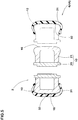
- FIG. 1 illustrates an exploded perspective view of a rigid core 1.
- the rigid core 1 comprises a core main body 2 having a center hole 3, a cylindrical center piece 4 being configured to be inserted into the center hole 3, and a pair of side plates 5 each arranged on axially both sides of the core main body 2.
- the core main body 2 is configured as a ring shape having an outer surface including a tire molding surface 6 which corresponds to an inner surface of a pneumatic tire to be molded.
- the pneumatic tire comprises a toroidal shape having a tread portion, a sidewall portion, and a bead portion.
- the core main body 2 has a round shape viewed from one of the side plate (hereinafter, it may be referred as "side shape") with a concentric center hole 3.
- the core main body 2 comprises a plurality of circumferentially divided core segments 10.
- the core segments 10 comprise a first core segment 10A and a second core segment 10B which are alternately arranged in the circumferential direction.
- the first core segment 10A includes a pair of inclined end faces 11 such that a circumferential length between end faces 11 reduces radially inward.
- the first core segment 10A has a fan-shaped side view.
- the second core segments 10B includes a pair of inclined end faces 12 such that a circumferential length between end faces 12 increases radially inward.
- the core main body 2 comprises eight core segments 10 including four first and second core segments each.
- the core main body 2 may form the tire molding surface 6 that corresponds to the inner surface of the pneumatic tire by connecting the end face 11 of the first core segment 10A and the end face 12 of the second core segment 10B one another so that respective outer surfaces 16 of the core segments 10 continue in the circumferential direction (connecting state).
- each core segment 10 is movable in the radial direction of the tire.
- the respective second segments 10B can be movable radially inward at first, and then the respective first segments 10A can be movable radially inward.
- each core segment 10 is provided with a dovetail tenon 14 extending in the axial direction of the tire.
- the dovetail tenon 14 faces in the center hole 3 and is positioned a circumferential middle of the inner surface 13 of the core segment 10.
- the center piece 4 has a cylindrical shape having an outer diameter approximately same with an inner diameter of the center hole 3.
- the center piece 4 is provided on its outer surface with a plurality of dovetail grooves 15 where the respective dovetail tenons 14 can be inserted to engage.
- the respective dovetail tenons 14 can be engaged with the respective dovetail grooves 15.
- the center piece 4 and the core segments 10 can be firmly fixed one another while allowing only a relative motion in the axial direction of the tire.
- a first side plate 5L is firmly fixed to one side of the center piece 4, and a second side plate 5U is detachably fixed to the other side of the center piece 4.
- Each side plate 5L and 5U can prevent from axial motion of each core segment 10 in relation to the center piece 4, thereby providing a firmly fixed core main body 2 with the connecting state.
- the second side plate 5U is detached from the center piece 4 at first, and then the center piece 4 with the first side plate 5L is pulled up from the center hole 3 of the core main body 2. Then the second core segments 10B may be moved radially inward in order to remove it from the center hole 3.
- FIG. 3 illustrates a cross-sectional view of one of the core segments 10 taken along a radial direction of the tire.
- the core segment 10 comprises a support base 20 forming an inner surface 13 of the center hole 3, and a segment main body 21 having an outer surface 16.
- the tire molding surface 6 is formed by continuously connecting the respective outer surfaces 16 of the segment main bodies 21.
- the inner surface 13 of the support base 20 is provided with the dovetail tenons 14 for connecting the center piece 4.
- the support base 20 is firmly fixed to the segment main body 21 at its axially both ends.
- the respective segment main body 21 may be made of metallic material having an excellent thermal conductivity, e.g., aluminum alloy.
- the outer surface 16 comprises an upper portion 23 located radially outward with respect to a maximum width position 22 of the core segment 10, and a lower portion 24 located radially inward with respect to the maximum width position 22.
- the upper portion 23 comprises a tread forming portion 28, and a pair of shoulder forming portions 29.
- the tread forming portion 28 is an approximately flatly extending surface including a core equator C to mold an inner surface of the tread portion of the tire.
- Each of the shoulder forming portion 29 extends from the tread forming portion 28 to the maximum width position 22 of the core segment 10 in a curved fashion to mold an inner surface of the shoulder and sidewall portions of the tire.
- the lower portion 24 comprises a curved portion 25, and a straight portion 26.
- the curved portion 25 extends radially inward from the maximum width position 22 in an S-shaped manner.
- the straight portion 26 extends radially inward from the curved portion 25 in a straight manner.
- the curved portion 25 includes a convexly curved portion 25a with a radius of rl and its center located inwardly of the segment main body 21, and a concave curved portion 25b with a radius of r2 and its center located outwardly of the segment main body 21.
- the lower portion 24 can mold an inner surface of the sidewall and bead portions of the tire.
- a method for manufacturing a pneumatic using the rigid core 1 comprises a green tire forming process, a vulcanization process, and a core removal process from the tire.
- the green tire forming process unvulcanized rubber components with sticky can be arranged on the outer surface 16 of the rigid core 1 to form a green tire, thereby forming a green tire on the rigid core.
- an inner liner rubber, a carcass ply, a belt ply, a bead core, a clinch rubber, a sidewall rubber, and a tread rubber may be used.
- a various kinds of method may be employed, e.g.
- the green tire 30 with the rigid core 1 is placed in a vulcanization mold 7 so that the green tire 30 is vulcanized and molded by a cavity formed between the rigid core 1 and the vulcanization mold 7.
- the core segments 10 are pulled out radially inward from the vulcanized tire 31.
- the core segments firmly adhere to the inner surface 32 of the tire 31, it can be difficult to tear off the core segments from the tire 31. Accordingly, a problem that the tire 31 is deformed undesirably may be caused when one of the core segments is forced to pull radially inward.
- this conventional proposal may offer a long cycle time.
- each core segment 10 comprises the outer surface 16 having a surface roughness Ra in a range of from 2.0 to 20.0 ⁇ m. Since the surface with the surface roughness Ra may offer an excellent adhesiveness with unvulcanized rubber components, the unvulcanized rubber components can be adhered on a correct position of the rigid core 1 during the green tire forming process. Furthermore, an excellent detachability between the core segments 10 and the inner surface 32 of the tire 31 after vulcanization can be offered, thereby preventing from undesirable deformation of the tire 31 caused by a poor detachability between the core segments 10 and the inner surface 32 while reducing cooling time of the rigid core 1. Accordingly, the present invention may offer an excellent productivity of the tire by reducing the time of the core removal process.
- the surface roughness Ra refers to arithmetic average roughness Ra defined by JIS B0601-2001.
- the surface roughness Ra is less than 2.0 ⁇ m, an excellent detachability between the inner surface of the tire and the core segments 10 may not be offered, thereby lowering the productivity of the tire due to undesirable long cycle time of the core removal process.
- the surface roughness Ra is more than 20.0 ⁇ m, the adhesiveness between the core segment and the unvulcanized rubber components may lower, thereby lowering uniformity of the tire due to unvulcanized rubber components arranged on an incorrect position at the green tire forming process.
- the lower limit of the surface roughness Ra of the outer surface 16 of the core segments 10 may be set in a range of not less than 5.0 ⁇ m, more preferably not less than 10 ⁇ m.
- the upper limit of the surface roughness Ra of the outer surface 16 of the core segments 10 may be set in a range of not more than 18 ⁇ m, more preferably not more than 15 ⁇ m.
- Such a core segment 10 having the surface roughness may further improve the advantages described above.
- the lower portion 24 of the core segment 10 has an area smaller than that of the upper portion 23.
- the lower portion 24 includes a steep curved portion 25 and the straight portion 26. Accordingly, molding failure may be caused in the green tire molding process such as slippage or separation of a rubber component adhered on the lower portion 24 prior to vulcanization.
- the lower portion 24 has a surface roughness Ra smaller than that of the upper portion 23 to prevent from slippage of the rubber member against the lower portion 24.
- the bead portion of the tire is separated from the lower portion 24 at the beginning, thereby entering the air into a gap therebetween. Then the whole inner surface 32 of the tire 31 can be separated from the core segments 10. Accordingly, it is important that ease of separation of the tire to the lower portion 24.
- the lower portion 24 of the core segment 10 has a surface roughness Ra in a range of not less than 10 ⁇ m, more preferably not less than 15 ⁇ m.
- the shoulder forming portions 29 are separated from the inner surface of the tire at the beginning, thereby entering the air into a gap therebetween. Then the tread forming portion 28 is separated from the inner surface of the tire. Accordingly, the shoulder forming portions 29 preferably have a surface roughness Ra larger than that of the tread forming portion 28. Thus, the upper portion 23 may be separated easily from the inner surface of the tire.
- a radial force variation (RFV) of each test tire manufactured by each of the rigid cores was measured using a uniformity measurement machine in accordance with uniformity test conditions of JASO C607: 2000. The test results are indicated using an index of Ex.1 being 100. The larger the value, the poorer the uniformity is. This means that a large slippage of a rubber component happened in the green tire molding process.
- the rigid cores in accordance with the present invention may prevent from slippage of a rubber component during the green tire molding process while shortening cycle time of rigid core removal process.
Landscapes
- Engineering & Computer Science (AREA)
- Mechanical Engineering (AREA)
- Moulds For Moulding Plastics Or The Like (AREA)
- Tyre Moulding (AREA)
- Heating, Cooling, Or Curing Plastics Or The Like In General (AREA)
Claims (3)
- Starrer Kern (1), umfassend:einen ringförmigen Kernhauptkörper (2), der eine Reifenformgebungsfläche (6) zum Formen einer Innenfläche eines Luftreifens aufweist;wobei der Kernhauptkörper (2) eine Vielzahl von in Umfangsrichtung unterteilten Kernsegmenten (10) umfasst, die jeweils entlang einer Reifenradialrichtung bewegbar sind; undjedes Kernsegment (10) eine Außenfläche (16) umfasst, die die Reifenformgebungsfläche (6) bildet,wobei die Außenfläche (16) jedes Kernsegments (10) einen oberen Abschnitt (23), der radial außen mit Bezug auf eine Position maximaler Breite (22) des Kernsegments (10) gelegen ist, und einen unteren Abschnitt (24) umfasst, der radial innen mit Bezug auf die Position maximaler Breite (22) des Kernsegments (10) gelegen ist,dadurch gekennzeichnet, dassdie Außenfläche (16) jedes Kernsegments (10) eine Oberflächenrauheit Ra von 2,0 bis 20,0 µm aufweist, undder untere Abschnitt (24) eine Oberflächenrauheit Ra aufweist, die kleiner ist als die des oberen Abschnitts (23).
- Starrer Kern (1) nach Anspruch 1, wobei der untere Abschnitt (24) die Oberflächenrauheit Ra in einem Bereich von nicht weniger als 10 µm aufweist.
- Verfahren zum Herstellen eines Luftreifens unter Verwendung des starren Kerns (1) nach Anspruch 1 oder 2, wobei das Verfahren umfasst:einen Rohrreifen-Formgebungsprozess zum Bilden eines Rohreifens durch Anordnen einer unvulkanisierten Kautschukkomponente auf der Reifenformgebungsfläche (6) des starren Kerns (1);einen Vulkanisationsprozess zum Vulkanisierens des Rohrreifens mit dem starren Kern (1) in einer Vulkanisationsform, um einen vulkanisierten Reifen zu bilden; undeinen Kernentnahmeprozess, um die Kernsegmente (10) des starren Kerns (1) durch Ziehen der Kernsegmente (10) in Richtung radial einwärts des Reifens aus dem vulkanisieren Reifen zu entnehmen.
Applications Claiming Priority (2)
| Application Number | Priority Date | Filing Date | Title |
|---|---|---|---|
| JP2012214849A JP5681685B2 (ja) | 2012-09-27 | 2012-09-27 | 剛性中子及びそれを用いた空気入りタイヤの製造方法 |
| PCT/JP2013/072146 WO2014050363A1 (ja) | 2012-09-27 | 2013-08-20 | 剛性中子及びそれを用いた空気入りタイヤの製造方法 |
Publications (3)
| Publication Number | Publication Date |
|---|---|
| EP2902178A1 EP2902178A1 (de) | 2015-08-05 |
| EP2902178A4 EP2902178A4 (de) | 2016-05-25 |
| EP2902178B1 true EP2902178B1 (de) | 2018-12-26 |
Family
ID=50387774
Family Applications (1)
| Application Number | Title | Priority Date | Filing Date |
|---|---|---|---|
| EP13840367.0A Not-in-force EP2902178B1 (de) | 2012-09-27 | 2013-08-20 | Starrer kern und verfahren zur herstellung eines luftreifens damit |
Country Status (5)
| Country | Link |
|---|---|
| US (1) | US10239269B2 (de) |
| EP (1) | EP2902178B1 (de) |
| JP (1) | JP5681685B2 (de) |
| CN (1) | CN104640690B (de) |
| WO (1) | WO2014050363A1 (de) |
Families Citing this family (5)
| Publication number | Priority date | Publication date | Assignee | Title |
|---|---|---|---|---|
| JP6251084B2 (ja) * | 2014-03-07 | 2017-12-20 | 住友ゴム工業株式会社 | タイヤ形成用の剛性中子 |
| JP6374779B2 (ja) * | 2014-12-01 | 2018-08-15 | 住友ゴム工業株式会社 | タイヤ形成用の剛性中子 |
| DE102017206655B4 (de) * | 2017-04-20 | 2020-07-09 | Contitech Luftfedersysteme Gmbh | Einrichtung zum Vulkanisieren eines Rohlings aus elastomerem Material |
| CN108943783B (zh) * | 2018-09-09 | 2023-06-23 | 上海医立泰生物科技有限公司 | 一种食管支架编织工装及其应用方法 |
| CN118025644B (zh) * | 2024-03-19 | 2025-08-26 | 威海市润通橡胶有限公司 | 一种便于存取的橡胶胎胚存放装置 |
Family Cites Families (14)
| Publication number | Priority date | Publication date | Assignee | Title |
|---|---|---|---|---|
| JPH02147411A (ja) * | 1988-11-30 | 1990-06-06 | Sumitomo Rubber Ind Ltd | 空気入りタイヤ及びその加硫金型 |
| EP0591745A3 (de) * | 1992-10-07 | 1994-10-12 | Michelin & Cie | Reifenform und Verfahren zum Formen von Reifen. |
| JPH07195380A (ja) * | 1993-12-28 | 1995-08-01 | Bridgestone Corp | タイヤ加硫用ブラダー及びタイヤ加硫方法 |
| US6113833A (en) * | 1997-07-22 | 2000-09-05 | Bridgestone Corporation | Segmented toroidal core for manufacturing pneumatic tires |
| JP3751128B2 (ja) * | 1997-08-08 | 2006-03-01 | 株式会社ブリヂストン | タイヤ製造用内型の取外し装置 |
| JP2003320595A (ja) * | 2002-04-30 | 2003-11-11 | Bridgestone Corp | タイヤ製造用コアの製造方法 |
| US20060134250A1 (en) * | 2004-12-22 | 2006-06-22 | Henrotte Eric M | Method and apparatus to vent a mold |
| JP2007136998A (ja) * | 2005-11-22 | 2007-06-07 | Toyo Tire & Rubber Co Ltd | ゴム成形体の射出成形方法 |
| JP2007253412A (ja) * | 2006-03-22 | 2007-10-04 | Yokohama Rubber Co Ltd:The | タイヤ成形用剛性中子 |
| JP2007320248A (ja) * | 2006-06-02 | 2007-12-13 | Bridgestone Corp | 空気入りタイヤの製造方法、加硫モールド、及び、空気入りタイヤ |
| EP2085201A1 (de) | 2008-01-30 | 2009-08-05 | Continental Aktiengesellschaft | Reifenvulkanisierform und mit dieser Reifenvulkanisierform hergestellter Reifen |
| JP5113861B2 (ja) | 2010-02-15 | 2013-01-09 | 住友ゴム工業株式会社 | 空気入りタイヤの製造方法、及びそれに用いる剛性中子 |
| JP5438545B2 (ja) | 2010-02-19 | 2014-03-12 | 住友ゴム工業株式会社 | 空気入りタイヤの製造方法 |
| JP4920760B2 (ja) * | 2010-04-08 | 2012-04-18 | 東洋ゴム工業株式会社 | 空気入りタイヤ、タイヤモールド及び空気入りタイヤの製造方法 |
-
2012
- 2012-09-27 JP JP2012214849A patent/JP5681685B2/ja active Active
-
2013
- 2013-08-20 WO PCT/JP2013/072146 patent/WO2014050363A1/ja not_active Ceased
- 2013-08-20 CN CN201380047779.6A patent/CN104640690B/zh active Active
- 2013-08-20 US US14/426,057 patent/US10239269B2/en active Active
- 2013-08-20 EP EP13840367.0A patent/EP2902178B1/de not_active Not-in-force
Non-Patent Citations (1)
| Title |
|---|
| None * |
Also Published As
| Publication number | Publication date |
|---|---|
| US10239269B2 (en) | 2019-03-26 |
| US20150210026A1 (en) | 2015-07-30 |
| EP2902178A1 (de) | 2015-08-05 |
| CN104640690A (zh) | 2015-05-20 |
| EP2902178A4 (de) | 2016-05-25 |
| WO2014050363A1 (ja) | 2014-04-03 |
| JP2014069333A (ja) | 2014-04-21 |
| JP5681685B2 (ja) | 2015-03-11 |
| CN104640690B (zh) | 2017-05-10 |
Similar Documents
| Publication | Publication Date | Title |
|---|---|---|
| EP2698243B1 (de) | Manschettenlose Reifenbautrommel | |
| EP2902178B1 (de) | Starrer kern und verfahren zur herstellung eines luftreifens damit | |
| EP2698244B1 (de) | Manschettenlose Reifenbautrommel mit auswechselbaren Breitenelementen | |
| EP2464507B1 (de) | Verfahren und anlage zur herstellung von reifen für fahrzeugräder | |
| EP2669078A1 (de) | Reifenvulkanisierform und Herstellungsverfahren für einen Reifen | |
| EP1537986A1 (de) | Reifenherstellungsverfahren und einrichtung zur herstellung eines rohreifens | |
| JP5667433B2 (ja) | タイヤ加硫金型及び空気入りタイヤの製造方法 | |
| EP2805809B1 (de) | Verfahren zur Herstellung von Motorradreifen | |
| EP2818291B1 (de) | Starrer kern zum formen eines reifens | |
| EP2038110B1 (de) | Verfahren und vorrichtung zur herstellung von luftreifen | |
| JP4263755B1 (ja) | 空気入りタイヤの製造方法 | |
| EP2038109A1 (de) | Verfahren und vorrichtung zur herstellung von luftreifen | |
| JP5066220B2 (ja) | 空気入りタイヤ及びその製造方法 | |
| JP2018012218A (ja) | Sot構造の空気入りタイヤの製造方法 | |
| US10328651B2 (en) | Rigid core mold and method for manufacturing pneumatic tire using the same | |
| US9144947B2 (en) | Rigid core for forming tire | |
| JP6196433B2 (ja) | 空気入りタイヤの製造方法 | |
| JP2011098533A (ja) | 空気入りタイヤの製造方法及び空気入りタイヤ | |
| JP5536391B2 (ja) | 更生タイヤの製造方法及び製造装置 | |
| JP2024104232A (ja) | 生タイヤの製造方法、空気入りタイヤの製造方法、生タイヤの製造装置及び空気入りタイヤ | |
| CN104185541B (zh) | 用于形成轮胎的刚性型芯 | |
| JP5767509B2 (ja) | 空気入りタイヤの製造方法 | |
| JP2005178038A (ja) | 更生タイヤの製造方法及びプレキュアトレッド体 | |
| KR20010088682A (ko) | 그린타이어 제조방법 |
Legal Events
| Date | Code | Title | Description |
|---|---|---|---|
| PUAI | Public reference made under article 153(3) epc to a published international application that has entered the european phase |
Free format text: ORIGINAL CODE: 0009012 |
|
| 17P | Request for examination filed |
Effective date: 20150327 |
|
| AK | Designated contracting states |
Kind code of ref document: A1 Designated state(s): AL AT BE BG CH CY CZ DE DK EE ES FI FR GB GR HR HU IE IS IT LI LT LU LV MC MK MT NL NO PL PT RO RS SE SI SK SM TR |
|
| AX | Request for extension of the european patent |
Extension state: BA ME |
|
| DAX | Request for extension of the european patent (deleted) | ||
| RA4 | Supplementary search report drawn up and despatched (corrected) |
Effective date: 20160421 |
|
| RIC1 | Information provided on ipc code assigned before grant |
Ipc: B29D 30/12 20060101AFI20160415BHEP Ipc: B29C 33/02 20060101ALI20160415BHEP |
|
| GRAP | Despatch of communication of intention to grant a patent |
Free format text: ORIGINAL CODE: EPIDOSNIGR1 |
|
| STAA | Information on the status of an ep patent application or granted ep patent |
Free format text: STATUS: GRANT OF PATENT IS INTENDED |
|
| RIC1 | Information provided on ipc code assigned before grant |
Ipc: B29C 33/02 20060101ALI20180711BHEP Ipc: B29D 30/06 20060101ALI20180711BHEP Ipc: B29D 30/12 20060101AFI20180711BHEP Ipc: B29C 33/42 20060101ALI20180711BHEP Ipc: B29L 30/00 20060101ALI20180711BHEP |
|
| INTG | Intention to grant announced |
Effective date: 20180810 |
|
| GRAS | Grant fee paid |
Free format text: ORIGINAL CODE: EPIDOSNIGR3 |
|
| GRAA | (expected) grant |
Free format text: ORIGINAL CODE: 0009210 |
|
| STAA | Information on the status of an ep patent application or granted ep patent |
Free format text: STATUS: THE PATENT HAS BEEN GRANTED |
|
| AK | Designated contracting states |
Kind code of ref document: B1 Designated state(s): AL AT BE BG CH CY CZ DE DK EE ES FI FR GB GR HR HU IE IS IT LI LT LU LV MC MK MT NL NO PL PT RO RS SE SI SK SM TR |
|
| REG | Reference to a national code |
Ref country code: GB Ref legal event code: FG4D |
|
| REG | Reference to a national code |
Ref country code: CH Ref legal event code: EP |
|
| REG | Reference to a national code |
Ref country code: AT Ref legal event code: REF Ref document number: 1080820 Country of ref document: AT Kind code of ref document: T Effective date: 20190115 |
|
| REG | Reference to a national code |
Ref country code: DE Ref legal event code: R096 Ref document number: 602013048950 Country of ref document: DE |
|
| REG | Reference to a national code |
Ref country code: IE Ref legal event code: FG4D |
|
| PG25 | Lapsed in a contracting state [announced via postgrant information from national office to epo] |
Ref country code: FI Free format text: LAPSE BECAUSE OF FAILURE TO SUBMIT A TRANSLATION OF THE DESCRIPTION OR TO PAY THE FEE WITHIN THE PRESCRIBED TIME-LIMIT Effective date: 20181226 Ref country code: BG Free format text: LAPSE BECAUSE OF FAILURE TO SUBMIT A TRANSLATION OF THE DESCRIPTION OR TO PAY THE FEE WITHIN THE PRESCRIBED TIME-LIMIT Effective date: 20190326 Ref country code: HR Free format text: LAPSE BECAUSE OF FAILURE TO SUBMIT A TRANSLATION OF THE DESCRIPTION OR TO PAY THE FEE WITHIN THE PRESCRIBED TIME-LIMIT Effective date: 20181226 Ref country code: LV Free format text: LAPSE BECAUSE OF FAILURE TO SUBMIT A TRANSLATION OF THE DESCRIPTION OR TO PAY THE FEE WITHIN THE PRESCRIBED TIME-LIMIT Effective date: 20181226 Ref country code: LT Free format text: LAPSE BECAUSE OF FAILURE TO SUBMIT A TRANSLATION OF THE DESCRIPTION OR TO PAY THE FEE WITHIN THE PRESCRIBED TIME-LIMIT Effective date: 20181226 Ref country code: NO Free format text: LAPSE BECAUSE OF FAILURE TO SUBMIT A TRANSLATION OF THE DESCRIPTION OR TO PAY THE FEE WITHIN THE PRESCRIBED TIME-LIMIT Effective date: 20190326 |
|
| REG | Reference to a national code |
Ref country code: NL Ref legal event code: MP Effective date: 20181226 |
|
| REG | Reference to a national code |
Ref country code: LT Ref legal event code: MG4D |
|
| PG25 | Lapsed in a contracting state [announced via postgrant information from national office to epo] |
Ref country code: AL Free format text: LAPSE BECAUSE OF FAILURE TO SUBMIT A TRANSLATION OF THE DESCRIPTION OR TO PAY THE FEE WITHIN THE PRESCRIBED TIME-LIMIT Effective date: 20181226 Ref country code: RS Free format text: LAPSE BECAUSE OF FAILURE TO SUBMIT A TRANSLATION OF THE DESCRIPTION OR TO PAY THE FEE WITHIN THE PRESCRIBED TIME-LIMIT Effective date: 20181226 Ref country code: GR Free format text: LAPSE BECAUSE OF FAILURE TO SUBMIT A TRANSLATION OF THE DESCRIPTION OR TO PAY THE FEE WITHIN THE PRESCRIBED TIME-LIMIT Effective date: 20190327 Ref country code: SE Free format text: LAPSE BECAUSE OF FAILURE TO SUBMIT A TRANSLATION OF THE DESCRIPTION OR TO PAY THE FEE WITHIN THE PRESCRIBED TIME-LIMIT Effective date: 20181226 |
|
| REG | Reference to a national code |
Ref country code: AT Ref legal event code: MK05 Ref document number: 1080820 Country of ref document: AT Kind code of ref document: T Effective date: 20181226 |
|
| PG25 | Lapsed in a contracting state [announced via postgrant information from national office to epo] |
Ref country code: NL Free format text: LAPSE BECAUSE OF FAILURE TO SUBMIT A TRANSLATION OF THE DESCRIPTION OR TO PAY THE FEE WITHIN THE PRESCRIBED TIME-LIMIT Effective date: 20181226 |
|
| PG25 | Lapsed in a contracting state [announced via postgrant information from national office to epo] |
Ref country code: CZ Free format text: LAPSE BECAUSE OF FAILURE TO SUBMIT A TRANSLATION OF THE DESCRIPTION OR TO PAY THE FEE WITHIN THE PRESCRIBED TIME-LIMIT Effective date: 20181226 Ref country code: PT Free format text: LAPSE BECAUSE OF FAILURE TO SUBMIT A TRANSLATION OF THE DESCRIPTION OR TO PAY THE FEE WITHIN THE PRESCRIBED TIME-LIMIT Effective date: 20190426 Ref country code: IT Free format text: LAPSE BECAUSE OF FAILURE TO SUBMIT A TRANSLATION OF THE DESCRIPTION OR TO PAY THE FEE WITHIN THE PRESCRIBED TIME-LIMIT Effective date: 20181226 Ref country code: ES Free format text: LAPSE BECAUSE OF FAILURE TO SUBMIT A TRANSLATION OF THE DESCRIPTION OR TO PAY THE FEE WITHIN THE PRESCRIBED TIME-LIMIT Effective date: 20181226 Ref country code: PL Free format text: LAPSE BECAUSE OF FAILURE TO SUBMIT A TRANSLATION OF THE DESCRIPTION OR TO PAY THE FEE WITHIN THE PRESCRIBED TIME-LIMIT Effective date: 20181226 |
|
| PG25 | Lapsed in a contracting state [announced via postgrant information from national office to epo] |
Ref country code: SK Free format text: LAPSE BECAUSE OF FAILURE TO SUBMIT A TRANSLATION OF THE DESCRIPTION OR TO PAY THE FEE WITHIN THE PRESCRIBED TIME-LIMIT Effective date: 20181226 Ref country code: RO Free format text: LAPSE BECAUSE OF FAILURE TO SUBMIT A TRANSLATION OF THE DESCRIPTION OR TO PAY THE FEE WITHIN THE PRESCRIBED TIME-LIMIT Effective date: 20181226 Ref country code: IS Free format text: LAPSE BECAUSE OF FAILURE TO SUBMIT A TRANSLATION OF THE DESCRIPTION OR TO PAY THE FEE WITHIN THE PRESCRIBED TIME-LIMIT Effective date: 20190426 Ref country code: SM Free format text: LAPSE BECAUSE OF FAILURE TO SUBMIT A TRANSLATION OF THE DESCRIPTION OR TO PAY THE FEE WITHIN THE PRESCRIBED TIME-LIMIT Effective date: 20181226 Ref country code: EE Free format text: LAPSE BECAUSE OF FAILURE TO SUBMIT A TRANSLATION OF THE DESCRIPTION OR TO PAY THE FEE WITHIN THE PRESCRIBED TIME-LIMIT Effective date: 20181226 |
|
| REG | Reference to a national code |
Ref country code: DE Ref legal event code: R097 Ref document number: 602013048950 Country of ref document: DE |
|
| PG25 | Lapsed in a contracting state [announced via postgrant information from national office to epo] |
Ref country code: AT Free format text: LAPSE BECAUSE OF FAILURE TO SUBMIT A TRANSLATION OF THE DESCRIPTION OR TO PAY THE FEE WITHIN THE PRESCRIBED TIME-LIMIT Effective date: 20181226 Ref country code: DK Free format text: LAPSE BECAUSE OF FAILURE TO SUBMIT A TRANSLATION OF THE DESCRIPTION OR TO PAY THE FEE WITHIN THE PRESCRIBED TIME-LIMIT Effective date: 20181226 |
|
| PLBE | No opposition filed within time limit |
Free format text: ORIGINAL CODE: 0009261 |
|
| STAA | Information on the status of an ep patent application or granted ep patent |
Free format text: STATUS: NO OPPOSITION FILED WITHIN TIME LIMIT |
|
| 26N | No opposition filed |
Effective date: 20190927 |
|
| PG25 | Lapsed in a contracting state [announced via postgrant information from national office to epo] |
Ref country code: SI Free format text: LAPSE BECAUSE OF FAILURE TO SUBMIT A TRANSLATION OF THE DESCRIPTION OR TO PAY THE FEE WITHIN THE PRESCRIBED TIME-LIMIT Effective date: 20181226 |
|
| PG25 | Lapsed in a contracting state [announced via postgrant information from national office to epo] |
Ref country code: TR Free format text: LAPSE BECAUSE OF FAILURE TO SUBMIT A TRANSLATION OF THE DESCRIPTION OR TO PAY THE FEE WITHIN THE PRESCRIBED TIME-LIMIT Effective date: 20181226 |
|
| GBPC | Gb: european patent ceased through non-payment of renewal fee |
Effective date: 20190820 |
|
| PG25 | Lapsed in a contracting state [announced via postgrant information from national office to epo] |
Ref country code: MC Free format text: LAPSE BECAUSE OF FAILURE TO SUBMIT A TRANSLATION OF THE DESCRIPTION OR TO PAY THE FEE WITHIN THE PRESCRIBED TIME-LIMIT Effective date: 20181226 Ref country code: LU Free format text: LAPSE BECAUSE OF NON-PAYMENT OF DUE FEES Effective date: 20190820 Ref country code: CH Free format text: LAPSE BECAUSE OF NON-PAYMENT OF DUE FEES Effective date: 20190831 Ref country code: LI Free format text: LAPSE BECAUSE OF NON-PAYMENT OF DUE FEES Effective date: 20190831 |
|
| REG | Reference to a national code |
Ref country code: BE Ref legal event code: MM Effective date: 20190831 |
|
| PG25 | Lapsed in a contracting state [announced via postgrant information from national office to epo] |
Ref country code: FR Free format text: LAPSE BECAUSE OF NON-PAYMENT OF DUE FEES Effective date: 20190831 Ref country code: IE Free format text: LAPSE BECAUSE OF NON-PAYMENT OF DUE FEES Effective date: 20190820 |
|
| PG25 | Lapsed in a contracting state [announced via postgrant information from national office to epo] |
Ref country code: BE Free format text: LAPSE BECAUSE OF NON-PAYMENT OF DUE FEES Effective date: 20190831 Ref country code: GB Free format text: LAPSE BECAUSE OF NON-PAYMENT OF DUE FEES Effective date: 20190820 |
|
| PG25 | Lapsed in a contracting state [announced via postgrant information from national office to epo] |
Ref country code: CY Free format text: LAPSE BECAUSE OF FAILURE TO SUBMIT A TRANSLATION OF THE DESCRIPTION OR TO PAY THE FEE WITHIN THE PRESCRIBED TIME-LIMIT Effective date: 20181226 |
|
| PG25 | Lapsed in a contracting state [announced via postgrant information from national office to epo] |
Ref country code: MT Free format text: LAPSE BECAUSE OF FAILURE TO SUBMIT A TRANSLATION OF THE DESCRIPTION OR TO PAY THE FEE WITHIN THE PRESCRIBED TIME-LIMIT Effective date: 20181226 Ref country code: HU Free format text: LAPSE BECAUSE OF FAILURE TO SUBMIT A TRANSLATION OF THE DESCRIPTION OR TO PAY THE FEE WITHIN THE PRESCRIBED TIME-LIMIT; INVALID AB INITIO Effective date: 20130820 |
|
| PG25 | Lapsed in a contracting state [announced via postgrant information from national office to epo] |
Ref country code: MK Free format text: LAPSE BECAUSE OF FAILURE TO SUBMIT A TRANSLATION OF THE DESCRIPTION OR TO PAY THE FEE WITHIN THE PRESCRIBED TIME-LIMIT Effective date: 20181226 |
|
| P01 | Opt-out of the competence of the unified patent court (upc) registered |
Effective date: 20230510 |
|
| PGFP | Annual fee paid to national office [announced via postgrant information from national office to epo] |
Ref country code: DE Payment date: 20240702 Year of fee payment: 12 |
|
| REG | Reference to a national code |
Ref country code: DE Ref legal event code: R119 Ref document number: 602013048950 Country of ref document: DE |