EP2902184A1 - Procédé pour réaliser des lignes d'affaiblissement sur un découpe pour une boîte pliante - Google Patents
Procédé pour réaliser des lignes d'affaiblissement sur un découpe pour une boîte pliante Download PDFInfo
- Publication number
- EP2902184A1 EP2902184A1 EP15153292.6A EP15153292A EP2902184A1 EP 2902184 A1 EP2902184 A1 EP 2902184A1 EP 15153292 A EP15153292 A EP 15153292A EP 2902184 A1 EP2902184 A1 EP 2902184A1
- Authority
- EP
- European Patent Office
- Prior art keywords
- blank
- wall
- corner
- pair
- weakening lines
- Prior art date
- Legal status (The legal status is an assumption and is not a legal conclusion. Google has not performed a legal analysis and makes no representation as to the accuracy of the status listed.)
- Granted
Links
- 238000000034 method Methods 0.000 title claims abstract description 39
- 230000003313 weakening effect Effects 0.000 claims abstract description 92
- 239000000779 smoke Substances 0.000 claims description 13
- 230000008878 coupling Effects 0.000 claims description 11
- 238000010168 coupling process Methods 0.000 claims description 11
- 238000005859 coupling reaction Methods 0.000 claims description 11
- 239000012858 resilient material Substances 0.000 claims description 8
- 239000000463 material Substances 0.000 claims description 3
- 238000004806 packaging method and process Methods 0.000 claims description 2
- 230000000295 complement effect Effects 0.000 description 13
- 238000005520 cutting process Methods 0.000 description 13
- 229920003023 plastic Polymers 0.000 description 10
- 230000015572 biosynthetic process Effects 0.000 description 8
- 235000019504 cigarettes Nutrition 0.000 description 8
- 238000005259 measurement Methods 0.000 description 6
- 238000004519 manufacturing process Methods 0.000 description 3
- 229920000298 Cellophane Polymers 0.000 description 2
- 230000003247 decreasing effect Effects 0.000 description 2
- 239000000126 substance Substances 0.000 description 2
- 230000037303 wrinkles Effects 0.000 description 2
- 238000013459 approach Methods 0.000 description 1
- 230000006866 deterioration Effects 0.000 description 1
- 238000010586 diagram Methods 0.000 description 1
- 238000004049 embossing Methods 0.000 description 1
- 238000005304 joining Methods 0.000 description 1
Images


Classifications
-
- B—PERFORMING OPERATIONS; TRANSPORTING
- B31—MAKING ARTICLES OF PAPER, CARDBOARD OR MATERIAL WORKED IN A MANNER ANALOGOUS TO PAPER; WORKING PAPER, CARDBOARD OR MATERIAL WORKED IN A MANNER ANALOGOUS TO PAPER
- B31F—MECHANICAL WORKING OR DEFORMATION OF PAPER, CARDBOARD OR MATERIAL WORKED IN A MANNER ANALOGOUS TO PAPER
- B31F1/00—Mechanical deformation without removing material, e.g. in combination with laminating
- B31F1/08—Creasing
-
- B—PERFORMING OPERATIONS; TRANSPORTING
- B31—MAKING ARTICLES OF PAPER, CARDBOARD OR MATERIAL WORKED IN A MANNER ANALOGOUS TO PAPER; WORKING PAPER, CARDBOARD OR MATERIAL WORKED IN A MANNER ANALOGOUS TO PAPER
- B31F—MECHANICAL WORKING OR DEFORMATION OF PAPER, CARDBOARD OR MATERIAL WORKED IN A MANNER ANALOGOUS TO PAPER
- B31F1/00—Mechanical deformation without removing material, e.g. in combination with laminating
- B31F1/07—Embossing, i.e. producing impressions formed by locally deep-drawing, e.g. using rolls provided with complementary profiles
-
- B—PERFORMING OPERATIONS; TRANSPORTING
- B65—CONVEYING; PACKING; STORING; HANDLING THIN OR FILAMENTARY MATERIAL
- B65B—MACHINES, APPARATUS OR DEVICES FOR, OR METHODS OF, PACKAGING ARTICLES OR MATERIALS; UNPACKING
- B65B19/00—Packaging rod-shaped or tubular articles susceptible to damage by abrasion or pressure, e.g. cigarettes, cigars, macaroni, spaghetti, drinking straws or welding electrodes
- B65B19/02—Packaging cigarettes
- B65B19/22—Wrapping the cigarettes; Packaging the cigarettes in containers formed by folding wrapping material around formers
- B65B19/228—Preparing and feeding blanks
-
- B—PERFORMING OPERATIONS; TRANSPORTING
- B31—MAKING ARTICLES OF PAPER, CARDBOARD OR MATERIAL WORKED IN A MANNER ANALOGOUS TO PAPER; WORKING PAPER, CARDBOARD OR MATERIAL WORKED IN A MANNER ANALOGOUS TO PAPER
- B31B—MAKING CONTAINERS OF PAPER, CARDBOARD OR MATERIAL WORKED IN A MANNER ANALOGOUS TO PAPER
- B31B2160/00—Shape of flexible containers
- B31B2160/10—Shape of flexible containers rectangular and flat, i.e. without structural provision for thickness of contents
-
- B—PERFORMING OPERATIONS; TRANSPORTING
- B31—MAKING ARTICLES OF PAPER, CARDBOARD OR MATERIAL WORKED IN A MANNER ANALOGOUS TO PAPER; WORKING PAPER, CARDBOARD OR MATERIAL WORKED IN A MANNER ANALOGOUS TO PAPER
- B31B—MAKING CONTAINERS OF PAPER, CARDBOARD OR MATERIAL WORKED IN A MANNER ANALOGOUS TO PAPER
- B31B50/00—Making rigid or semi-rigid containers, e.g. boxes or cartons
- B31B50/25—Surface scoring
Definitions
- the invention relates to a method for forming weakening lines in a blank intended for making a container, in particular a container for smoke articles.
- the weakening lines which are also known as crease lines, are the lines along which the blank is folded for making the corresponding container.
- the present invention finds particularly advantageous application in the production of packets and/or cartons of cigarettes of rigid type obtained from respective flat blanks of cardboard, card or similar material, provided with corner walls that have a transverse dimension that is variable along the longitudinal axis of the packet and/or the transverse axis of the carton.
- a rigid packet of cigarettes mainly consists of a container that is open at one end, of a lid, hinged to an end edge of the container, and of an inner frame fixed inside the container.
- Rigid packets that extend along a prevalent longitudinal axis and comprise a front wall, a rear wall, two lateral sides, a top wall and a bottom wall.
- the front wall and the rear wall are connected to the two sides by respective corner walls that have a transverse dimension that is variable along the longitudinal axis of the packet.
- transverse means a dimension measured transversely, more precisely on a plane that is orthogonal to the longitudinal axis of the packet.
- each corner wall has a transverse dimension that is variable linearly along the longitudinal axis of the packet.
- each corner wall comprises a triangular panel and is defined between two rectilinear edges, each connected respectively to the front wall or rear wall and to one of the lateral sides.
- the two edges extend from a common vertex, positioned at the top wall, or, respectively, the bottom wall, diverging from one another, along the longitudinal axis of the packet, moving away from the top wall, or, respectively, from the bottom wall.
- each corner wall comprises a lenticular panel that is concave towards the inside of the packet.
- each corner wall is defined between two arched curvilinear edges each connected respectively to the front wall or rear wall and to one of the lateral sides. In particular, the two edges extend diverging from a first common vertex and converging on a second common vertex.
- each corner wall comprises a panel that is convex towards the outside of the packet.
- each corner wall is defined between two arched curvilinear edges each connected respectively to the front wall or rear wall and to one of the lateral sides. More precisely, the two edges are defined by respective circumference arches that are symmetrical to one another with respect to a plane that is parallel to the longitudinal axis. The edges extend by diverging from a central zone of the lateral sides approaching the top wall and the bottom wall. In other words, the two edges are at a minimum distance at the central zone of the sides and at a maximum distance at the top wall and at the bottom wall.
- a drawback of this method is that the dinking machines do not enable weakening lines, and thus edges to be made that extend from a common vertex defining a very small angle, for example of the order of 5 degrees, or weakening lines that are tangent to one another or substantially tangent, or anyway weakening lines that are very near to one another.
- the prior art proposes forming only partially the weakening lines, i.e. not forming the zones in which the weakening lines are very near to one another, for example the zones in which the weakening lines should converge to form a common vertex or a tangent point.
- creasing threads are used, and respective creasing channels are used that have a lesser length than the length of the weakening lines to be formed.
- the creasing threads, and the respective creasing channels do not reproduce the aforesaid zone in which the weakening lines will have to be very near to one another, relying on the probability that the weakening lines, only partially formed by the respective creasing threads and creasing channels, meet, after folding of the blank, at the vertex or at the tangent point.
- This solution does not, however, ensure the required minimum precision requisite, with consequent deterioration of the aesthetic appeal of the packet.
- a creasing tool that enables weakening lines to be made that converge in a vertex.
- the creasing tool comprises two creasing threads that converge in a single creasing thread.
- the object of the present invention is to provide a method for forming weakening lines in a blank intended for making a container that is able to overcome the aforementioned drawbacks.
- a container of generic type made from a blank 100 having weakening lines, or crease lines, 104a, 104b, 105a, 105b, made with the method according to the present invention.
- the container 1 is of the rigid type, extends according to a substantially parallelpipedon structure around a main direction A and has inside a compartment V intended for housing one or more articles, which are not shown.
- the main direction A is the direction along which the container 1 extends prevalently.
- the container 1 comprises a front wall 2, a rear wall 3 facing the front wall 2, a pair of lateral sides 4, 5, an opening 6 and a bottom wall 7.
- the front wall 2 is substantially flat and extends parallel to the rear wall 3, whereas the two lateral sides 4, 5 (parallel to one another) are transverse thereto.
- the opening 6 and the bottom wall 7 are orthogonal to the main direction A and have a plurality of sides from which the front wall 2 and rear wall 3 and the lateral sides 4, 5 extend.
- the opening 6 and the bottom wall 7 have the same perimeter extent. Consequently, the perimeter of the bottom wall 7 is the same (in value) as that of the opening 6.
- bottom wall 7 has also the same geometry as the opening 6, but overturned with respect thereto.
- the container 1 comprises at least one first corner wall 8 and at least one second corner wall 9, each interposed between a lateral side 4, 5 and the respective front wall 2 or rear wall 3.
- the container 1 comprises at least two corner walls that are tilted both with respect to the front wall 2 or rear wall 3 and with respect to the side 4, 5.
- the first corner wall 8 and the second corner wall 9 have a transverse dimension that is variable along the main direction A of the container 1.
- first corner wall 8 and the second corner wall 9 have a transverse dimension that is variable linearly along the main direction A of the container 1.
- transverse means a dimension measured transversely (more precisely on a plane that is orthogonal) to the main direction A of the container 1.
- each corner wall 8, 9 extends between two edges 8a, 8b, 9a, 9b, each connected respectively to the front wall 2 or rear wall 3 and to the side wall 4, 5.
- edges 8a, 8b extend from a common vertex v1 positioned at the bottom wall 7 diverging from one another along the main direction A moving away from the bottom wall 7, whereas the edges 9a, 9b extend from a common vertex v2 positioned at the opening 6 diverging from one another along the main direction A moving away from the opening 6.
- the first corner wall 8 has a geometry that is complementary to that of the second corner wall 9.
- the sum of these transverse dimensions is maintained constant along the entire extent of the container along the main direction A.
- the first corner wall 8 has a transverse dimension increasing as it approaches the opening 6 and the second corner wall 9 has a transverse dimension decreasing in a manner that is complementary to the first corner wall 8.
- the two edges 8a, 8b of the first corner wall 8 extend diverging from one another, from the common vertex v1, along the main direction A approaching the opening 6.
- the two edges 9a, 9b of the second corner wall 9 extend diverging from one another, from the common vertex v2, along the main direction A approaching the bottom wall 7.
- edges 8a, 8b, 9a, 9b of the corner walls 8, 9 have a monotonic curve, i.e. do not have curvature changes.
- corner walls 8, 9 extend along the entire extent of the container 1, between a first end connected to the bottom wall 7 and a second end connected to the opening 6.
- the corner walls 8, 9 can have a partial extent, in which one end is connected to the bottom wall 7 or to the opening 6, whereas the other end is located in an intermediate zone of the longitudinal extent of the container 1.
- the corner walls 8, 9 have a triangular or trapezoidal geometry.
- the corner walls 8, 9 have a substantially planar conformation. More precisely, they lie on respective planes that are tilted by an angle comprised between 20 and 80 degrees, preferably comprised between 30 and 60 degrees, more preferably equal to 45 degrees, with respect to the adjacent side wall 4, 5.
- each corner wall 8, 9 can have a curved connecting surface between the side wall 4, 5 and the respective front wall 2 or rear wall 3.
- each corner wall 8, 9 has a conical or frustum-conical geometry.
- first 8 and the second corner wall 9 can be arranged at any corner between the front wall 2 or rear wall 3 and the respective side 4, 5.
- the container 1 comprises a pair of first corner walls 8 and a pair of second corner walls 9.
- the container 1 has four corner walls 8, 9, which in substance replace totally the sharp edges at right angle of normal containers.
- Each first corner wall 8 has a geometry that is complementary to that of a respective second corner wall 9 so as to maintain substantially constant the perimeter extent of each section of the container 1 transverse to the main direction A.
- each first corner wall 8 is symmetrical to the other first corner wall 8 with respect to a median plane that is transverse to the front wall 2 and parallel to the main direction A.
- each second corner wall 9 is symmetrical to the other second corner wall 9 with respect to the aforesaid median plane.
- each first 8 and/or second corner wall 9 is symmetrical to the other first 8 and/or second corner wall 9 with respect to the median plane which is transverse to the front wall 2 and parallel to the main direction A.
- first corner walls 8 are symmetrical to one another with respect to a plane parallel to the main direction A and connecting two opposite vertices of the bottom wall 7 (or to the opening 6) of the container 1.
- the second corner walls 9 are symmetrical to one another with respect to this plane.
- each first 8 and/or second corner wall 9 is symmetrical to the other first 8 and/or second corner wall 9 with respect to a plane parallel to the main direction A and connecting two opposite vertices of the bottom wall 7 or of the opening 6.
- the container 1 disclosed until now is preferably made from a flat blank 100, made of cardboard or the like ( figure 3 ).
- This blank 100 has a direction C of greater extent, corresponding to the main direction A of the container 1, and a substantially rectangular shape.
- the blank 100 comprises a plurality of panels 101 arranged in succession along the direction of greatest extent C of the blank that are each connected to the next one by a transverse weakening line 102, transverse to the direction of greatest extent C.
- These panels 101 define the front wall 2, the rear wall 3 and the bottom wall 7 of the container 1.
- the blank 100 comprises a pair of wings 103a, 103b arranged on opposite sides of one or more panels 101, in which each wing 103a, 103b defines an inner or outer face of a lateral wall 4, 5 of the container 1.
- the blank 100 comprises further a pair of first flaps 104 and a pair of second flaps 105 each interposed between a wing 103a, 103b and the respective panel 101.
- Each of the flaps 104, 105, of triangular shape has a transverse dimension that is variable along the direction of greatest extent C of the blank 100.
- transverse means a dimension that is transverse (more precisely orthogonal) to the direction of greatest extent C of the blank 100.
- each flap 104, 105 extends, along the direction of greatest extent C of the blank 100, between a first 104a, 105a and a second weakening line 104b, 105b.
- each flap 104, 105 along the direction of greatest extent C of the blank 100, is connected to the respective panel 101 by the first weakening line 104a, 105a and to the respective wing 103a, 103b by the second weakening line 104b, 105b.
- the measurement of the distance between the two weakening lines 104a and 104b and between the two weakening lines 105a and 105b of a respective single flap 104, 105 is variable along the direction of greatest extent C starting from a common vertex.
- the weakening lines 104a, 104b extend from a common vertex v1' positioned at the panel 101 intended for forming the bottom wall 7 of the container 1, diverging from one another along the direction of greatest extent C moving away from the panel 101 intended for forming the bottom wall 7, whereas the weakening lines 105a, 105b extend from a common vertex v2' positioned at a first cutting line 106a of the blank 100 intended for forming, partially, the opening 6 of the container 1, diverging from one another along the direction of greatest extent C moving away from the first cutting line 106a.
- the weakening lines 104a, 104b, 105a, 105b define the respective edges 8a, 8b, 9a, 9b of the corner walls 8, 9 of the container 1.
- each first flap 104 is delimited, transversely with respect to the direction of greatest extent C of the blank 100, by a second cutting line 106b, whereas each second flap 105 is delimited, transversely with respect to the direction of greatest extent C of the blank 100, by a third cutting line 106c.
- the flaps 104, 105 define respective circumscribed surfaces 107, 108 of the blank 100 of triangular shape.
- the first flap 104 has a geometry that is complementary to that of the second flap 105.
- the second weakening line 104b of the first flap 104 defines a contour that is complementary to the second weakening line 105b of the second flap 105.
- Each first flap 104 is complementary both to the other first flap 104, aligned therewith to define a single first corner wall 8 of the container 1, and to the second flap 105 with which it is associated to maintain constant the transverse dimension of the blank 100.
- each second flap 105 is complementary both to the other second flap 105, aligned therewith to define a single second corner wall 9 of the container 1, and to the first flap 104 with which it is associated to maintain constant the transverse dimension of the blank 100.
- the method, according to the present invention, for forming the weakening lines 104a, 104b, 105a and 105b, is disclosed below.
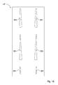
- an advancement line is indicated of a succession of blanks 100, shown schematically, from which, after folding, the containers 1 are obtained.
- the line L extends through a forming station F until a wrapping unit I is fed.
- the forming station F may or may not constitute an integrating part of a packaging machine H illustrated for the sake of simplicity with a dashed block.
- each blank 100 are subjected to a plastic deforming operation for forming respectively first convex portions 104' and second convex portions 105' ( figure 7 ).
- the first convex portions 104' are delimited peripherally by a first closed contour B defined by a first side b1, a second side b2 and a third side b3.
- first side b1 and the second side b2 define respectively the weakening lines 104a and 104b of the blank 100.
- the second convex portions 105' are peripherally delimited by a second closed contour S defined by a first side s1, a second side s2 and a third side s3.
- the first side s1 and the second side s2 define respectively the weakening lines 105a and 105b of the blank 100.
- the plastic deforming convexing operation can be obtained by a drawing operation that makes stepped contours that are permanently deformed.
- first 104' and second 105' convex portions that have a rounded cross section liked to the flat surface of the blank 100, and the orientation of which can be concave towards the interior or convex towards the exterior with reference to the container 1.
- the weakening lines 104a, 104b, 105a and 105b coincide with parts of the contour of the respective convex portions 104', 105' linked to the flat surface of the blank 100.
- first 104' and second 105' drawn portions that have a cross section shaped as a step between two flat surfaces of the blank 100 that are parallel but located at a short distance from one another, equal to the drawing depth.
- the weakening lines 104a, 104b, 105a and 105b coincide with parts of the step contour of the respective drawn portions 104', 105'.
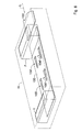
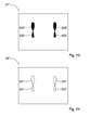
- the plastic deforming operation is achieved by drawing and it is performed, in the course of a stop of each blank 100 at the forming station F, by a pair of tools U1, U2 comprising a punch U1 and a corresponding counter-punch U2 cooperating between themselves and movable with reciprocating movement along a path that is transverse to the advancement line L.
- the tools U1, U2 are arranged on opposite sides of the advancement line L, and at least one of the tools U1, U2, in the case in point the punch U1, has projections 130 suitable for making, in cooperation with respective recesses 131 in the counter-punch U2 and in a manner that is suitable for coupling with the projections 130, the convex portions 104', 105'.
- the projections 130 and the recesses 131 have, in a plan view, substantially the same shape and dimension as the flaps 104, 105 to be deformed plastically.
- the counter-punch U2 is made of resilient material, so as to constitute a yielding contrasting element with respect to the projections 130 of the punch U1, with consequent formation of convex portions 104', 105' in each blank 100.
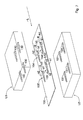
- the blanks 100 are fed continuously and the plastic deforming operation is achieved by drawing by a pair of rollers R1, R2 counter-rotating and cooperating together.
- the rollers R1, R2 have axes that are transverse to the advancement line L and are arranged on opposite sides to the latter.
- At least one of the rollers R1, R2, in the case in point the upper roller U1, has on the cylindrical surface 140 thereof projections 130' that are suitable for making, in cooperation with corresponding recesses 131' which are present on the cylindrical surface 141 of the lower roller R2 and which are suitable for coupling with the projections 130', the triangular convex portions 104', 105'.
- the lower roller R2 is made of resilient material, so as to constitute a yielding contrasting element with respect to the projections 130' of the upper roller R1, with consequent formation of convex portions 104', 105' in each blank 100.
- the blank 100 constitutes part of a strip defined by a succession of blanks joined together and arranged with their main directions A parallel to the advancement line L of the strip.
- the weakening lines 104a, 104b, 105a and 105b it is indifferent whether deformation occurs towards the exterior (“debossing") or towards the interior (“embossing") of the blank 100 inasmuch as the container 1 formed after folding of the blank 100 will anyway not have, at the corner walls 8, 9, convex zones of an appreciable dimension towards the inside or the outside.
- the method disclosed above can be advantageously used to make packets of cigarettes of the rigid type obtained from respective flat blanks of cardboard, card or similar material of the type disclosed below.
- the method disclosed above can be advantageously used to make weakening lines 304a, 304b, 305a and 305b of a blank 300 and weakening lines 352a, 352b, 353a and 353b of a blank 350 intended to form, after folding, a packet 201 of the type illustrated in figures 9 to 11 .
- packets disclosed are of the hinged lid type, nevertheless, the present invention refers to any packet for smoke articles, whether with a hinged lid or of another type.
- the packet 201 is of rigid type, extends according to a substantially parallelpipedon structure around a main direction A and has inside a compartment V intended for housing a group of cigarettes, which are not shown.
- the main direction A is the direction along which the packet 201 extends prevalently.
- the packet 201 comprises a front wall 202, a rear wall 203 facing the front wall 202, a pair of lateral sides 204, 205, a top wall 206 and a bottom wall 207.
- the front wall 202 is substantially flat and extends parallel to the rear wall 203, whereas the two lateral sides 204, 205 (parallel to one another) are transverse thereto.
- the top wall 206 and bottom wall 207 are (at least in one closed configuration of the packet 1) orthogonal to the main direction A and have a plurality of sides from which the front wall 202 and rear wall 203 and the lateral sides 204, 205 extend.
- bottom wall 207 and the top wall 206 have the same perimeter extent also here.
- the perimeter of the top wall 206 is the same (in value) as that of the bottom wall 207.
- top wall 206 also has the same geometry as the bottom wall 207, but overturned in relation thereto.
- the packet 201 comprises at least one first corner wall 208 and at least one second corner wall 209, each interposed between a lateral side 204, 205 and the respective front wall 202 or rear wall 203.
- the packet 201 comprises at least two corner walls that are tilted both with respect to the front wall 202 or rear wall 203 and with the respect to the respective side 204, 205.
- the first corner wall 208 and the second corner wall 209 have a transverse dimension that is variable along the main direction A of the packet 201.
- first corner wall 208 and the second corner wall 209 have a transverse dimension, in the above meaning, which is variable linearly along the main direction A of the packet 201.
- Each corner wall 208, 209 extends between two edges 208a, 208b, 209a, 209b, each connected respectively to the front wall 202 or rear wall 203 and to the side wall 204, 205. Consequently, the measurement of the distance between the two edges 208a and 208b and between the two edges 209a e 209b of a respective single corner wall 208, 209 is variable along the main direction A.
- the first corner wall 208 has geometry that is complementary to that of the second corner wall 209.
- the sum of these transverse dimensions is maintained constant along the entire extent of the packet along the main direction A.
- the first corner wall 208 has a transverse dimension increasing approaching the top wall 206 and the second corner wall 209 has a transverse dimension decreasing in a manner that is complementary to the first corner wall 208.
- the two edges 208a, 208b of the first corner wall 208 extend diverging from one another, starting from a common vertex v1 positioned at the bottom wall 207, along the main direction A approaching the top wall 206.
- the two edges 209a, 209b of the second corner wall 209 extend diverging from one another, starting from a common vertex v2 positioned at the top wall 206, along the main direction A approaching the bottom wall 207.
- edges 208a, 208b, 209a, 209b of the corner walls 208, 209 have a monotonic curve, i.e. do not undergo curvature changes.
- corner walls 208, 209 extend along the entire extent of the packet 201, between a first end connected to the bottom wall 207 and a second end connected to the top wall 206.
- the corner walls 208, 209 can have a partial extent, in which one end is connected to the bottom wall 207 or top wall 206, whereas the other end is connected in an intermediate zone of the longitudinal extent of the packet 201.
- the corner walls 208, 209 have a substantially planar conformation. More precisely, they lie in respective planes tilted by an angle comprised between 20 and 80 degrees, preferably comprised between 30 and 60 degrees, more preferably equal to 45 degrees, with respect to the adjacent lateral wall 204, 205.
- each corner wall 208, 209 can have a curved connecting surface between the lateral wall 204, 205 and the respective front wall 202 or rear wall 203.
- each corner wall 208, 209 has a conical or frustum-conical geometry.
- the first 208 and the second corner wall 209 can be arranged at any corner between the front wall 202 or rear wall 203 and the respective side 204, 205.
- the packet 201 comprises a pair of first corner walls 208 and a pair of second corner walls 209.
- the packet 201 has four corner walls 208, 209, which substantially replace totally the sharp edge at right angles of normal packets.
- Each first corner wall 208 has a geometry that is complementary to that of a respective second corner wall 209 so as to maintain substantially constant the perimeter extent of each section of the packet 201 that is transverse to the main direction A.
- each first corner wall 208 is symmetrical to the other first corner wall 208 with respect to a median plane that is transverse to the front wall 202 and parallel to the main direction A.
- each second corner wall 209 is symmetrical to the other second corner wall 209 with respect to the aforesaid median plane.
- each first 208 and/or second corner wall 209 is symmetrical to the other first 208 and/or second corner wall 209 with respect to the median plane that is transverse to the front wall 202 and parallel to the main direction A.
- first corner walls 208 are symmetrical to one another with respect to a plane that is parallel to the main direction A and joins two opposite vertices of the bottom wall 207 (or top wall 206) of the packet 201.
- the second corner walls 209 are symmetrical to one another with respect to this plane.
- each first 208 and/or second corner wall 209 is symmetrical to the other first 208 and/or second corner wall 209 with respect to a plane parallel to the main direction A and joining two opposite vertices of the bottom wall 207 or of the top wall 206.
- the illustrated embodiment relates to a rigid packet for smoke articles of the hinged lid type.
- the packet 201 in figure 9 comprises a box body 210 provided with a top edge 210a defining an access mouth to the compartment V containing smoke articles and a lid 211 hinged to the box body 210 at the top edge 210a. More precisely, the lid 211 is hinged along the top edge 210a at the rear wall 203. In this manner, the lid 211 can freely rotate with respect to the box body 210 between a closed position of the access mouth and an open position of the access mouth.
- first 208 and second 209 corner walls extend partially on the box body 210 and partially on the lid 211.
- each first 208 and second corner wall 209 can be obtained only on the box body 210 or only on the lid 211.
- the box body 210 extends along the main direction A and comprises a front face defining part of the front wall 202, a rear face defining part of the rear wall 203, a pair of lateral faces defining part of the lateral sides 204, 205 and a bottom face defining the bottom wall 207 of the packet 201.
- the lid 211 comprises a front face defining part of the front wall 202, a rear face defining part of the rear wall 203, a pair of lateral faces defining part of the lateral sides 204, 205 and a top face defining the top wall 206 of the packet 201.
- the faces of the lid 211 are complementary to those of the box body 210 to define the walls of the packet 201.
- the packet 201 also comprises an inner frame 242 connected to the top edge 210a of the box body 210 so as to protrude from the access mouth.
- This inner frame 242 is substantially "U”-shaped so as to define a central cut for removing smoke articles (cigarettes).
- the inner frame 242 has two lateral sides 242a, 242b and a front wall 242c having a cut top edge so as to define the "U" conformation.
- the inner frame 242 comprises two corner walls 243, 244 that are counter-shaped with respect to the portion of the corner wall 209 made in the box body 210 and with respect to a corresponding part 209c of the corner wall 209 made in the lid 211.
- the part 209c of the corner wall 209 is joined to the corner walls 243, 244 and is superimposed on the latter when the lid 211 is in the closed position.
- Each corner wall 243, 244 extends between two edges 243a, 243b, 244a, 244b, each connected respectively to the front wall 242c and to one of the lateral sides 242a, 242b.
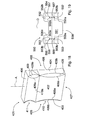
- the packet 201 disclosed until now is preferably made from a flat blank 300, made of cardboard or the like ( figure 13 ).
- This blank 300 has a direction of greatest extent C corresponding to the main direction A of the packet 201 and a substantially rectangular shape.
- the blank 300 comprises a plurality of panels 301 arranged in succession along the direction of greatest extent C of the blank that are each connected to the next one by a transverse weakening line 302, transverse to the direction of greatest extent C.
- These panels 301 define the front wall 202, the rear wall 203, the top wall 206 and the bottom wall 207 of the packet 201.
- the blank 300 comprises a pair of wings 303a, 303b arranged on opposite sides of one or more panels 301, in which each wing 303a, 303b defines an inner or outer face of a lateral wall 204, 205 of the packet 201.
- the blank 300 further comprises a pair of first 304 and second 305 flaps each interposed between a wing 303a, 303b and the respective panel 301.
- Each of the flaps 304, 305, of triangular or trapezoidal shape has a transverse dimension that is variable along the direction of greatest extent C of the blank 300.
- each flap 304, 305 extends, along the direction of greatest extent C, between a first 304a, 305a and a second 304b, 305b weakening line.
- each flap 304, 305, along the direction of greatest extent C is connected to the respective panel 301 by the first weakening line 304a, 305a and to the respective wing 303a, 303b by the second weakening line 304b, 305b.
- the measurement of the distance between the two weakening lines 304a and 304b and between the two weakening lines 305a and 305b of a respective single flap 304, 305 is variable along the direction of greatest extent C.
- the weakening lines 304a, 304b extend from a common vertex v1' positioned at the panel 301 intended for forming the bottom wall 207 of the packet 201, diverging from one another along the direction of greatest extent C moving away from the panel 301 intended for forming the bottom wall 207.
- the weakening lines 305a, 305b adjacent to the panel 301 intended for forming the front wall 202 of the packet 201 extend, spaced apart from one another, starting from a first cutting line 306a of the blank 300 intended for forming an abutment for the lid 211 in the closed position of the packet 201, diverging from one another along the direction of greatest extent C moving away from the first cutting line 306a.
- weakening lines 305a, 305b adjacent to the panel 301 intended for forming an outer front face of the lid 211 extend from a common vertex v2' positioned at the panel 301 intended for forming the top wall 206 of the packet 201, diverging from one another along the direction of greatest extent C moving away from the panel 301 intended for forming the top wall 206.
- the weakening lines 304a, 304b, 305a, 305b define the respective edges 208a, 208b, 209a, 209b of the corner walls 208, 209 of the packet 201.
- each first flap 304 is delimited, transversely with respect to the direction of greatest extent C of the blank 300, by a second cutting line 306b.
- Each second flap 305 positioned on opposite sides of the panel 301 intended for forming the front wall 202 is delimited, transversely with respect to the direction of greatest extent C of the blank 300, by the first cutting line 306a and by a third cutting line 306c.
- each second flap 305 positioned on opposite sides of the panel 301 intended for forming an outer front face of the lid 211 is delimited, transversely with respect to the direction of greatest extent C of the blank 300, by a fourth cutting line 306d.
- the flaps 304, 305 define respective circumscribed surfaces 307, 308 of the blank 300 of triangular or trapezoidal shape.
- the inner frame 242 disclosed above is preferably made from a flat blank 350, made of cardboard or the like ( figure 12 ).
- the blank 350 has an axis of symmetry D corresponding to the main direction A of the packet 201.
- This blank 350 comprises a central panel 351, a pair of flaps 352, 353 arranged on opposite sides of the central panel 351 and a pair of wings 354, 355 that are each connected to a respective flap 352, 353.
- the central panel 351 defines the front wall 242c of the inner frame 242, the flaps 352, 353 define the corner walls 243, 244 of the inner frame 242, whereas the wings 354, 355 define the lateral sides 242a, 242b of the inner frame 242.
- the flaps 352, 353 have a triangular shape and extend, starting from a common vertex v4 positioned at a first cutting line 306e of the blank 350, between a first 352a, 353a, and a second 352b, 353b weakening line.
- the measurement of the distance between the two weakening lines 352a and 352b and between the two weakening lines 353a and 353b of a respective single flap 352, 353 is variable starting from a common vertex along the axis of symmetry D.
- the weakening lines 352a, 352b, 353a, 353b define the respective edges 243a, 243b, 244a, 244b of the corner walls 243, 244 of the inner frame 242.
- the flaps 352, 353 are delimited transversely by a second cutting line 306f of the blank 350.
- the flaps 352, 353 define respective circumscribed surfaces 357, 358 of the blank 350 of triangular shape.
- the method for forming the weakening lines 304a, 304b, 305a, 305b, 352a, 352b, 353a and 353b is substantially similar to what has been disclosed previously with reference to the blank 100 of the container 1.
- a pair of tools U1, U2 is illustrated that is arranged to perform, by drawing, the plastic deforming operation on the blank 300.
- Drawing is performed in the course of a stop of each blank 300 at the forming station F, by the tools U1, U2 comprising a punch U1 and a corresponding counter-punch U2 that cooperate between themselves and are movable with reciprocal motion along a path that is transverse to the advancement line L.
- the tools U1, U2 are arranged on opposite sides of the advancement line L, and at least one of them, in this case the punch U1, has projections 330 that are suitable for making, in cooperation with respective recesses 331 which are present in the counter-punch U2 and are suitable for coupling with the projections 330, the convex portions that are intended to define, with the sides of greatest extent thereof, the weakening lines 304a, 304b, 305a, 305b.
- the projections 330 and the recesses 331 have, in a plan view, the same shape and dimension as the flaps 304, 305 to be deformed plastically.
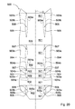
- Drawing is performed in the course of a stop of each blank 350 at a further forming station, which is not shown, by the tools U1', U2' comprising a punch U1' and a corresponding counter-punch U2' that cooperate between themselves and are movable with reciprocal motion along a path that is transverse to a respective advancement line.
- the tools U1', U2' are arranged on opposite sides of the advancement line, and at least one thereof, in particular the punch U1', has projections 330' that are suitable for making, in cooperation with respective recesses 331' which are present in the counter-punch U2' and are suitable for coupling with the projections 330', the convex portions intended to define, with the sides of maximum extent thereof, the weakening lines 352a, 352b, 353a and 353b.
- the projections 330' and the recesses 331' have, in a plan view, the same shape and dimension as the flaps 352, 353 to be deformed plastically.
- the counter-punches U2, U2' are made of resilient material, so as to constitute a yielding contrasting element with respect to the projections 330, 330' of the punch U1, U1', with consequent formation of the convex portions in each blank 300, 350.
- the blanks 300, 350 are fed continuously and the plastic deforming operation is achieved by drawing from respective pairs of rollers that counter-rotate and cooperate with one another.
- the rollers have axes that are transverse to the respective advancement lines of the blanks 300, 350 and are arranged on opposite sides of the advancement lines.
- At least one of the rollers of each pair of rollers in this case the respective upper rollers, have on the cylindrical surfaces thereof, projections that are suitable for making, in cooperation with respective recesses that are present on the cylindrical surfaces of the lower rollers and are suitable for coupling with the projections of the upper rollers, the convex portions intended to define, with their sides of maximum extent, the weakening lines 304a, 304b, 305a, 305b, 352a, 352b, 353a and 353b of the blanks 300, 350.
- the lower rollers are made of resilient material, so as to constitute a yielding contrasting element with respect to the projections of the upper rollers, with consequent formation of convex portions in each blank 300, 350.
- the blanks 300, 350 constitute parts of respective strips defined by a succession of blanks joined together and arranged with their longitudinal axes parallel to the feed lines of the strip.
- the method disclosed above can be advantageously used to make weakening lines 504a, 504b, 505a and 505b of a blank 500 and weakening lines 552a, 552b, 553a and 553b of a blank 550 intended to form, after folding, a packet 401 of the type illustrated in figure 18 .
- the packet 401 is of rigid type, extends according to a substantially parallelpipedon structure around a main direction A and has inside a compartment, which is not shown, intended for housing a group of cigarettes, which are not shown.
- the main direction A is the direction along which the packet 401 prevalently extends.
- the packet 401 comprises a front wall 402, a rear wall 403 facing the front wall 402, a pair of lateral sides 404, 405, a top wall 406 and a bottom wall 407.
- the front wall 402 is substantially flat and extends parallel to the rear wall 403, whereas the two lateral sides 404, 505 (parallel to one another) are transverse thereto.
- the top 406 and bottom 407 walls are (at least in a closed configuration of the packet 401) orthogonal to the main direction A and have a plurality of sides from which the front wall 402 and rear wall 403 and the lateral sides 404, 405 extend.
- the packet 401 comprises at least one first corner wall 408 and at least one second corner wall 409, each interposed between a lateral side 404, 405 and the respective front wall 402 or rear wall 403.
- the first corner wall 408 and the second corner wall 409 have a transverse dimension that is variable along the main direction A of the packet 401.
- each corner wall 408, 409 has at least one portion of lenticular shape that is concave towards the inside of the packet 401.
- each corner wall 408, 409 has at least one portion of lenticular shape that is convex towards the outside of the packet 401.
- the corner wall 408 extends between two curved arched edges, not shown, each connected respectively to the rear wall 403 and to one of the lateral sides 404, 405.
- the corner wall 409 extends between two curved arched edges 409a, 409b, each connected respectively to the front wall 402 and to one of the lateral sides 404, 405.
- edges extend by diverging starting from a first common vertex and converging on a second common vertex.
- the corner walls 408, 409 comprise a plurality of consecutive portions of lenticular shape
- the respective curvilinear edges converge on at least one tangent intermediate point positioned in an intermediate zone between the first and the second common vertex.
- the packet 401 comprises a pair of first corner walls 408 and a pair of second corner walls 409.
- the packet 401 has four corner walls 408, 409, which in substance totally replace the sharp edge at right angles of the normal packets.
- the illustrated embodiment relates to a rigid packet for smoke articles of the hinged lid type.
- the packet 401 in figure 18 comprises a box body 410 provided with a top edge 410a defining an access mouth, which is not shown, to the compartment containing the smoke articles, and a lid 411 hinged to the box body 410 at the top edge 410a. More precisely, the lid 411 is hinged along the top edge 410a at the rear wall 403. In this manner, the lid 411 can freely rotate with respect to the box body 410 between a closed position of the access mouth and an open position of the access mouth.
- first 408 and second 409 corner walls extend partially on the box body 410 and partially on the lid 411.
- the box body 410 extends along the main direction A and comprises a front face defining part of the front wall 402, a rear face defining part of the rear wall 403, a pair of lateral faces defining part of the lateral sides 404, 405 and a bottom face defining the bottom wall 407 of the packet 401.
- the lid 411 comprises a front face defining part of the front wall 402, a rear face defining part of the rear wall 403, a pair of lateral faces defining part of the lateral sides 404, 405 and a top face defining the top wall 406 of the packet 401.
- the packet 401 also comprises an inner frame, which is not shown, connected to the top edge 410a of the box body 410 so as to protrude from the access mouth.
- This inner frame is substantially "U”-shaped so as to define a central cut for removing smoke articles (cigarettes).
- the inner frame has two lateral sides and a front wall having a cut top edge so as to define the "U" conformation.
- the inner frame comprises two corner walls that are counter-shaped with respect to the second corner walls 409.
- Each portion of corner wall of the inner frame that protrudes from the access mouth is intended to engage with a corresponding portion of corner wall 409 arranged at the lid 411 when the lid 411 is in the closed position.
- the inner face of the corner walls 409 arranged at the lid 411 joins the outer face of the corner walls of the inner frame to prevent the involuntary opening of the packet 401.
- the corner walls of the inner frame are cut, i.e. are deprived of the common vertex by the side of the access mouth.
- the packet 401 disclosed until now is preferably made from a flat blank 500, made of cardboard or the like ( figure 20 ).
- This blank 500 has a direction of greatest extent C corresponding to the main direction A of the packet 401 and a substantially rectangular shape.
- the blank 500 comprises a plurality of panels 501 arranged in succession along the direction of greatest extent C of the blank that are each connected to the next one by a transverse weakening line 502, transverse with respect to the direction of greatest extent C.
- These panels 501 define the front wall 402, the rear wall 403, the top wall 406 and the bottom wall 407 of the packet 401.
- the blank 500 comprises a pair of wings 503a, 503b arranged on opposite sides of one or more panels 501, in which each wing 503a, 503b defines an inner or outer face of a lateral wall 404, 405 of the packet 401.
- the blank 500 further comprises a pair of first 504 and second 505 flaps each interposed between a wing 503a, 503b and the respective panel 501.
- Each of the flaps 504, 505, of lenticular shape has a transverse dimension that is variable along the direction of greatest extent C of the blank 500.
- each flap 504, 505 extends, along the direction of greatest extent C, between a first 504a, 505a and a second weakening line 504b, 505b which, once they are folded, define the corner walls 408, 409.
- the weakening lines 504a, 504b, 505a, 505b extend diverging, starting from a first common vertex and converging on a second common vertex.
- each flap 504, 505, along the direction of greatest extent C is connected to the respective panel 501 by the first weakening line 504a, 505a and to the respective wing 503a, 503b by the second weakening line 504b, 505b.
- the weakening lines 504a, 504b, 505a, 505b extend along a direction that is tilted with respect to the direction C by an angle comprised between 10 and 30 degrees.
- the weakening lines 504a, 504b, 505a, 505b create a substantially lenticular shape.
- the measurement of the distance between the two weakening lines 504a and 504b and between the two weakening lines 505a and 505b of a respective single flap 504, 505 is variable along the direction of greatest extent C.
- the weakening lines 504a, 504b, 505a, 505b define the respective edges of the corner walls 408, 409 of the packet 401.
- the flaps 504, 505 define respective circumscribed surfaces 507, 508 of lenticular shape.
- the inner frame disclosed above is preferably made from a flat blank 550, made of cardboard or the like ( figure 19 ).
- the blank 550 has an axis of symmetry D corresponding to the main direction A of the packet 401.
- This blank 550 comprises a central panel 551, a pair of flaps 552, 553 arranged on opposite sides of the central panel 551 and a pair of wings 554, 555 that are each connected to a respective flap 552, 553.
- the central panel 551 defines the front wall of the inner frame
- the flaps 552, 553 define the corner walls of the inner frame
- the wings 554, 555 define the lateral sides of the inner frame.
- the flaps 552, 553 extend between a first 552a, 553a, and a second 552b, 553b weakening line that have a curvilinear shape.
- the weakening lines 552a, 552b, 553a, 553b define the respective edges of the corner walls of the inner frame.
- the flaps 552, 553 are delimited transversely by cutting lines 506e and 506f of the blank 550.
- the flaps 552, 553 define respective circumscribed surfaces 557, 558 of the blank 550.
- the method for forming the weakening lines 504a, 504b, 505a, 505b, 552a, 552b, 553a and 553b is substantially similar to that disclosed with reference to the container 1 and to the packet 201, except for the shape of the projections and of the recesses.
- Drawing is performed in the course of a stop of each blank 500 at the forming station F, by the tools U1, U2 comprising a punch U1 and a corresponding counter-punch U2 that cooperate between themselves and are movable with reciprocal motion along a path that is transverse to the advancement line L.
- the tools U1, U2 are arranged on opposite sides of the advancement line L, and at least one thereof, in particular the punch U1, has projections 530 that are suitable for making, in cooperation with respective recesses 531 which are present in the die U2 and suitable for coupling with the projections 530, convex portions intended to define, with their sides of maximum extent, the weakening lines 504a, 504b,505a,505b.
- the projections 530 and the recesses 531 have, in a plan view, the same shape and dimension as the flaps 504, 505 to be deformed plastically.
- Drawing is performed in the course of a stop of each blank 550 at a further forming station, which is not shown, by the tools U1', U2' comprising a punch U1' and a corresponding counter-punch U2' that cooperate between themselves and are movable with reciprocal motion along a path that is transverse to a respective advancement line.
- the tools U1', U2' are arranged on opposite sides of the advancement line, and at least one thereof, in particular the punch U1', has projections 530' that are suitable for making, in cooperation with respective recesses 531' which are present in the die U2' and suitable for coupling with the projections 530', the convex portions intended to define, with their sides of maximum extent, the weakening lines 552a, 552b, 553a and 553b.
- the projections 530' and the recesses 531' have, in a plan view, the same shape and dimension as the flaps 552, 553 to be deformed plastically.
- the counter-punches U2, U2' are made of resilient material, so as to constitute a yielding contrasting element with respect to the projections 530, 530' of the punch U1, U1', with consequent formation of convex portions in each blank 500, 550.
- the blanks 500, 550 are fed continuously and the plastic deforming operation is achieved by drawing respective pairs of rollers that counter-rotate and cooperate between themselves.
- the rollers have axes that are transverse with respect to the respective advancement lines of the blanks 500, 550 and are arranged on opposite sides of the advancement lines.
- At least one of the rollers of each pair of rollers in this case the respective upper rollers, have on their cylindrical surfaces projections suitable for making, in cooperation with respective recesses that are made on the cylindrical surfaces of the lower rollers and are suitable for coupling with the projections of the upper rollers, the convex portions intended to define, with their sides of maximum extent, the weakening lines 504a, 504b, 505a, 505b, 552a, 552b, 553a and 553b of the blanks 500, 550.
- the lower rollers are made of resilient material, so as to constitute a yielding contrasting element with respect to the projections of the upper rollers, with consequent formation of the convex portions in each blank 500, 550.
- the blanks 500, 550 constitute parts of respective strips defined by a succession of blanks joined together and arranged with the longitudinal axes thereof parallel to the feed lines of the strip.
Landscapes
- Engineering & Computer Science (AREA)
- Mechanical Engineering (AREA)
- Cartons (AREA)
- Auxiliary Devices For And Details Of Packaging Control (AREA)
- Containers Having Bodies Formed In One Piece (AREA)
- Blow-Moulding Or Thermoforming Of Plastics Or The Like (AREA)
Priority Applications (1)
| Application Number | Priority Date | Filing Date | Title |
|---|---|---|---|
| PL15153292T PL2902184T3 (pl) | 2014-02-03 | 2015-01-30 | Sposób tworzenia linii o zmniejszonej wytrzymałości w wykroju przeznaczonym do utworzenia opakowania |
Applications Claiming Priority (1)
| Application Number | Priority Date | Filing Date | Title |
|---|---|---|---|
| ITBO20140045 | 2014-02-03 |
Publications (2)
| Publication Number | Publication Date |
|---|---|
| EP2902184A1 true EP2902184A1 (fr) | 2015-08-05 |
| EP2902184B1 EP2902184B1 (fr) | 2016-10-12 |
Family
ID=50349691
Family Applications (1)
| Application Number | Title | Priority Date | Filing Date |
|---|---|---|---|
| EP15153292.6A Not-in-force EP2902184B1 (fr) | 2014-02-03 | 2015-01-30 | Procédé pour réaliser des lignes d'affaiblissement sur un découpe pour une boîte pliante |
Country Status (3)
| Country | Link |
|---|---|
| EP (1) | EP2902184B1 (fr) |
| PL (1) | PL2902184T3 (fr) |
| RU (1) | RU2015103064A (fr) |
Cited By (2)
| Publication number | Priority date | Publication date | Assignee | Title |
|---|---|---|---|---|
| DE102018005838A1 (de) * | 2018-07-25 | 2020-01-30 | Focke & Co. (Gmbh & Co. Kg) | Verfahren und Vorrichtung zum Handhaben von Zuschnitten aus Verpackungsmaterial |
| EP3718915A1 (fr) * | 2019-04-02 | 2020-10-07 | Tetra Laval Holdings & Finance S.A. | Outil de pli et système et procédé de pliage d'un matériau d'emballage |
Citations (4)
| Publication number | Priority date | Publication date | Assignee | Title |
|---|---|---|---|---|
| US5064409A (en) * | 1989-02-21 | 1991-11-12 | Philip Morris Incorporated | Method and apparatus for forming containers with rounded edges |
| WO1999037576A2 (fr) * | 1998-01-27 | 1999-07-29 | Madern Graveerindustrie En Gereedschappenfabriek B.V. | Installation de cylindres comportant de multiples cannelures |
| DE102010027140A1 (de) * | 2010-07-14 | 2012-01-19 | British American Tobacco (Germany) Gmbh | Zigarettenpackung mit teilweise abgeschrägten Kanten |
| DE202013100205U1 (de) * | 2013-01-15 | 2013-01-25 | Mayr-Melnhof Karton Ag | Vorrichtung zum zumindest teilweisen Aufprägen eines oder mehrerer haptischer Muster auf eine Materialbahn, einen Materialbogen oder einen Zuschnitt aus Karton |
-
2015
- 2015-01-30 EP EP15153292.6A patent/EP2902184B1/fr not_active Not-in-force
- 2015-01-30 PL PL15153292T patent/PL2902184T3/pl unknown
- 2015-02-02 RU RU2015103064A patent/RU2015103064A/ru not_active Application Discontinuation
Patent Citations (5)
| Publication number | Priority date | Publication date | Assignee | Title |
|---|---|---|---|---|
| US5064409A (en) * | 1989-02-21 | 1991-11-12 | Philip Morris Incorporated | Method and apparatus for forming containers with rounded edges |
| WO1999037576A2 (fr) * | 1998-01-27 | 1999-07-29 | Madern Graveerindustrie En Gereedschappenfabriek B.V. | Installation de cylindres comportant de multiples cannelures |
| DE102010027140A1 (de) * | 2010-07-14 | 2012-01-19 | British American Tobacco (Germany) Gmbh | Zigarettenpackung mit teilweise abgeschrägten Kanten |
| WO2012007302A1 (fr) | 2010-07-14 | 2012-01-19 | British American Tobacco (Germany) Gmbh | Paquet de cigarettes muni d'arêtes partiellement biseautées |
| DE202013100205U1 (de) * | 2013-01-15 | 2013-01-25 | Mayr-Melnhof Karton Ag | Vorrichtung zum zumindest teilweisen Aufprägen eines oder mehrerer haptischer Muster auf eine Materialbahn, einen Materialbogen oder einen Zuschnitt aus Karton |
Cited By (2)
| Publication number | Priority date | Publication date | Assignee | Title |
|---|---|---|---|---|
| DE102018005838A1 (de) * | 2018-07-25 | 2020-01-30 | Focke & Co. (Gmbh & Co. Kg) | Verfahren und Vorrichtung zum Handhaben von Zuschnitten aus Verpackungsmaterial |
| EP3718915A1 (fr) * | 2019-04-02 | 2020-10-07 | Tetra Laval Holdings & Finance S.A. | Outil de pli et système et procédé de pliage d'un matériau d'emballage |
Also Published As
| Publication number | Publication date |
|---|---|
| RU2015103064A3 (fr) | 2018-07-19 |
| PL2902184T3 (pl) | 2017-07-31 |
| EP2902184B1 (fr) | 2016-10-12 |
| RU2015103064A (ru) | 2016-08-20 |
Similar Documents
| Publication | Publication Date | Title |
|---|---|---|
| JP5361284B2 (ja) | 包装ホイルの取り扱いのためのデバイス | |
| US7438182B2 (en) | Blank and a relative packet of cigarettes | |
| EP2864221B1 (fr) | Paquet pour produits de tabac et découpe plate pour fabriquer le paquet | |
| AU2007216342B2 (en) | Curved cigarette pack flap formation on curved surfaces | |
| US3039372A (en) | Creasing apparatus, method and product | |
| US20060283732A1 (en) | Container blank for a box with hinged lid | |
| WO2012123189A1 (fr) | Emballage ayant un bord arrondi | |
| EP2815877A1 (fr) | Appareil et procédé de production d'ébauches d'emballage | |
| EP2902184B1 (fr) | Procédé pour réaliser des lignes d'affaiblissement sur un découpe pour une boîte pliante | |
| JP2015518454A (ja) | シガレットパッケージおよびその製造方法 | |
| US6220430B1 (en) | Rigid wrapper with hinged lid for tobacco products | |
| EP1335867B1 (fr) | Paquet de cigarette a couvercle articule | |
| DE19957058A1 (de) | Verfahren und Vorrichtung zum Herstellen von Kragen für Klappschachteln | |
| CA2754987A1 (fr) | Paquet pour cigarettes | |
| EP1503948B1 (fr) | Conteneur pour articles de tabac et procede de production relatif | |
| KR102033111B1 (ko) | 블랭크 및 그로부터 제조된 3-차원 구조물 | |
| US5066270A (en) | Apparatus for forming innerframe for cigarette pack with rounded corners | |
| US390442A (en) | Paper-box-making machinery | |
| CN103889842A (zh) | 用于制造香烟包装元件的方法和设备 | |
| RU2661844C2 (ru) | Способ и устройство для изготовления заготовок внутренних рамок для пачек сигарет | |
| US20070187472A1 (en) | Hinge-lid container and blank | |
| EP2093152B1 (fr) | Récipients tridimensionnels équipés de décorations en relief et procédé de production de ces récipients | |
| CA2319156A1 (fr) | Installation de cylindres comportant de multiples cannelures | |
| WO2022122695A1 (fr) | Procédé et dispositif de fabrication de flans pour des rebords de paquets pour cigarettes | |
| EP0895851B1 (fr) | Procédé et dispositif pour la fabrication de boîtes rigide avec couvercle articulé |
Legal Events
| Date | Code | Title | Description |
|---|---|---|---|
| PUAI | Public reference made under article 153(3) epc to a published international application that has entered the european phase |
Free format text: ORIGINAL CODE: 0009012 |
|
| 17P | Request for examination filed |
Effective date: 20150130 |
|
| AK | Designated contracting states |
Kind code of ref document: A1 Designated state(s): AL AT BE BG CH CY CZ DE DK EE ES FI FR GB GR HR HU IE IS IT LI LT LU LV MC MK MT NL NO PL PT RO RS SE SI SK SM TR |
|
| AX | Request for extension of the european patent |
Extension state: BA ME |
|
| 17P | Request for examination filed |
Effective date: 20160205 |
|
| RBV | Designated contracting states (corrected) |
Designated state(s): AL AT BE BG CH CY CZ DE DK EE ES FI FR GB GR HR HU IE IS IT LI LT LU LV MC MK MT NL NO PL PT RO RS SE SI SK SM TR |
|
| GRAP | Despatch of communication of intention to grant a patent |
Free format text: ORIGINAL CODE: EPIDOSNIGR1 |
|
| RIC1 | Information provided on ipc code assigned before grant |
Ipc: B65B 19/22 20060101ALI20160331BHEP Ipc: B31B 1/25 20060101ALI20160331BHEP Ipc: B31F 1/07 20060101ALI20160331BHEP Ipc: B31F 1/08 20060101AFI20160331BHEP |
|
| INTG | Intention to grant announced |
Effective date: 20160503 |
|
| GRAS | Grant fee paid |
Free format text: ORIGINAL CODE: EPIDOSNIGR3 |
|
| GRAA | (expected) grant |
Free format text: ORIGINAL CODE: 0009210 |
|
| AK | Designated contracting states |
Kind code of ref document: B1 Designated state(s): AL AT BE BG CH CY CZ DE DK EE ES FI FR GB GR HR HU IE IS IT LI LT LU LV MC MK MT NL NO PL PT RO RS SE SI SK SM TR |
|
| REG | Reference to a national code |
Ref country code: GB Ref legal event code: FG4D |
|
| REG | Reference to a national code |
Ref country code: CH Ref legal event code: EP |
|
| REG | Reference to a national code |
Ref country code: AT Ref legal event code: REF Ref document number: 836122 Country of ref document: AT Kind code of ref document: T Effective date: 20161015 |
|
| REG | Reference to a national code |
Ref country code: CH Ref legal event code: NV Representative=s name: FIAMMENGHI-FIAMMENGHI, CH |
|
| REG | Reference to a national code |
Ref country code: IE Ref legal event code: FG4D |
|
| REG | Reference to a national code |
Ref country code: DE Ref legal event code: R096 Ref document number: 602015000447 Country of ref document: DE |
|
| REG | Reference to a national code |
Ref country code: LT Ref legal event code: MG4D |
|
| REG | Reference to a national code |
Ref country code: NL Ref legal event code: MP Effective date: 20161012 |
|
| PG25 | Lapsed in a contracting state [announced via postgrant information from national office to epo] |
Ref country code: LV Free format text: LAPSE BECAUSE OF FAILURE TO SUBMIT A TRANSLATION OF THE DESCRIPTION OR TO PAY THE FEE WITHIN THE PRESCRIBED TIME-LIMIT Effective date: 20161012 |
|
| REG | Reference to a national code |
Ref country code: AT Ref legal event code: MK05 Ref document number: 836122 Country of ref document: AT Kind code of ref document: T Effective date: 20161012 |
|
| PG25 | Lapsed in a contracting state [announced via postgrant information from national office to epo] |
Ref country code: NO Free format text: LAPSE BECAUSE OF FAILURE TO SUBMIT A TRANSLATION OF THE DESCRIPTION OR TO PAY THE FEE WITHIN THE PRESCRIBED TIME-LIMIT Effective date: 20170112 Ref country code: SE Free format text: LAPSE BECAUSE OF FAILURE TO SUBMIT A TRANSLATION OF THE DESCRIPTION OR TO PAY THE FEE WITHIN THE PRESCRIBED TIME-LIMIT Effective date: 20161012 Ref country code: GR Free format text: LAPSE BECAUSE OF FAILURE TO SUBMIT A TRANSLATION OF THE DESCRIPTION OR TO PAY THE FEE WITHIN THE PRESCRIBED TIME-LIMIT Effective date: 20170113 Ref country code: LT Free format text: LAPSE BECAUSE OF FAILURE TO SUBMIT A TRANSLATION OF THE DESCRIPTION OR TO PAY THE FEE WITHIN THE PRESCRIBED TIME-LIMIT Effective date: 20161012 |
|
| PG25 | Lapsed in a contracting state [announced via postgrant information from national office to epo] |
Ref country code: NL Free format text: LAPSE BECAUSE OF FAILURE TO SUBMIT A TRANSLATION OF THE DESCRIPTION OR TO PAY THE FEE WITHIN THE PRESCRIBED TIME-LIMIT Effective date: 20161012 Ref country code: HR Free format text: LAPSE BECAUSE OF FAILURE TO SUBMIT A TRANSLATION OF THE DESCRIPTION OR TO PAY THE FEE WITHIN THE PRESCRIBED TIME-LIMIT Effective date: 20161012 Ref country code: BE Free format text: LAPSE BECAUSE OF FAILURE TO SUBMIT A TRANSLATION OF THE DESCRIPTION OR TO PAY THE FEE WITHIN THE PRESCRIBED TIME-LIMIT Effective date: 20161012 Ref country code: ES Free format text: LAPSE BECAUSE OF FAILURE TO SUBMIT A TRANSLATION OF THE DESCRIPTION OR TO PAY THE FEE WITHIN THE PRESCRIBED TIME-LIMIT Effective date: 20161012 Ref country code: IS Free format text: LAPSE BECAUSE OF FAILURE TO SUBMIT A TRANSLATION OF THE DESCRIPTION OR TO PAY THE FEE WITHIN THE PRESCRIBED TIME-LIMIT Effective date: 20170212 Ref country code: AT Free format text: LAPSE BECAUSE OF FAILURE TO SUBMIT A TRANSLATION OF THE DESCRIPTION OR TO PAY THE FEE WITHIN THE PRESCRIBED TIME-LIMIT Effective date: 20161012 Ref country code: RS Free format text: LAPSE BECAUSE OF FAILURE TO SUBMIT A TRANSLATION OF THE DESCRIPTION OR TO PAY THE FEE WITHIN THE PRESCRIBED TIME-LIMIT Effective date: 20161012 Ref country code: PT Free format text: LAPSE BECAUSE OF FAILURE TO SUBMIT A TRANSLATION OF THE DESCRIPTION OR TO PAY THE FEE WITHIN THE PRESCRIBED TIME-LIMIT Effective date: 20170213 Ref country code: FI Free format text: LAPSE BECAUSE OF FAILURE TO SUBMIT A TRANSLATION OF THE DESCRIPTION OR TO PAY THE FEE WITHIN THE PRESCRIBED TIME-LIMIT Effective date: 20161012 |
|
| PGFP | Annual fee paid to national office [announced via postgrant information from national office to epo] |
Ref country code: TR Payment date: 20170111 Year of fee payment: 3 |
|
| REG | Reference to a national code |
Ref country code: DE Ref legal event code: R097 Ref document number: 602015000447 Country of ref document: DE |
|
| PG25 | Lapsed in a contracting state [announced via postgrant information from national office to epo] |
Ref country code: CZ Free format text: LAPSE BECAUSE OF FAILURE TO SUBMIT A TRANSLATION OF THE DESCRIPTION OR TO PAY THE FEE WITHIN THE PRESCRIBED TIME-LIMIT Effective date: 20161012 Ref country code: RO Free format text: LAPSE BECAUSE OF FAILURE TO SUBMIT A TRANSLATION OF THE DESCRIPTION OR TO PAY THE FEE WITHIN THE PRESCRIBED TIME-LIMIT Effective date: 20161012 Ref country code: SK Free format text: LAPSE BECAUSE OF FAILURE TO SUBMIT A TRANSLATION OF THE DESCRIPTION OR TO PAY THE FEE WITHIN THE PRESCRIBED TIME-LIMIT Effective date: 20161012 Ref country code: DK Free format text: LAPSE BECAUSE OF FAILURE TO SUBMIT A TRANSLATION OF THE DESCRIPTION OR TO PAY THE FEE WITHIN THE PRESCRIBED TIME-LIMIT Effective date: 20161012 Ref country code: EE Free format text: LAPSE BECAUSE OF FAILURE TO SUBMIT A TRANSLATION OF THE DESCRIPTION OR TO PAY THE FEE WITHIN THE PRESCRIBED TIME-LIMIT Effective date: 20161012 |
|
| PLBE | No opposition filed within time limit |
Free format text: ORIGINAL CODE: 0009261 |
|
| STAA | Information on the status of an ep patent application or granted ep patent |
Free format text: STATUS: NO OPPOSITION FILED WITHIN TIME LIMIT |
|
| PG25 | Lapsed in a contracting state [announced via postgrant information from national office to epo] |
Ref country code: SM Free format text: LAPSE BECAUSE OF FAILURE TO SUBMIT A TRANSLATION OF THE DESCRIPTION OR TO PAY THE FEE WITHIN THE PRESCRIBED TIME-LIMIT Effective date: 20161012 Ref country code: BG Free format text: LAPSE BECAUSE OF FAILURE TO SUBMIT A TRANSLATION OF THE DESCRIPTION OR TO PAY THE FEE WITHIN THE PRESCRIBED TIME-LIMIT Effective date: 20170112 Ref country code: IT Free format text: LAPSE BECAUSE OF FAILURE TO SUBMIT A TRANSLATION OF THE DESCRIPTION OR TO PAY THE FEE WITHIN THE PRESCRIBED TIME-LIMIT Effective date: 20161012 |
|
| PGFP | Annual fee paid to national office [announced via postgrant information from national office to epo] |
Ref country code: PL Payment date: 20170104 Year of fee payment: 3 |
|
| 26N | No opposition filed |
Effective date: 20170713 |
|
| PG25 | Lapsed in a contracting state [announced via postgrant information from national office to epo] |
Ref country code: MC Free format text: LAPSE BECAUSE OF FAILURE TO SUBMIT A TRANSLATION OF THE DESCRIPTION OR TO PAY THE FEE WITHIN THE PRESCRIBED TIME-LIMIT Effective date: 20161012 |
|
| REG | Reference to a national code |
Ref country code: FR Ref legal event code: ST Effective date: 20170929 |
|
| PG25 | Lapsed in a contracting state [announced via postgrant information from national office to epo] |
Ref country code: FR Free format text: LAPSE BECAUSE OF NON-PAYMENT OF DUE FEES Effective date: 20170131 |
|
| REG | Reference to a national code |
Ref country code: IE Ref legal event code: MM4A |
|
| PG25 | Lapsed in a contracting state [announced via postgrant information from national office to epo] |
Ref country code: SI Free format text: LAPSE BECAUSE OF FAILURE TO SUBMIT A TRANSLATION OF THE DESCRIPTION OR TO PAY THE FEE WITHIN THE PRESCRIBED TIME-LIMIT Effective date: 20161012 Ref country code: LU Free format text: LAPSE BECAUSE OF NON-PAYMENT OF DUE FEES Effective date: 20170130 |
|
| PG25 | Lapsed in a contracting state [announced via postgrant information from national office to epo] |
Ref country code: IE Free format text: LAPSE BECAUSE OF NON-PAYMENT OF DUE FEES Effective date: 20170130 |
|
| PG25 | Lapsed in a contracting state [announced via postgrant information from national office to epo] |
Ref country code: MT Free format text: LAPSE BECAUSE OF NON-PAYMENT OF DUE FEES Effective date: 20170130 |
|
| PG25 | Lapsed in a contracting state [announced via postgrant information from national office to epo] |
Ref country code: HU Free format text: LAPSE BECAUSE OF FAILURE TO SUBMIT A TRANSLATION OF THE DESCRIPTION OR TO PAY THE FEE WITHIN THE PRESCRIBED TIME-LIMIT; INVALID AB INITIO Effective date: 20150130 |
|
| GBPC | Gb: european patent ceased through non-payment of renewal fee |
Effective date: 20190130 |
|
| PG25 | Lapsed in a contracting state [announced via postgrant information from national office to epo] |
Ref country code: CY Free format text: LAPSE BECAUSE OF FAILURE TO SUBMIT A TRANSLATION OF THE DESCRIPTION OR TO PAY THE FEE WITHIN THE PRESCRIBED TIME-LIMIT Effective date: 20161012 |
|
| PG25 | Lapsed in a contracting state [announced via postgrant information from national office to epo] |
Ref country code: PL Free format text: LAPSE BECAUSE OF NON-PAYMENT OF DUE FEES Effective date: 20180130 Ref country code: MK Free format text: LAPSE BECAUSE OF FAILURE TO SUBMIT A TRANSLATION OF THE DESCRIPTION OR TO PAY THE FEE WITHIN THE PRESCRIBED TIME-LIMIT Effective date: 20161012 |
|
| PG25 | Lapsed in a contracting state [announced via postgrant information from national office to epo] |
Ref country code: GB Free format text: LAPSE BECAUSE OF NON-PAYMENT OF DUE FEES Effective date: 20190130 |
|
| PGFP | Annual fee paid to national office [announced via postgrant information from national office to epo] |
Ref country code: DE Payment date: 20200129 Year of fee payment: 6 |
|
| PGFP | Annual fee paid to national office [announced via postgrant information from national office to epo] |
Ref country code: CH Payment date: 20200131 Year of fee payment: 6 |
|
| PG25 | Lapsed in a contracting state [announced via postgrant information from national office to epo] |
Ref country code: AL Free format text: LAPSE BECAUSE OF FAILURE TO SUBMIT A TRANSLATION OF THE DESCRIPTION OR TO PAY THE FEE WITHIN THE PRESCRIBED TIME-LIMIT Effective date: 20161012 |
|
| REG | Reference to a national code |
Ref country code: DE Ref legal event code: R119 Ref document number: 602015000447 Country of ref document: DE |
|
| REG | Reference to a national code |
Ref country code: CH Ref legal event code: PL |
|
| PG25 | Lapsed in a contracting state [announced via postgrant information from national office to epo] |
Ref country code: CH Free format text: LAPSE BECAUSE OF NON-PAYMENT OF DUE FEES Effective date: 20210131 Ref country code: DE Free format text: LAPSE BECAUSE OF NON-PAYMENT OF DUE FEES Effective date: 20210803 Ref country code: LI Free format text: LAPSE BECAUSE OF NON-PAYMENT OF DUE FEES Effective date: 20210131 |
|
| PG25 | Lapsed in a contracting state [announced via postgrant information from national office to epo] |
Ref country code: TR Free format text: LAPSE BECAUSE OF NON-PAYMENT OF DUE FEES Effective date: 20180130 |