EP2902220A1 - Kompakte Dämpfer-Feder-Anordnung für Hinterradaufhängung - Google Patents
Kompakte Dämpfer-Feder-Anordnung für Hinterradaufhängung Download PDFInfo
- Publication number
- EP2902220A1 EP2902220A1 EP14193265.7A EP14193265A EP2902220A1 EP 2902220 A1 EP2902220 A1 EP 2902220A1 EP 14193265 A EP14193265 A EP 14193265A EP 2902220 A1 EP2902220 A1 EP 2902220A1
- Authority
- EP
- European Patent Office
- Prior art keywords
- damper
- spring
- support member
- wheel
- mounting platform
- Prior art date
- Legal status (The legal status is an assumption and is not a legal conclusion. Google has not performed a legal analysis and makes no representation as to the accuracy of the status listed.)
- Withdrawn
Links
- 239000000725 suspension Substances 0.000 title claims abstract description 42
- 230000008878 coupling Effects 0.000 description 17
- 238000010168 coupling process Methods 0.000 description 17
- 238000005859 coupling reaction Methods 0.000 description 17
- 239000000463 material Substances 0.000 description 2
- 238000000926 separation method Methods 0.000 description 2
- 241001247986 Calotropis procera Species 0.000 description 1
- 230000000712 assembly Effects 0.000 description 1
- 238000000429 assembly Methods 0.000 description 1
- 238000013016 damping Methods 0.000 description 1
- 238000000034 method Methods 0.000 description 1
Images





Classifications
-
- B—PERFORMING OPERATIONS; TRANSPORTING
- B60—VEHICLES IN GENERAL
- B60G—VEHICLE SUSPENSION ARRANGEMENTS
- B60G7/00—Pivoted suspension arms; Accessories thereof
- B60G7/008—Attaching arms to unsprung part of vehicle
-
- B—PERFORMING OPERATIONS; TRANSPORTING
- B60—VEHICLES IN GENERAL
- B60G—VEHICLE SUSPENSION ARRANGEMENTS
- B60G11/00—Resilient suspensions characterised by arrangement, location or kind of springs
- B60G11/14—Resilient suspensions characterised by arrangement, location or kind of springs having helical, spiral or coil springs only
- B60G11/16—Resilient suspensions characterised by arrangement, location or kind of springs having helical, spiral or coil springs only characterised by means specially adapted for attaching the spring to axle or sprung part of the vehicle
-
- B—PERFORMING OPERATIONS; TRANSPORTING
- B60—VEHICLES IN GENERAL
- B60G—VEHICLE SUSPENSION ARRANGEMENTS
- B60G11/00—Resilient suspensions characterised by arrangement, location or kind of springs
- B60G11/26—Resilient suspensions characterised by arrangement, location or kind of springs having fluid springs only, e.g. hydropneumatic springs
- B60G11/28—Resilient suspensions characterised by arrangement, location or kind of springs having fluid springs only, e.g. hydropneumatic springs characterised by means specially adapted for attaching the spring to axle or sprung part of the vehicle
-
- B—PERFORMING OPERATIONS; TRANSPORTING
- B60—VEHICLES IN GENERAL
- B60G—VEHICLE SUSPENSION ARRANGEMENTS
- B60G13/00—Resilient suspensions characterised by arrangement, location or type of vibration dampers
- B60G13/001—Arrangements for attachment of dampers
- B60G13/003—Arrangements for attachment of dampers characterised by the mounting on the vehicle body or chassis of the damper unit
-
- B—PERFORMING OPERATIONS; TRANSPORTING
- B60—VEHICLES IN GENERAL
- B60G—VEHICLE SUSPENSION ARRANGEMENTS
- B60G13/00—Resilient suspensions characterised by arrangement, location or type of vibration dampers
- B60G13/001—Arrangements for attachment of dampers
- B60G13/005—Arrangements for attachment of dampers characterised by the mounting on the axle or suspension arm of the damper unit
-
- B—PERFORMING OPERATIONS; TRANSPORTING
- B60—VEHICLES IN GENERAL
- B60G—VEHICLE SUSPENSION ARRANGEMENTS
- B60G15/00—Resilient suspensions characterised by arrangement, location or type of combined spring and vibration damper, e.g. telescopic type
- B60G15/02—Resilient suspensions characterised by arrangement, location or type of combined spring and vibration damper, e.g. telescopic type having mechanical spring
- B60G15/06—Resilient suspensions characterised by arrangement, location or type of combined spring and vibration damper, e.g. telescopic type having mechanical spring and fluid damper
- B60G15/07—Resilient suspensions characterised by arrangement, location or type of combined spring and vibration damper, e.g. telescopic type having mechanical spring and fluid damper the damper being connected to the stub axle and the spring being arranged around the damper
-
- B—PERFORMING OPERATIONS; TRANSPORTING
- B60—VEHICLES IN GENERAL
- B60G—VEHICLE SUSPENSION ARRANGEMENTS
- B60G3/00—Resilient suspensions for a single wheel
- B60G3/18—Resilient suspensions for a single wheel with two or more pivoted arms, e.g. parallelogram
- B60G3/20—Resilient suspensions for a single wheel with two or more pivoted arms, e.g. parallelogram all arms being rigid
-
- B—PERFORMING OPERATIONS; TRANSPORTING
- B60—VEHICLES IN GENERAL
- B60G—VEHICLE SUSPENSION ARRANGEMENTS
- B60G2200/00—Indexing codes relating to suspension types
- B60G2200/10—Independent suspensions
- B60G2200/14—Independent suspensions with lateral arms
- B60G2200/144—Independent suspensions with lateral arms with two lateral arms forming a parallelogram
-
- B—PERFORMING OPERATIONS; TRANSPORTING
- B60—VEHICLES IN GENERAL
- B60G—VEHICLE SUSPENSION ARRANGEMENTS
- B60G2204/00—Indexing codes related to suspensions per se or to auxiliary parts
- B60G2204/10—Mounting of suspension elements
- B60G2204/12—Mounting of springs or dampers
-
- B—PERFORMING OPERATIONS; TRANSPORTING
- B60—VEHICLES IN GENERAL
- B60G—VEHICLE SUSPENSION ARRANGEMENTS
- B60G2204/00—Indexing codes related to suspensions per se or to auxiliary parts
- B60G2204/10—Mounting of suspension elements
- B60G2204/12—Mounting of springs or dampers
- B60G2204/124—Mounting of coil springs
-
- B—PERFORMING OPERATIONS; TRANSPORTING
- B60—VEHICLES IN GENERAL
- B60G—VEHICLE SUSPENSION ARRANGEMENTS
- B60G2204/00—Indexing codes related to suspensions per se or to auxiliary parts
- B60G2204/10—Mounting of suspension elements
- B60G2204/12—Mounting of springs or dampers
- B60G2204/124—Mounting of coil springs
- B60G2204/1242—Mounting of coil springs on a damper, e.g. MacPerson strut
-
- B—PERFORMING OPERATIONS; TRANSPORTING
- B60—VEHICLES IN GENERAL
- B60G—VEHICLE SUSPENSION ARRANGEMENTS
- B60G2204/00—Indexing codes related to suspensions per se or to auxiliary parts
- B60G2204/10—Mounting of suspension elements
- B60G2204/12—Mounting of springs or dampers
- B60G2204/124—Mounting of coil springs
- B60G2204/1244—Mounting of coil springs on a suspension arm
-
- B—PERFORMING OPERATIONS; TRANSPORTING
- B60—VEHICLES IN GENERAL
- B60G—VEHICLE SUSPENSION ARRANGEMENTS
- B60G2204/00—Indexing codes related to suspensions per se or to auxiliary parts
- B60G2204/10—Mounting of suspension elements
- B60G2204/12—Mounting of springs or dampers
- B60G2204/126—Mounting of pneumatic springs
-
- B—PERFORMING OPERATIONS; TRANSPORTING
- B60—VEHICLES IN GENERAL
- B60G—VEHICLE SUSPENSION ARRANGEMENTS
- B60G2204/00—Indexing codes related to suspensions per se or to auxiliary parts
- B60G2204/10—Mounting of suspension elements
- B60G2204/12—Mounting of springs or dampers
- B60G2204/126—Mounting of pneumatic springs
- B60G2204/1262—Mounting of pneumatic springs on a damper
-
- B—PERFORMING OPERATIONS; TRANSPORTING
- B60—VEHICLES IN GENERAL
- B60G—VEHICLE SUSPENSION ARRANGEMENTS
- B60G2204/00—Indexing codes related to suspensions per se or to auxiliary parts
- B60G2204/10—Mounting of suspension elements
- B60G2204/12—Mounting of springs or dampers
- B60G2204/128—Damper mount on vehicle body or chassis
-
- B—PERFORMING OPERATIONS; TRANSPORTING
- B60—VEHICLES IN GENERAL
- B60G—VEHICLE SUSPENSION ARRANGEMENTS
- B60G2204/00—Indexing codes related to suspensions per se or to auxiliary parts
- B60G2204/10—Mounting of suspension elements
- B60G2204/12—Mounting of springs or dampers
- B60G2204/129—Damper mount on wheel suspension or knuckle
-
- B—PERFORMING OPERATIONS; TRANSPORTING
- B60—VEHICLES IN GENERAL
- B60G—VEHICLE SUSPENSION ARRANGEMENTS
- B60G2206/00—Indexing codes related to the manufacturing of suspensions: constructional features, the materials used, procedures or tools
- B60G2206/01—Constructional features of suspension elements, e.g. arms, dampers, springs
- B60G2206/50—Constructional features of wheel supports or knuckles, e.g. steering knuckles, spindle attachments
Definitions
- the present invention relates generally to automobiles and, more particularly, to a rear suspension damper-spring assembly.
- the primary considerations for the automobile designer are the design goals set for passenger ride comfort and overall vehicle performance.
- the designer first selects the type of suspension required by the style of vehicle, i.e., high performance car, luxury sedan, compact economy car, SUV, etc., and then configures and adjusts the selected type of suspension to meet the specific design goals set for the vehicle.
- each of which provides specific driving characteristics.
- One common characteristic of each type of suspension is the in-board mounting of the damper and spring assembly regardless of whether or not the damper and spring are coaxially mounted.
- This in-board mounting scheme is illustrated in the torsion beam rear wheel suspension system disclosed in U.S. Patent No. 7,946,600 .
- one end of each arm of a pair of trailing arms is pivotally supported by the vehicle body via a rubber bush joint.
- the other end of each trailing arm extends outward and rearward and supports the corresponding rear wheel via a hub bearing unit.
- the two trailing arms are connected to, and separated by, a torsion beam.
- a spring seat Located between the torsion beam coupling and the hub bearing unit of each trailing arm is a spring seat, thus providing means for resiliently supporting the trailing arm with a coil spring interposed between the spring seat and the vehicle body.
- a damper located behind the coil spring, extends between the corresponding trailing arm and the vehicle body.
- a different type of suspension typically referred to as a multi-link suspension, is disclosed in U.S. Patent No. 6,938,908 .
- each wheel support is connected to the vehicle body using five links.
- a coaxially arranged damper-coil spring assembly is interposed between the vehicle body and an inward projection of the wheel support. When viewed from the side, the damper-coil spring assembly extends in a substantially vertical direction while the assembly, when viewed from the rear, angles slightly inward towards the vehicle's centerline.
- a similar suspension configuration is disclosed in U.S. Patent No. 5,507,510 .
- U.S. Patent No. 6,945,541 Yet another type of suspension, commonly referred to as a double wishbone suspension, is disclosed in U.S. Patent No. 6,945,541 .
- the wheel mount is coupled to upper and lower control arms via ball joints, where each substantially horizontal control arm is approximately parallel to the road surface.
- a coaxial damper-spring assembly is interposed between the wheel mount and the vehicle body and positioned such that it is substantially vertical when viewed from the side, and angled inwards towards the vehicle's centerline when viewed from the rear.
- the damper-spring assembly angles inwardly towards the vehicle's centerline when viewed from the rear of the car.
- the degree to which the assembly intrudes upon either the passenger compartment or the luggage compartment depends both on the angle of the assembly and the mounting location of the assembly relative to the wheel mount.
- the configuration of the assembly for example whether or not the damper and spring are coaxially mounted and where the spring is mounted relative to the damper and wheel mount, also impacts the degree of interior space intrusion. Accordingly, what is needed is a damper-spring assembly that minimizes interior space intrusion while still achieving the desired level of ride comfort and vehicle performance.
- the present invention provides such a damper-spring assembly.
- the wheel suspension system is comprised of (i) a wheel support member that is positioned between the inner and outer tire planes, and preferably in-board of the tire centerline, and that is configured to support a wheel-carrying spindle and that includes a plurality of mounts configured to accept a plurality of rotatably connected linkage arms; (ii) a nonlinearly-shaped damper-spring support member, where the first end of the support member, which may be comprised of a bushing collar, is rotatably connected to the wheel support member and is located between the inner and outer tire planes; (iii) a damper-spring mounting platform, where the second end of the nonlinearly-shaped damper-spring support member is coupled, either rigidly or via a rotatable connection, to the damper-spring mounting platform, and where the nonlinearly-shaped damper-spring support member positions the
- the damper and spring comprising the damper-spring assembly are preferably coaxially mounted and may be configured such that a first bushing collar corresponding to the first end of the nonlinearly-shaped damper-spring support member and a second bushing collar corresponding to the second end of the nonlinearly-shaped damper-spring support member are each positioned on the damper-spring assembly axis.
- the suspension system is configured such that the load path directed along the axis corresponding to the coaxially mounted damper-spring assembly intersects the underlying road surface at the approximate center of the tire contact patch.
- the spring of the damper-spring assembly may rest on the damper-spring mounting platform, and preferably be captured between the damper-spring mounting platform and a spring retaining member, while the damper rod may pass through the spring and be coupled, e.g., bolted, to the damper-spring mounting platform.
- the spring and damper of the damper-spring assembly may be independently mounted to the vehicle body structure.
- the damper-spring assembly may be configured such that the damper is misaligned and offset relative to the spring.
- the spring of the damper-spring assembly may be comprised of an air spring or a coil spring.
- the wheel suspension system is comprised of (i) a wheel support member that is positioned between the inner and outer tire planes, and preferably in-board of the tire centerline, and that is configured to support a wheel-carrying spindle and that includes a plurality of mounts; (ii) a plurality of rotatably connected linkage arms coupled to the plurality of mounts of the wheel support member; (iii) a nonlinearly-shaped damper-spring support member, where the first end of the support member, which may be comprised of a bushing collar, is rotatably connected to a first link, either an upper linkage arm or a lower linkage arm, of the plurality of rotatably connected linkage arms; (iv) a damper-spring mounting platform, where the second end of the nonlinearly-shaped damper-spring support member is coupled, either rigidly or via a rotatable connection, to the damper-spring mounting platform, and where the nonlinearly-shaped damper-spring support member
- the damper and spring comprising the damper-spring assembly are preferably coaxially mounted and may be configured such that a first bushing collar corresponding to the first end of the nonlinearly-shaped damper-spring support member and a second bushing collar corresponding to the second end of the nonlinearly-shaped damper-spring support member are each positioned on the damper-spring assembly axis.
- the suspension system is configured such that the load path directed along the axis corresponding to the coaxially mounted damper-spring assembly intersects the underlying road surface at the approximate center of the tire contact patch.
- the spring of the damper-spring assembly may rest on the damper-spring mounting platform, and preferably be captured between the damper-spring mounting platform and a spring retaining member, while the damper rod may pass through the spring and be coupled, e.g., bolted, to the damper-spring mounting platform.
- the spring and damper of the damper-spring assembly may be independently mounted to the vehicle body structure.
- the damper-spring assembly may be configured such that the damper is misaligned and offset relative to the spring.
- the spring of the damper-spring assembly may be comprised of an air spring or a coil spring.
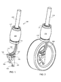
- Figs. 1-3 illustrate a vehicle suspension assembly 100 in accordance with a preferred embodiment of the invention.
- assembly 100 may be utilized in any of a variety of different vehicle suspension types, both front and rear, preferably it is used in a multi-link rear suspension configured to achieve superior ride characteristics while providing increased width in the passenger and/or luggage compartment.
- Figs. 1 and 2 provide a perspective view of damper-spring assembly 100, Fig. 2 including a tire in order to illustrate the location of the assembly relative to the tire.
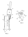
- Fig. 3 provides a front view of damper-spring assembly 100.
- Wheel support member 101 Disposed at the end of assembly 100 is a wheel support member 101.
- Wheel support member 101 is configured to support a wheel-carrying spindle, not shown, and provides multiple mounts for coupling multiple independent linkage arms, i.e., links, that couple the wheel support member to the vehicle body.
- the links, wheel-carrying spindle, wheel and tire are not shown in Fig. 1 , although the tire is shown in Figs. 2 and 3 in order to illustrate the location of the damper-spring assembly 100 relative to the tire.
- member 101 provides five linkage mounts 103-107, each of which allows a corresponding linkage arm to be rotatably coupled to the wheel support member 101.
- wheel support member 101 is located between inner tire plane 303 and outer tire plane 305 of tire 301, and preferably in-board of tire centerline 307, i.e., relative to tire centerline 307 member 101 is located closer to inner tire plane 303 and the vehicle's centerline rather than closer to outer tire plane 305 and the outer envelope of the vehicle.
- Fig. 4 provides a detailed perspective view of wheel support member 101.
- a nonlinearly-shaped damper-spring support member 109 Coupled to wheel support member 101 is a nonlinearly-shaped damper-spring support member 109.
- the lower end of member 109 is rotatably connected to wheel support member 101 via a rotational connection generally designated 111, where rotational connection 111 is preferably located between inner tire plane 303 and outer tire plane 305 as illustrated.
- rotational connection 111 is comprised of a ball joint.
- the upper end of member 109 is rigidly coupled to a damper-spring mounting platform 113.
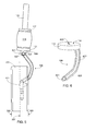
- the upper end of member 109 is rotatably connected to damper-spring mounting platform 113 via a rotational connection generally designated 501.
- a variety of rotational connections 501 are contemplated that would allow mounting platform 113 and the attached damper-spring assembly to pivot about member 109, although in the preferred and illustrated embodiment a bushing within collar 503 is captured by a pin or bolt fastener (not visible) within mount 505 of mounting platform 113, thus allowing the damper-spring assembly attached to platform 113 to rotate about axis 507 of member 109.
- rotational connection 501 is comprised of a ball joint.
- the lower end of spring 115 rests on surface 114 of platform 113, and is captured between mounting platform 113 and a spring retaining member 117.
- spring 115 may consist of either a coil spring or an air spring.
- the damper rod is coupled to mounting platform 113.
- the damper rod is bolted to mounting platform 113 via a threaded hole 603 (see Fig. 6 ).
- damper 119 and spring 115 are coaxially mounted to mounting platform 113.
- nonlinearly-shaped member 109 is comprised of a straight portion 605 and a curved portion 607.
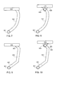
- the shaped member may utilize other shapes.
- Figs. 7 and 8 utilize a continuously curved member 701, where the support member in Fig. 7 is rigidly coupled to mounting platform 113 while the support member in Fig. 8 is rotatably coupled to mounting platform 113.
- the support member illustrated in Figs. 9 and 10 utilize a series of straight sections 901-903, where the support member in Fig. 9 is rigidly coupled to mounting platform 113 while the support member in Fig. 10 is rotatably coupled to mounting platform 113.
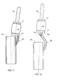
- the system is configured to direct loads along the damper axis towards the center of the tire's contact patch with the road. This aspect is illustrated in Figs. 11 and 12 .
- collar 601 is positioned on the axis of the damper 119, while in the embodiment illustrated in Fig.
- both collars 503 and 601 are positioned on the damper's axis.
- tire 301 can change camber, for example when the car travels over a bump, without imparting lateral force on the end of the assembly, thereby resulting in smoother damping.
- the damper-spring assembly is coupled to wheel support member 101 via damper-spring support member 109.
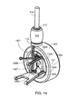
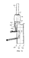
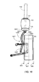
- the nonlinearly-shaped damper-spring support member is coupled to one of the linkage arms, i.e., either to one of the upper linkage arms as illustrated in Fig. 13 or to a lower linkage arm as illustrated in Fig. 14 .
- wheel support member 101 includes multiple mounts for rotatably coupling the wheel support member to the vehicle body via multiple linkage arms 1303-1306, also referred to herein as links.
- the wheel-carrying spindle is not shown although tire 301 is included for clarity.
- a nonlinearly-shaped damper-spring support member is used, thus allowing the damper-spring assembly to overlap tire 301.
- at least 50 percent of the width of mounting platform 113, spring 115 and damper 119 extend past inner tire plane 303 towards tire centerline 307. Locating the damper-spring unit over the tire substantially increases the separation distance between the left vehicle and right vehicle damper-spring units over that achievable utilizing a conventional suspension, thereby providing increased passenger and/or luggage compartment space in this region of the vehicle.
- Fig. 15 provides a front view of the damper-spring assembly shown in Fig.
- Fig. 16 provides a front view of the damper-spring assembly shown in Fig. 13 in which the nonlinearly-shaped damper-spring support member 1301 is rotatably coupled to damper-spring mounting platform 113 via a rotational connection generally designated 1601;
- Fig. 17 provides a front view of the damper-spring assembly shown in Fig. 14 in which the nonlinearly-shaped damper-spring support member 1401 is rigidly coupled to damper-spring mounting platform 113;
- Fig. 18 provides a front view of the damper-spring assembly shown in Fig. 14 in which the nonlinearly-shaped damper-spring support member 1401 is rotatably coupled to damper-spring mounting platform 113 via a rotational connection generally designated 1801.
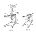
- Figs. 19 and 20 provide a detailed perspective view of the linkage assembly shown in Figs. 13 , 15 and 16 with and without damper-spring support member 1301, respectively.
- the lower end of member 1301 is rotatably connected to upper linkage arm 1305 via a rotational connection generally designated 1307.
- rotational connections 1307 are contemplated that would allow member 1301 to pivot about the upper linkage, in the preferred and illustrated embodiment a bushing within collar 1309 of linkage arm 1305 and collar 1311 of support member 1301 is captured by a pin or bolt fastener (not visible), thus allowing the damper-spring support 1301 to rotate about axis 1313.
- rotational connection 1307 is comprised of a ball joint.
- the upper end of member 1301 is rigidly coupled to a damper-spring mounting platform 113.
- the upper end of member 1301 is rotatably connected to damper-spring mounting platform 113 via a rotational connection generally designated 1601.
- a variety of rotational connections 1601 are contemplated that would allow mounting platform 113 and the attached damper-spring assembly to pivot about member 1301, although in the preferred and illustrated embodiment a bushing within collar 1603 is captured by a pin or bolt fastener (not visible) within mount 1605 of mounting platform 113, thus allowing the damper-spring assembly attached to platform 113 to rotate about axis 1607 of member 1301.
- rotational connection 1601 is comprised of a ball joint.
- nonlinearly-shaped member 1301 is comprised of a straight portion 1315 and a curved portion 1317.
- the shaped member may utilize other shapes.
- Figs. 21 and 22 utilize a continuously curved member 2101, where the support member in Fig. 21 is rigidly coupled to mounting platform 113 while the support member in Fig. 22 is rotatably coupled to mounting platform 113.
- the support member illustrated in Figs. 23 and 24 utilize a series of straight sections 2301-2303, where the support member in Fig. 23 is rigidly coupled to mounting platform 113 while the support member in Fig. 24 is rotatably coupled to mounting platform 113.
- damper-spring support member may be coupled to upper linkage arm 1305 as described above, the damper-spring support member may also be connected elsewhere on the multi-link assembly.
- the damper-spring support member 1401 may also be rotatably coupled to a lower linkage arm.
- nonlinearly-shaped damper-spring support member 1401 passes between the upper linkage arms 1305 and 1306 and is rotatably connected to lower linkage arm 1303 via a rotational connection generally designated 1403.
- Figs. 25 and 26 provide a detailed perspective view of the linkage assembly with and without damper-spring support member 1401, respectively.
- rotational connections 1403 are contemplated that would allow member 1401 to pivot about the lower linkage, in the preferred and illustrated embodiment a bushing within collar 1405 of member 1401 is captured by a pin or bolt fastener (not visible), thus allowing the damper-spring support 1401 to rotate about axis 2501.
- rotational connection 1403 is comprised of a ball joint.
- the upper end of member 1401 is rigidly coupled to a damper-spring mounting platform 113.
- the upper end of member 1401 is rotatably connected to damper-spring mounting platform 113 via a rotational connection generally designated 1801.
- a variety of rotational connections 1801 are contemplated that would allow mounting platform 113 and the attached damper-spring assembly to pivot about member 1401, although in the preferred and illustrated embodiment a bushing within collar 1803 is captured by a pin or bolt fastener (not visible) within mount 1805 of mounting platform 113, thus allowing the damper-spring assembly attached to platform 113 to rotate about axis 1807.
- rotational connection 1801 is comprised of a ball joint.
- nonlinearly-shaped member 1401 is comprised of a straight portion 1407 and a curved portion 1409. It should be appreciated, however, that the shaped member may utilize other shapes.
- Figs. 27 and 28 utilize a continuously curved member 2701, where the support member in Fig. 27 is rigidly coupled to mounting platform 113 while the support member in Fig. 28 is rotatably coupled to mounting platform 113.
- the support member illustrated in Figs. 29 and 30 utilize a series of straight sections 2901-2903, where the support member in Fig. 29 is rigidly coupled to mounting platform 113 while the support member in Fig. 30 is rotatably coupled to mounting platform 113.
- Fig. 31 schematically illustrates the primary components associated with the damper-spring assembly.
- this assembly as well as those illustrated in Figs. 32 and 33 are shown with support member 109 and in a configuration utilizing rotatable coupling 501, this assembly is equally applicable to an assembly in which support member 109 is rigidly coupled to mounting platform 113 (e.g., Fig. 3 embodiment) as well as assemblies in which the damper-spring assembly support member is coupled to a linkage arm (e.g., embodiments illustrated in Figs. 13-18 ).
- Spring 115 which may be a coil spring or an air spring, is positioned between mounting platform 113 and spring retaining member 117.
- damper rod 3101 passes through the center of the spring and is attached to mounting platform 113.
- the entire assembly passes through, and is attached to, a portion 3103 of the vehicle structure.
- Bushings 3105 and 3107 are interposed between vehicle body portion 3103 and damper-spring assembly 100 as shown.
- the damper and the spring are independently mounted to the vehicle structure, thus allowing a gap 3109 to be formed between damper 119 and spring retaining member 117 as shown. By including gap 3109 rather than rigidly coupling the damper to the spring, motion of the damper and spring are decoupled.
- the damper-spring assembly may be mounted to the vehicle body at the top of the assembly.
- a bushing 3201 preferably fabricated from rubber, is interposed between the damper 119 and vehicle body 3203.
- the nonlinearly shaped damper-spring support member may be used with other suspension configurations.
- the order of the damper and spring in the damper-spring assembly may be reversed, although such an arrangement will clearly impact the passenger compartment spacing.
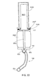
- the axes of the spring and the damper are misaligned and offset from one another.
- Fig. 33 illustrates one such embodiment, this embodiment based on the configuration shown in Fig. 31 .
- damper 3301 is misaligned and offset relative to axis 3303 of spring 3305.
Landscapes
- Engineering & Computer Science (AREA)
- Mechanical Engineering (AREA)
- Vehicle Body Suspensions (AREA)
Applications Claiming Priority (4)
| Application Number | Priority Date | Filing Date | Title |
|---|---|---|---|
| US14/172,147 US8905416B1 (en) | 2014-02-04 | 2014-02-04 | Compact rear suspension damper-spring assembly |
| US14/177,412 US9022401B1 (en) | 2014-02-04 | 2014-02-11 | Compact rear suspension damper-spring assembly |
| US14/512,486 US9073397B1 (en) | 2014-02-04 | 2014-10-13 | Compact rear suspension damper-spring assembly |
| US14/512,511 US9022402B1 (en) | 2014-02-04 | 2014-10-13 | Compact rear suspension damper-spring assembly |
Publications (1)
| Publication Number | Publication Date |
|---|---|
| EP2902220A1 true EP2902220A1 (de) | 2015-08-05 |
Family
ID=51893941
Family Applications (1)
| Application Number | Title | Priority Date | Filing Date |
|---|---|---|---|
| EP14193265.7A Withdrawn EP2902220A1 (de) | 2014-02-04 | 2014-11-14 | Kompakte Dämpfer-Feder-Anordnung für Hinterradaufhängung |
Country Status (3)
| Country | Link |
|---|---|
| EP (1) | EP2902220A1 (de) |
| JP (1) | JP2015147569A (de) |
| CN (2) | CN104816601B (de) |
Cited By (2)
| Publication number | Priority date | Publication date | Assignee | Title |
|---|---|---|---|---|
| EP3922490A1 (de) * | 2020-06-12 | 2021-12-15 | FCA Italy S.p.A. | Doppelquerlenkeraufhängung für ein kraftfahrzeug |
| CN113910901A (zh) * | 2021-11-05 | 2022-01-11 | 青岛理工大学 | 一种基于2-dof并联机构的汽车馈能型智能悬架 |
Families Citing this family (3)
| Publication number | Priority date | Publication date | Assignee | Title |
|---|---|---|---|---|
| JP2015147569A (ja) * | 2014-02-04 | 2015-08-20 | アティエヴァ、インコーポレイテッド | 小型リアサスペンションダンパ・スプリング組立体 |
| CN121219189A (zh) * | 2023-06-08 | 2025-12-26 | 株式会社捷太格特 | 悬架装置 |
| CN119099724A (zh) * | 2024-08-28 | 2024-12-10 | 岚图汽车科技有限公司 | 一种后转向节总成、悬架系统及车辆 |
Citations (15)
| Publication number | Priority date | Publication date | Assignee | Title |
|---|---|---|---|---|
| JPS6022509A (ja) * | 1983-07-13 | 1985-02-05 | Mazda Motor Corp | 自動車のサスペンシヨン |
| FR2609945A1 (fr) * | 1987-01-27 | 1988-07-29 | Peugeot | Dispositif de suspension et de pivotement d'une roue directrice de vehicule automobile |
| EP0548989A1 (de) * | 1991-12-27 | 1993-06-30 | Mazda Motor Corporation | Fahrzeugradaufhängung |
| JPH05169941A (ja) * | 1991-12-17 | 1993-07-09 | Mazda Motor Corp | 車両のサスペンション装置 |
| EP0661183A1 (de) * | 1993-12-29 | 1995-07-05 | FIAT AUTO S.p.A. | Aufhängung für ein gelenktes Rad eines Fahrzeuges unter Benutzung von Mehrfachlenkanordnung |
| US5507510A (en) | 1993-03-26 | 1996-04-16 | Honda Giken Kogyo Kabushiki Kaisha | Multi-link type suspension system |
| FR2753656A1 (fr) * | 1996-09-20 | 1998-03-27 | Peugeot | Dispositif de suspension notamment pour vehicule automobile |
| US6113120A (en) * | 1996-01-19 | 2000-09-05 | Jaguar Cars Limited | Vehicle suspension |
| US6938908B2 (en) | 2002-05-22 | 2005-09-06 | Mazda Motor Corporation | Automotive rear suspension system |
| US6945541B2 (en) | 2003-01-21 | 2005-09-20 | Bose Corporation | Vehicle suspension |
| US20080303234A1 (en) * | 2007-06-05 | 2008-12-11 | Gm Global Technology Operations, Inc. | Joint for Vehicle Steering and Suspension System |
| DE102007047789A1 (de) * | 2007-11-15 | 2009-05-20 | Zf Friedrichshafen Ag | Einzelradaufhängung |
| US7946600B2 (en) | 2008-09-17 | 2011-05-24 | Honda Motor Co., Ltd. | Torsion beam type rear wheel suspension system |
| US8220808B2 (en) | 2009-12-03 | 2012-07-17 | Hyundai Motor Company | Rear suspension of vehicle |
| DE102011000357A1 (de) * | 2011-01-27 | 2012-08-02 | Dr. Ing. H.C. F. Porsche Aktiengesellschaft | Federbein und Stoßdämpfer |
Family Cites Families (6)
| Publication number | Priority date | Publication date | Assignee | Title |
|---|---|---|---|---|
| JPS5267116U (de) * | 1975-11-14 | 1977-05-18 | ||
| JPS58218405A (ja) * | 1982-06-09 | 1983-12-19 | Mazda Motor Corp | 自動車のリヤサスペンシヨン |
| JPH10181324A (ja) * | 1996-12-20 | 1998-07-07 | Fuji Heavy Ind Ltd | 車両のフロントサスペンション |
| JP3650847B2 (ja) * | 2001-09-28 | 2005-05-25 | 日産自動車株式会社 | ショックアブソーバ支持用フォーク部材 |
| DE102004035320A1 (de) * | 2004-07-21 | 2006-02-16 | Bayerische Motoren Werke Ag | Hinterachse eines zweispurigen Kraftfahrzeugs mit Einzelradaufhängung |
| JP2015147569A (ja) * | 2014-02-04 | 2015-08-20 | アティエヴァ、インコーポレイテッド | 小型リアサスペンションダンパ・スプリング組立体 |
-
2014
- 2014-11-04 JP JP2014223888A patent/JP2015147569A/ja active Pending
- 2014-11-14 EP EP14193265.7A patent/EP2902220A1/de not_active Withdrawn
- 2014-12-10 CN CN201410753649.0A patent/CN104816601B/zh not_active Expired - Fee Related
- 2014-12-10 CN CN201420774820.1U patent/CN204801445U/zh not_active Withdrawn - After Issue
Patent Citations (15)
| Publication number | Priority date | Publication date | Assignee | Title |
|---|---|---|---|---|
| JPS6022509A (ja) * | 1983-07-13 | 1985-02-05 | Mazda Motor Corp | 自動車のサスペンシヨン |
| FR2609945A1 (fr) * | 1987-01-27 | 1988-07-29 | Peugeot | Dispositif de suspension et de pivotement d'une roue directrice de vehicule automobile |
| JPH05169941A (ja) * | 1991-12-17 | 1993-07-09 | Mazda Motor Corp | 車両のサスペンション装置 |
| EP0548989A1 (de) * | 1991-12-27 | 1993-06-30 | Mazda Motor Corporation | Fahrzeugradaufhängung |
| US5507510A (en) | 1993-03-26 | 1996-04-16 | Honda Giken Kogyo Kabushiki Kaisha | Multi-link type suspension system |
| EP0661183A1 (de) * | 1993-12-29 | 1995-07-05 | FIAT AUTO S.p.A. | Aufhängung für ein gelenktes Rad eines Fahrzeuges unter Benutzung von Mehrfachlenkanordnung |
| US6113120A (en) * | 1996-01-19 | 2000-09-05 | Jaguar Cars Limited | Vehicle suspension |
| FR2753656A1 (fr) * | 1996-09-20 | 1998-03-27 | Peugeot | Dispositif de suspension notamment pour vehicule automobile |
| US6938908B2 (en) | 2002-05-22 | 2005-09-06 | Mazda Motor Corporation | Automotive rear suspension system |
| US6945541B2 (en) | 2003-01-21 | 2005-09-20 | Bose Corporation | Vehicle suspension |
| US20080303234A1 (en) * | 2007-06-05 | 2008-12-11 | Gm Global Technology Operations, Inc. | Joint for Vehicle Steering and Suspension System |
| DE102007047789A1 (de) * | 2007-11-15 | 2009-05-20 | Zf Friedrichshafen Ag | Einzelradaufhängung |
| US7946600B2 (en) | 2008-09-17 | 2011-05-24 | Honda Motor Co., Ltd. | Torsion beam type rear wheel suspension system |
| US8220808B2 (en) | 2009-12-03 | 2012-07-17 | Hyundai Motor Company | Rear suspension of vehicle |
| DE102011000357A1 (de) * | 2011-01-27 | 2012-08-02 | Dr. Ing. H.C. F. Porsche Aktiengesellschaft | Federbein und Stoßdämpfer |
Cited By (3)
| Publication number | Priority date | Publication date | Assignee | Title |
|---|---|---|---|---|
| EP3922490A1 (de) * | 2020-06-12 | 2021-12-15 | FCA Italy S.p.A. | Doppelquerlenkeraufhängung für ein kraftfahrzeug |
| CN113910901A (zh) * | 2021-11-05 | 2022-01-11 | 青岛理工大学 | 一种基于2-dof并联机构的汽车馈能型智能悬架 |
| CN113910901B (zh) * | 2021-11-05 | 2023-01-24 | 青岛理工大学 | 一种基于2-dof并联机构的汽车馈能型智能悬架 |
Also Published As
| Publication number | Publication date |
|---|---|
| CN204801445U (zh) | 2015-11-25 |
| CN104816601B (zh) | 2017-08-11 |
| CN104816601A (zh) | 2015-08-05 |
| JP2015147569A (ja) | 2015-08-20 |
Similar Documents
| Publication | Publication Date | Title |
|---|---|---|
| US9073400B2 (en) | Motor vehicle multi-link suspension system including a transverse leaf spring | |
| US8152185B2 (en) | Wheel suspension | |
| US9174505B2 (en) | Vehicle independent suspension | |
| CN106457939B (zh) | 车辆悬架 | |
| US8684380B2 (en) | Wheel suspension for automotive vehicle | |
| US9022401B1 (en) | Compact rear suspension damper-spring assembly | |
| US8523209B2 (en) | Semi-trailing arm axle for a motor vehicle | |
| JP5782108B2 (ja) | 車両サスペンションシステム | |
| KR101461902B1 (ko) | 커플드 토션 빔 액슬 타입 현가장치 | |
| US20100270766A1 (en) | Suspension system with single moving element | |
| CN107074051A (zh) | 具有在中央处枢转的横向板簧的车轮悬挂 | |
| CN104816601B (zh) | 紧凑后悬挂减震器弹簧组件 | |
| US9022402B1 (en) | Compact rear suspension damper-spring assembly | |
| US9073397B1 (en) | Compact rear suspension damper-spring assembly | |
| US8905416B1 (en) | Compact rear suspension damper-spring assembly | |
| JP2017001407A (ja) | インホイールモータ駆動装置用サスペンション構造 | |
| US11370258B2 (en) | Trailing blade suspension system with angled blade | |
| EP1910108B1 (de) | Einzelradaufhängung | |
| CN220332409U (zh) | 车辆后独立悬架及车辆 | |
| GB2342902A (en) | Vehicle suspensions | |
| CN111655520B (zh) | 用于汽车的轮悬架装置、保持设备以及汽车 | |
| JPS61202906A (ja) | 自動車のリヤサスペンシヨン | |
| HK1234707B (zh) | 车辆悬架 | |
| HK1234707A1 (en) | Vehicle suspension |
Legal Events
| Date | Code | Title | Description |
|---|---|---|---|
| PUAI | Public reference made under article 153(3) epc to a published international application that has entered the european phase |
Free format text: ORIGINAL CODE: 0009012 |
|
| 17P | Request for examination filed |
Effective date: 20141114 |
|
| AK | Designated contracting states |
Kind code of ref document: A1 Designated state(s): AL AT BE BG CH CY CZ DE DK EE ES FI FR GB GR HR HU IE IS IT LI LT LU LV MC MK MT NL NO PL PT RO RS SE SI SK SM TR |
|
| AX | Request for extension of the european patent |
Extension state: BA ME |
|
| STAA | Information on the status of an ep patent application or granted ep patent |
Free format text: STATUS: THE APPLICATION IS DEEMED TO BE WITHDRAWN |
|
| 18D | Application deemed to be withdrawn |
Effective date: 20160506 |