EP2902253A1 - Kopfstütze und damit bereitgestellter fahrzeugsitz - Google Patents
Kopfstütze und damit bereitgestellter fahrzeugsitz Download PDFInfo
- Publication number
- EP2902253A1 EP2902253A1 EP13840372.0A EP13840372A EP2902253A1 EP 2902253 A1 EP2902253 A1 EP 2902253A1 EP 13840372 A EP13840372 A EP 13840372A EP 2902253 A1 EP2902253 A1 EP 2902253A1
- Authority
- EP
- European Patent Office
- Prior art keywords
- mass body
- headrest
- seat
- mass
- urethane
- Prior art date
- Legal status (The legal status is an assumption and is not a legal conclusion. Google has not performed a legal analysis and makes no representation as to the accuracy of the status listed.)
- Withdrawn
Links
- 230000005484 gravity Effects 0.000 claims abstract description 32
- 239000000463 material Substances 0.000 claims description 40
- 230000002093 peripheral effect Effects 0.000 claims description 19
- JOYRKODLDBILNP-UHFFFAOYSA-N Ethyl urethane Chemical compound CCOC(N)=O JOYRKODLDBILNP-UHFFFAOYSA-N 0.000 description 68
- 239000011347 resin Substances 0.000 description 11
- 229920005989 resin Polymers 0.000 description 11
- 238000000034 method Methods 0.000 description 10
- 238000006073 displacement reaction Methods 0.000 description 7
- 230000001133 acceleration Effects 0.000 description 6
- 230000000694 effects Effects 0.000 description 6
- 239000004744 fabric Substances 0.000 description 6
- 238000005187 foaming Methods 0.000 description 6
- 239000002994 raw material Substances 0.000 description 5
- 238000004519 manufacturing process Methods 0.000 description 4
- 230000001629 suppression Effects 0.000 description 4
- 230000000052 comparative effect Effects 0.000 description 2
- 238000000465 moulding Methods 0.000 description 2
- 230000001603 reducing effect Effects 0.000 description 2
- 239000000853 adhesive Substances 0.000 description 1
- 230000001070 adhesive effect Effects 0.000 description 1
- 238000010097 foam moulding Methods 0.000 description 1
- 239000002184 metal Substances 0.000 description 1
- 238000010008 shearing Methods 0.000 description 1
Images


Classifications
-
- B—PERFORMING OPERATIONS; TRANSPORTING
- B60—VEHICLES IN GENERAL
- B60N—SEATS SPECIALLY ADAPTED FOR VEHICLES; VEHICLE PASSENGER ACCOMMODATION NOT OTHERWISE PROVIDED FOR
- B60N2/00—Seats specially adapted for vehicles; Arrangement or mounting of seats in vehicles
- B60N2/80—Head-rests
- B60N2/888—Head-rests with arrangements for protecting against abnormal g-forces, e.g. by displacement of the head-rest
-
- F—MECHANICAL ENGINEERING; LIGHTING; HEATING; WEAPONS; BLASTING
- F16—ENGINEERING ELEMENTS AND UNITS; GENERAL MEASURES FOR PRODUCING AND MAINTAINING EFFECTIVE FUNCTIONING OF MACHINES OR INSTALLATIONS; THERMAL INSULATION IN GENERAL
- F16F—SPRINGS; SHOCK-ABSORBERS; MEANS FOR DAMPING VIBRATION
- F16F7/00—Vibration-dampers; Shock-absorbers
- F16F7/10—Vibration-dampers; Shock-absorbers using inertia effect
- F16F7/104—Vibration-dampers; Shock-absorbers using inertia effect the inertia member being resiliently mounted
- F16F7/108—Vibration-dampers; Shock-absorbers using inertia effect the inertia member being resiliently mounted on plastics springs
-
- B—PERFORMING OPERATIONS; TRANSPORTING
- B60—VEHICLES IN GENERAL
- B60N—SEATS SPECIALLY ADAPTED FOR VEHICLES; VEHICLE PASSENGER ACCOMMODATION NOT OTHERWISE PROVIDED FOR
- B60N2/00—Seats specially adapted for vehicles; Arrangement or mounting of seats in vehicles
- B60N2/24—Seats specially adapted for vehicles; Arrangement or mounting of seats in vehicles for particular purposes or particular vehicles
- B60N2/42—Seats specially adapted for vehicles; Arrangement or mounting of seats in vehicles for particular purposes or particular vehicles the seat constructed to protect the occupant from the effect of abnormal g-forces, e.g. crash or safety seats
- B60N2/4207—Seats specially adapted for vehicles; Arrangement or mounting of seats in vehicles for particular purposes or particular vehicles the seat constructed to protect the occupant from the effect of abnormal g-forces, e.g. crash or safety seats characterised by the direction of the g-forces
- B60N2/4214—Seats specially adapted for vehicles; Arrangement or mounting of seats in vehicles for particular purposes or particular vehicles the seat constructed to protect the occupant from the effect of abnormal g-forces, e.g. crash or safety seats characterised by the direction of the g-forces longitudinal
- B60N2/4228—Seats specially adapted for vehicles; Arrangement or mounting of seats in vehicles for particular purposes or particular vehicles the seat constructed to protect the occupant from the effect of abnormal g-forces, e.g. crash or safety seats characterised by the direction of the g-forces longitudinal due to impact coming from the rear
-
- B—PERFORMING OPERATIONS; TRANSPORTING
- B60—VEHICLES IN GENERAL
- B60N—SEATS SPECIALLY ADAPTED FOR VEHICLES; VEHICLE PASSENGER ACCOMMODATION NOT OTHERWISE PROVIDED FOR
- B60N2/00—Seats specially adapted for vehicles; Arrangement or mounting of seats in vehicles
- B60N2/80—Head-rests
-
- B—PERFORMING OPERATIONS; TRANSPORTING
- B60—VEHICLES IN GENERAL
- B60N—SEATS SPECIALLY ADAPTED FOR VEHICLES; VEHICLE PASSENGER ACCOMMODATION NOT OTHERWISE PROVIDED FOR
- B60N2/00—Seats specially adapted for vehicles; Arrangement or mounting of seats in vehicles
- B60N2/80—Head-rests
- B60N2002/899—Head-rests characterised by structural or mechanical details not otherwise provided for
Definitions
- the present invention relates to a headrest and to a vehicle seat provided therewith.
- Patent Document 1 A vehicle seat in which a dynamic damper is structured by integrally supporting a mass body within a pad is disclosed in following Patent Document 1. Further, a headrest in which a dynamic damper is structured by providing an elastic resin material that is injected into a molding bag and foam-molded and a weight that is fixedly placed with respect to the molding bag, is disclosed in following Patent Document 2.
- Patent Document 2 a headrest in which a dynamic damper is structured by providing an elastic resin material that is injected into a molding bag and foam-molded and a weight that is fixedly placed with respect to the molding bag.
- an object of the present invention is to provide a headrest and a vehicle seat provided therewith, that can reduce load to the neck portion of a vehicle occupant at the time of a rear collision while ensuring the NV performance.
- a headrest relating to a first aspect of the present invention comprises: a headrest pad that is disposed at an inner side of a headrest skin and that is elastically deformable; a first mass body that is supported by the headrest pad; and a second mass body that is supported by the headrest pad, and that is disposed apart from the first mass body.
- the first mass body and the second mass body are supported by the headrest pad that is elastically deformable.
- a dynamic damper that has the headrest pad, the first mass body and the second mass body, is structured. Therefore, seat vibrations are suppressed by setting the frequency characteristic of the dynamic damper such that the dynamic damper works in the frequency band of seat vibrations for which suppression is desired.
- the mass per each mass body can be made to be small. Due thereto, at the time of a rear collision, the amplitudes of the first mass body and the second mass body in the seat longitudinal direction are respectively suppressed due to the lowering of the respective inertial forces of the first mass body and the second mass body. Accordingly, load to the neck portion of the vehicle occupant, that is caused by vibration of the first mass body and the second mass body in the seat longitudinal direction, is reduced.
- the first mass body and the second mass body are disposed lined-up apart at left and right sides in a seat transverse direction with respect to a seat transverse direction central line at the headrest.
- the first mass body and the second mass body are disposed lined-up apart at left and right sides in the seat transverse direction with respect to the seat transverse direction central line at the headrest. Therefore, at the time of a rear collision, when the head portion of the vehicle occupant is pushed-against the headrest and is displaced toward between the first mass body and the second mass body, the first mass body and the second mass body can be displaced in directions of moving away from one another.
- a product of mass of the first mass body and a distance from a center of gravity of the headrest to a center of gravity of the first mass body, and a product of mass of the second mass body and a distance from the center of gravity of the headrest to a center of gravity of the second mass body are set to be equivalent.
- respective resonance frequencies of the first mass body and the second mass body, that are respectively supported by headrest pad differ.
- the frequency band of seat vibrations that can be suppressed can be broadened.
- the headrest pad has a first cushion material that supports the first mass body and the second mass body and is elastically deformable, and a second cushion material whose elastic coefficient is higher than that of the first cushion material.
- the first cushion material of the headrest pad is elastically deformable, and the first mass body and the second mass body are supported by this first cushion material.
- a dynamic damper that has the first cushion material, the first mass body and the second mass body, is structured, and seat vibrations can be suppressed by this dynamic damper.
- the elastic coefficient of the second cushion material of the headrest pad is set to be higher than that of the first cushion material. Therefore, at the time of a rear collision, owing to the second cushion material, the supporting rigidity of the headrest with respect to the head portion of the vehicle occupant is increased, and the respective amplitudes of the first mass body and the second mass body also are suppressed. Further, due to the latter, load to the neck portion of the vehicle occupant, that is caused by respective vibrations of the first mass body and the second mass body in the seat longitudinal direction, is reduced.
- the first cushion material has a first overlap portion that is set at a position that overlaps the first mass body as seen in a seat front view, and a second overlap portion that is set at a position that overlaps the second mass body as seen in a seat front view
- the second cushion material has a third overlap portion that is set at a position that overlaps the first mass body and the first overlap portion as seen in a seat front view, and a fourth overlap portion that is set at a position that overlaps the second mass body and the second overlap portion as seen in a seat front view.
- the first mass body in a case in which the headrest vibrates in the seat longitudinal direction at the time when the seat vibrates usually, the first mass body is displaced while elastically deforming the first overlap portion, and the second mass body is displaced while elastically deforming the second overlap portion. For these reasons, vibrations are damped.
- the third overlap portion suppresses vibration of the first mass body.
- the fourth overlap portion suppresses vibration of the second mass body. For these reasons, at the time of a rear collision, the respective amplitudes of the first mass body and the second mass body in the seat longitudinal direction are suppressed effectively, and therefore, load to the neck portion of the vehicle occupant, that is caused by respective vibrations of the first mass body and the second mass body in the seat longitudinal direction, is effectively reduced.
- the first cushion material covers an entire periphery of a peripheral edge of the first mass body, and covers an entire periphery of a peripheral edge of the second mass body.
- the first cushion material covers the entire peripheries of the respective peripheral edges of the first mass body and the second mass body. Therefore, setting of the frequency characteristic of the dynamic damper is easy as compared with, for example, a structure in which the first mass body and the second mass body are covered by the first cushion material and the second cushion material. Namely, seat vibrations are suppressed by setting the frequency characteristic of the dynamic damper by adjusting the respective masses of the first mass body and the second mass body or the rigidity, volume, shape or the like of the first cushion material, such that the dynamic damper works in the frequency band of the seat vibrations for which suppression is desired.
- a vehicle seat relating to an eighth aspect of the present invention comprises: a seat cushion on which a vehicle occupant sits; a seat back that is supported at a rear end portion of the seat cushion; and the headrest relating to any one aspect of the first aspect through the seventh aspect that is disposed at an upper end portion of the seat back and supports a head portion of the vehicle occupant.
- FIG. 1 A first embodiment of the present invention is described by using Fig. 1 through Fig. 5 .
- arrow FR that is shown appropriately in these drawings indicates the vehicle front side
- arrow UP indicates the vehicle upper side
- arrow W indicates the vehicle transverse direction.
- the vehicle longitudinal direction and the seat longitudinal direction are the same direction
- the vehicle vertical direction and the seat vertical direction are the same direction
- the vehicle transverse direction and the seat transverse direction are the same direction.
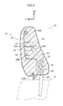
- a headrest of a vehicle seat relating to the present embodiment is shown in Fig. 1 in a cross-sectional view seen from the front of the seat, and a cross-sectional view along line 2-2 of Fig. 1 is shown in Fig. 2 .
- a vehicle seat 10 shown in these drawings has an unillustrated seat cushion that is mounted in an automobile and on which a vehicle occupant sits.
- a seat back 12 is reclinably supported at the rear end portion of the seat cushion. Note that, in Fig. 1 and Fig. 2 , only the upper end portion of the seat back 12 is shown by the two-dot chain line.
- a headrest 14 that supports the head portion of the vehicle occupant is disposed at the upper end portion of the seat back 12.
- the headrest 14 is structured to include a headrest main body 16 that is shaped as a pillow and supports the head portion of the vehicle occupant, and a headrest stay 18 that extends toward the vehicle lower side from the bottom surface of this headrest main body 16.
- the headrest stay 18 is a structure in which a pipe made of metal is formed into an upside-down U-shape, and has a pair of left and right leg portions 18A.
- the pair of left and right leg portions 18A are supported at the seat back 12 by being inserted into an unillustrated headrest support of the seat back 12. Due thereto, the headrest 14 is supported at the seat back 12.
- the leg portions 18A extend in the seat height direction, and the upper portion sides thereof are disposed within the headrest main body 16. Further, the regions, that are disposed at the interior of the headrest main body 16, of the leg portions 18A have curved portions at the lower end portions thereof, and the regions, that are further toward the seat upper side than these curved portions, are inclined slightly forward toward the seat front side. Further, the upper ends of the leg portions 18A are connected in the seat transverse direction by a connecting portion 18B.
- the headrest main body 16 has a headrest pad 20 that structures the cushion portion of the headrest main body 16 and is elastically deformable, a headrest skin (cover) 22 that covers the headrest pad 20, and a resin cover 24 that is embedded within the headrest pad 20.
- Stay insert-through holes 22A that are for the leg portions 18A of the headrest stay 18 to be inserted therethrough, are formed in the lower end portion of the headrest skin 22. As shown in Fig. 2 , the seat front side of the stay insert-through holes 22A is a sewn-together portion 22B.
- the resin cover 24 (also called “resin pad”, “insert”) is disposed at the upper portion side and the seat front side of the headrest stay 18.
- This resin cover 24 has a front wall 24A whose obverse faces toward the seat front side.
- a bottom wall 24B that extends toward the seat rear side is formed from the lower end portion of the front wall 24A.
- side walls 24C (see Fig. 1 ) that extend toward the seat rear side are formed from the end portions at the seat transverse direction both sides of the front wall 24A.
- an anchor portion that is anchored on the headrest stay 18 is formed at the resin cover 24.
- plural ribs 24D that extend in the seat transverse direction, and plural ribs (not illustrated) that extend in the seat vertical direction, are formed at the surface, that faces toward the seat rear side, of the front wall 24A.
- the headrest pad 20 that is shown in Fig. 1 and Fig. 2 has a first urethane 30 (a "spring element" in the broad sense) that serves as a first cushion material and is elastically deformable, and a second urethane 32 that serves as a second cushion material and whose elastic coefficient is higher (the second urethane 32 is harder) than that of the first urethane 30.
- Both the first urethane 30 and the second urethane 32 are disposed at the inner side of the headrest skin 22, and are formed by foam-molding urethane. Further, in the present embodiment, the first urethane 30 (inner side foamed urethane) is embedded in the second urethane 32 (outer side foamed urethane).
- the first urethane 30 is disposed at the seat lower side of the resin cover 24, and the seat transverse direction is the length direction thereof, and both end portions in the seat transverse direction of the first urethane 30 are fixed, by the adhesive force of the urethane itself, to the leg portions 18A of the headrest stay 18. Namely, the first urethane 30 spans between the pair of left and right leg portions 18A of the headrest stay 18.
- a first mass body 40 and a second mass body 42 are embedded in the length direction intermediate portion of the first urethane 30, and the first mass body 40 and the second mass body 42 are disposed so as to be lined-up apart at the left and right sides in the seat transverse direction with respect to a seat transverse direction central line CL. Namely, the respective peripheral edges of the first mass body 40 and the second mass body 42 are covered, over the entire peripheries thereof, by the first urethane 30, and the first mass body 40 and the second mass body 42 are respectively supported by the first urethane 30. Further, in the present embodiment, the peripheral edge of the first mass body 40 and the peripheral edge of the second mass body 42 are, over the respective entire peripheries (entire regions) thereof, joined to the first urethane 30.
- the first urethane 30 has first overlap portions 30A, 30B (see Fig. 3 ) that are set at positions overlapping the first mass body 40 as seen in a seat front view.
- a cross-sectional view along line 3-3 of Fig. 1 is shown in Fig. 3 .
- the first overlap portion that is set at the seat front side with respect to the first mass body 40 is indicated by reference numeral 30A
- the first overlap portion that is set at the seat rear side with respect to the first mass body 40 is indicated by reference numeral 30B.
- the first urethane 30 has second overlap portions 30C, 30D that are set at positions overlapping the second mass body 42 as seen in a seat front view.
- the second overlap portion that is set at the seat front side with respect to the second mass body 42 is indicated by reference numeral 30C
- the second overlap portion that is set at the seat rear side with respect to the second mass body 42 is indicated by reference numeral 30D.
- the volume of the second urethane 32 is set to be greater than the volume of the first urethane 30.
- the second urethane 32 has third overlap portions 32A, 32B that are set at positions overlapping the first mass body 40 and the first overlap portions 30A, 30B as seen in a seat front view.
- the third overlap portion that is set at the seat front side with respect to the first mass body 40 and the first overlap portions 30A, 30B is indicated by reference numeral 32A
- the third overlap portion that is set at the seat rear side is indicated by reference numeral 32B, respectively.
- the second urethane 32 has fourth overlap portions 32C, 32D that are set as positions overlapping the second mass body 42 and the second overlap portions 30C, 30D as seen in a seat front view.
- the fourth overlap portion that is set at the seat front side with respect to the second mass body 42 and the second overlap portions 30C, 30D is indicated by reference numeral 32C
- the fourth overlap portion that is set at the seat rear side is indicated by reference numeral 32D, respectively.
- the setting of the respective elastic coefficients at the first urethane 30 and the second urethane 32 that are shown in Fig. 1 and Fig. 2 is described by using an example.
- a material having a higher elastic coefficient than the material of the first urethane 30 is used for the second urethane 32.
- the same material as the first urethane 30 may be used for the second urethane 32, and the foaming ratio of the second urethane 32 may be set to be lower than the foaming ratio of the first urethane 30.
- the spring constant of the first urethane 30 is set to a spring constant that is optimal for addressing the NV in a case of assuming vibration at usual times, i.e., as an example, in a case in which the amplitude of the second mass body 42, that is the heavier among the first mass body 40 and the second mass body 42, is less than a predetermined value (a region of small displacement).
- the spring constant of the second urethane 32 is set to a spring constant that is optimal for addressing a rear collision in a case of assuming a collision, i.e., as an example, in a case in which the amplitude of the second mass body 42 is greater than or equal to the predetermined value (a region of large displacement).
- the spring characteristic of the second urethane 32 may be set in consideration of a range of spring constants that are comfortable in cases of supporting the head portion of the vehicle occupant.
- the first mass body 40 and the second mass body 42 are disposed between the pair of left and right leg portions 18A of the headrest stay 18, and are set at positions that overlap that pair of left and right leg portions 18A as seen in the seat side view shown in Fig. 2 .
- the second mass body 42 is illustrated by the dashed line, but the position of placement of the first mass body 40 (see Fig. 1 ) as seen in a seat side view is set to a position that coincides with the position of placement of the second mass body 42 as seen in a seat side view.
- the center of gravity (the center) of the first mass body 40 (see Fig. 1 ) and the center of gravity (the center) of the second mass body 42 overlap the pair of left and right leg portions 18A as seen in a seat side view.
- the projected surface areas, as seen in a seat front view, of the portions of the first mass body 40 and the second mass body 42 that are shown in Fig. 1 , which portions contact the first urethane 30, are set to be larger than the projected surface areas, as seen in a seat side view, of the aforementioned contacting portions. Therefore, at the first urethane 30, the rigidity, with respect to displacement in the seat longitudinal direction, of the first mass body 40 is set to be higher than the rigidity, with respect to displacement in the seat transverse direction, of the first mass body 40, and the rigidity, with respect to displacement in the seat longitudinal direction, of the second mass body 42 is set to be higher than the rigidity, with respect to displacement in the seat transverse direction, of the second mass body 42. In other words, at the first mass body 40 and the second mass body 42 that are supported by the first urethane 30, the resonance frequencies in the seat longitudinal direction are set to be higher than the resonance frequencies in the seat transverse direction.
- the respective resonance frequencies of the first mass body 40 and the second mass body 42, that are respectively supported by the first urethane 30, differ.
- the resonance frequency of the second mass body 42 is set to be lower than the resonance frequency of the first mass body 40.
- the first mass body 40 that is light is set at a position whose distance from the seat transverse direction central line CL is longer than that of the second mass body 42 that is heavy, so that the center of gravity position of the headrest 14 does not tend toward the left or the right.
- the product of the mass of the first mass body 40 and the distance from the center of gravity (not shown) of the headrest 14 to a center of gravity G1 of the first mass body 40, and the product of the mass of the second mass body 42 and the distance from the center of gravity of the headrest 14 to a center of gravity G2 of the second mass body 42 are set to be equivalent (the same in the present embodiment).
- the center of gravity of the headrest 14 is not illustrated, it is set at a seat transverse direction central position.
- the structure of the present embodiment can be said to be a structure having a main vibration system, in which a seat skeleton portion of the vehicle seat 10 that is disposed at the vehicle floor is the spring and in which the entire headrest 14 is the mass, and having plural dynamic dampers having a spring and a mass at the headrest 14.
- a method of manufacturing the headrest 14 is described next.
- the resin cover 24 is mounted to the headrest stay 18 shown in Fig. 1 and Fig. 2 .
- the first mass body 40 and the second mass body 42 are set between the leg portions 18A of the headrest stay 18, with respect to a stay assembly 26 that has the resin cover 24 and the headrest stay 18 that are shown in Fig. 1 .
- the first mass body 40 and the second mass body 42 are fixed to the leg portions 18A.
- the headrest skin 22 that is in a state before being sewn at the sewn-together portion 22B shown in Fig. 2 , is hung upside-down, and the stay assembly 26 is, in an upside-down posture, inserted into this headrest skin 22 from the upper side. Then, the leg portions 18A of the headrest stay 18 are inserted through the stay insert-through holes 22A. In this state, due to the raw material of the second urethane 32 being injected and foam-molded in the interior of the headrest skin 22 (second-stage foaming step), the headrest pad 20 is formed. Finally, the headrest skin 22 is sewn at the sewn-together portion 22B.
- the first mass body 40 and the second mass body 42 are fixed to the leg portions 18A in the first-stage foaming step. Therefore, in the second-stage foaming step, a situation in which the first mass body 40 and the second mass body 42 fall-out from their planned placement positions, or the like, can be avoided. Further, the present embodiment is not a form in which the first mass body 40 and the second mass body 42 are mounted by using a mounting bracket and a fastening tool, and therefore, the number of assembly steps and the number of parts are reduced.
- the first mass body 40 and the second mass body 42 are supported by the headrest pad 20 that is elastically deformable, at the inner side of the headrest skin 22 of the vehicle seat 10 that is shown in Fig. 1 .
- a dynamic damper 28 that has the headrest pad 20, the first mass body 40 and the second mass body 42, is structured. Therefore, seat vibrations are suppressed by setting the frequency characteristic of the dynamic damper 28 such that the dynamic damper 28 works in the frequency band of seat vibrations for which suppression is desired.
- the mass per each of the mass bodies can be made to be small. Due thereto, at the time of a rear collision, the amplitudes of the first mass body 40 and the second mass body 42 in the seat longitudinal direction are respectively suppressed due to the lowering of the respective inertial forces of the first mass body 40 and the second mass body 42. Accordingly, load to the neck portion of the vehicle occupant, that is caused by vibrations of the first mass body 40 and the second mass body 42 in the seat longitudinal direction, is reduced.
- the load to the neck portion of the vehicle occupant at the time of a rear collision is described further here.
- the greater the amplitudes of the first mass body 40 and the second mass body 42 toward the seat rear side the smaller the pushing force of the headrest 14 with respect to the head portion of the vehicle occupant.
- the difference between the acceleration that is applied to the head portion of the vehicle occupant and the acceleration that is applied to the chest portion becomes large, and the load to the neck portion of the vehicle occupant becomes large.
- the amplitudes of the first mass body 40 and the second mass body 42 in the seat longitudinal direction are respectively suppressed due to the lowering of the respective inertial forces of the first mass body 40 and the second mass body 42. Therefore, the difference between the acceleration that is applied to the head portion of the vehicle occupant and the acceleration that is applied to the chest portion also is suppressed, and therefore, the load to the neck portion of the vehicle occupant is reduced.
- the first mass body 40 and the second mass body 42 are disposed so as to be lined-up apart at the left and right sides in the seat transverse direction with respect to the seat transverse direction central line CL at the headrest 14. Therefore, when, at the time of a rear collision, the head portion of the vehicle occupant is pushed-against the headrest 14 and is displaced toward between the first mass body 40 and the second mass body 42, the first mass body 40 and the second mass body 42 can be displaced in directions of moving apart from one another (toward the vehicle transverse direction outer sides).
- the product of the mass of the first mass body 40 and the distance from the center of gravity (not shown) of the headrest 14 to the center of gravity G1 of the first mass body 40, and the product of the mass of the second mass body 42 and the distance from the center of gravity of the headrest 14 to the center of gravity G2 of the second mass body 42 are set to be equivalent. Therefore, the moment, that relates to the center of gravity G1 of the first mass body 40 and is centered around the center of gravity of the headrest 14, and the moment, that relates to the center of gravity G2 of the second mass body 42 and is centered around the center of gravity of the headrest 14, are in equilibrium at the left and the right. Namely, the left/right balance of the headrest 14 is maintained good.
- the mass of the first mass body 40 and the mass of the second mass body 42 being different, the respective resonance frequencies of the first mass body 40 and the second mass body 42, that are respectively supported by the first urethane 30, differ. Therefore, the frequency band of seat vibrations that can be suppressed can be broadened.
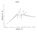
- FIG. 4 A graph comparing the NV performance in a case of applying the structure relating to the present embodiment and in a case of applying a comparative structure is shown in Fig. 4 .
- the magnitude of the vibration level is plotted on the vertical axis
- frequency is plotted on the horizontal axis.
- Solid line D shows the characteristic in a case in which the structure relating to the present embodiment is applied
- point a and point b are the respective resonance frequencies of the first mass body and the second mass body that have been set to be different from one another.
- two-dot chain line E shows the characteristic in a case in which a structure, in which one mass body is disposed instead of the first mass body and the second mass body, is applied.
- the mass of the mass body in the structure whose characteristic is shown by the two-dot chain line E is equal to the sum of the respective masses of the first mass body and the second mass body of the structure whose characteristic is shown by the solid line D.
- dashed line F shows the characteristic in a case in which a structure, in which a dynamic damper is not provided at the headrest, is applied.
- the structure relating to present embodiment has an improved NV performance even when compared with both the structure in which a dynamic damper is not provided at the headrest and a structure in which a dynamic damper having one mass body is provided at the headrest.
- the NV performance of the structure relating to the present embodiment in a case in which it is fine for the NV performance of the structure relating to the present embodiment to be a similar level as the NV performance of the structure whose characteristic is shown by the two-dot chain line E, it suffices of the sum of the respective masses of the first mass body and the second mass body to be less than the mass of the mass body in the structure whose characteristic is shown by the two-dot chain line E. Accordingly, lightening of the weights of the mass bodies and a reduction in the materials costs are possible.
- the headrest pad 20 shown in Fig. 3 has the first urethane 30, that is elastically deformable and that supports the first mass body 40 and the second mass body 42, and has the second urethane 32 whose elastic coefficient is higher than that of the first urethane 30. Therefore, at the time of a rear collision, owing to the second urethane 32, the supporting rigidity of the headrest 14 with respect to the head portion of the vehicle occupant is increased, and the respective amplitudes of the first mass body 40 and the second mass body 42 also are suppressed. Further, due to the latter, load to the neck portion of the vehicle occupant, that is caused by respective vibrations of the first mass body 40 and the second mass body 42 in the seat longitudinal direction, is reduced.
- the first mass body 40 in cases in which the headrest 14 vibrates in the seat longitudinal direction at times when the seat vibrates usually, the first mass body 40 is displaced while elastically deforming the first overlap portions 30A, 30B, and the second mass body 42 is displaced while elastically deforming the second overlap portions 30C, 30D. For these reasons, the vibrations are damped.
- the third overlap portions 32A, 32B suppress the vibration of the first mass body 40.
- the fourth overlap portions 32C, 32D suppress the vibration of the second mass body 42.
- the respective amplitudes of the first mass body 40 and the second mass body 42 in the seat longitudinal direction are effectively suppressed, and therefore, the load on the neck portion of the vehicle occupant, that is caused by respective vibrations of the first mass body 40 and the second mass body 42 in the seat longitudinal direction, is reduced effectively.
- the first urethane 30 covers the entire peripheries of the respective peripheral edges the first mass body 40 and the second mass body 42. Therefore, setting of the frequency characteristic of the dynamic damper 28 is easy as compared with a structure in which, for example, the first mass body 40 and the second mass body 42 are covered by the first urethane 30 and the second urethane 32. Namely, seat vibrations are suppressed by setting the frequency characteristic of the dynamic damper 28 by adjusting the respective masses the first mass body 40 and the second mass body 42, or the rigidity, the volume, the shape or the like of the first urethane 30, such that the dynamic damper 28 works in the frequency band of seat vibrations for which suppression is desired.
- load to the neck portion of a vehicle occupant at the time of a rear collision can be reduced while the NV performance is ensured.
- the respective resonance frequencies of the first mass body and the second mass body may be set to different values by making the respective masses of the first mass body and the second mass body, that are supported by the first urethane 30 (the first cushion material), be the same and changing the elastic coefficients of the regions that support the first mass body and the second mass body.
- the elastic coefficients of the regions that support the first mass body and the second mass body for example, it suffices to change the surface area of contact between the first urethane 30 and the first mass body and the surface area of contact between the first urethane 30 and the second mass body.
- first mass body and the second mass body are referred to collectively as the mass bodies.
- a method of joining portions of the mass bodies to the first urethane 30 for example, there is a method in which, in a state in which cloth bodies cover portions of the mass bodies, the raw material of the first urethane 30 is supplied to the peripheries of the mass bodies and integrally foamed, and thereafter, the cloth bodies are pulled-off and are removed from the outer peripheries of the mass bodies.
- the mass bodies and the first urethane 30 are not joined, and gaps are formed between the both. Note that the aforementioned cloth bodies do not have to be pulled-off, and, instead of the aforementioned cloth bodies, felt, papers, seals, or the like may be applied.
- the raw material of the first urethane 30 may be supplied to the peripheries of the mass bodies and foamed integrally, and thereafter, the tweezers may be pulled-away and removed from the outer peripheries of the mass bodies.
- portions of the mass bodies and the first urethane 30 may be coated on the portions of the mass bodies that are not to be joined, and thereafter, the raw material of the first urethane 30 may be supplied to the peripheries of the mass bodies and foamed integrally.
- the manufacturing steps can be simplified and the materials costs also can be reduced, as compared with a method using cloth bodies or the like.
- portions of the mass bodies and the first urethane 30 are in states of contacting without being joined. At the regions that are in states of contact without being joined, spring force in the shearing direction does not work, but spring force in a compressing direction works even with respect to minute vibrations.
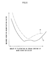
- FIG. 5 A graph that compares the robustness in a case of applying the structure relating to the above-described modified example of the first embodiment and in a case of applying the comparative structure, is shown in Fig. 5 .
- the maximum vibration magnification factor is plotted on the vertical axis
- the amount of fluctuation in the spring constant of the main vibration system is plotted on the horizontal axis.
- Solid line G shows the characteristic in the case in which the above-described modified example is applied.
- two-dot chain line H shows the characteristic in the case in which a structure, in which one mass body is disposed instead of the first mass body and the second mass body (the structure whose characteristic is shown by the two-dot chain line E of Fig.
- the region in which the maximum vibration magnification factor is low is broad, and the robustness of the amplitude level reducing effect is high, as compared with the structure having the dynamic damper that is provided with one mass body.
- the headrest pad 20, that is applied to the first embodiment shown in Fig. 1 and the like, is structured by the first urethane 30 and the second urethane 32 whose elastic coefficients differ from one another.
- the headrest pad that is applied to the second embodiment is structured by one type of foamed urethane.
- the other structures are structures similar to the first embodiment.
- the headrest pad of the second embodiment is disposed at the inner side of the headrest skin and is elastically deformable, in the same way as the first embodiment. Further, the first mass body (40) and the second mass body (42) are supported at this headrest pad, and the second mass body (42) is disposed apart from the first mass body (40).
- seat vibrations are suppressed by setting the frequency characteristic of the dynamic damper (28). Further, at the time of a rear collision, the amplitudes of the first mass body (40) and the second mass body (42) in the seat longitudinal direction are respectively suppressed due to the lowering of the respective inertial forces of the first mass body (40) and the second mass body (42). Accordingly, in the second embodiment as well, load to the neck portion of the vehicle occupant at the time of a rear collision can be reduced while the NV performance is ensured.
- the headrest 14 is provided with the two mass bodies that are the first mass body 40 and the second mass body 42.
- the headrest may be provided with three or more mass bodies including the first mass body and the second mass body, and may be structured such that these mass bodies are disposed apart from one another.
- the headrest in addition to the first mass body and the second mass body, the headrest may be provided with, for example, a third mass body that is supported by the headrest pad and is disposed apart from the first mass body and the second mass body.
- one or both of the first mass body and the second mass body may be disposed so as to not be embedded in the headrest pad so as to, for example, be provided at the upper end portion of the headrest pad and be disposed so as to be partially exposed from the headrest pad, or the like.
- At least one of the first cushion material and the second cushion material may be made to be another cushion material such as, for example, a resin foamed body other than urethane, or felt, rubber, or the like.
- the first mass body and the second mass body may be disposed so as to be apart in the seat vertical direction.
- the respective inertial forces of the first mass body and the second mass body can be made to be small, and therefore, the displacement of the first mass body and the second mass body at the time of a rear collision is suppressed.
- the product of the mass of the first mass body and the distance from the center of gravity of the headrest to the center of gravity of the first mass body, and the product of the mass of the second mass body and the distance from the center of gravity of the headrest to the center of gravity of the second mass body can also be set so as to not be equivalent.
- the respective masses of the first mass body and the second mass body may be set to be the same.
- the respective resonance frequencies of the first mass body and the second mass body may be set to different values by setting the respective masses of the first mass body and the second mass body to be the same and changing the elastic coefficients of the regions that respectively support the first mass body and the second mass body.
- the respective resonance frequencies of the first mass body and the second mass body, that are respectively supported by the headrest may be set to be the same.
- first cushion material does not have at least one of the first overlap portion and the second overlap portion
- second cushion material does not have at least one of the third overlap portion and the fourth overlap portion
- first overlap portion and the third overlap portion may respectively be set at only either one side of the seat front side and the seat rear side of the first mass body.
- second overlap portion and the fourth overlap portion may respectively be set at only either one side of the seat front side and the seat rear side of the second mass body.
- a portion of the peripheral edge of the first mass body may be covered by the first cushion material, and another portion of the peripheral edge of this first mass body may be covered by the second cushion material. Further, a portion of the peripheral edge of the second mass body may be covered by the first cushion material, and another portion of the peripheral edge of this second mass body may be covered by the second cushion material.
- the concept of "equivalent” that is recited in the third aspect of the present invention includes cases of "the same” as in the above-described embodiment, and in addition, also includes cases that are substantially the same and cannot be strictly said to be the same, but that can obtain operation/effects that are similar to those of cases of "the same” and can be interpreted as being substantially “equivalent”.
- the concept of "covers an entire periphery of a peripheral edge of the mass body (the first mass body, the second mass body)" in the seventh aspect of the present invention includes cases in which the peripheral edges of the mass bodies (the first mass body 40, the second mass body 42) are covered over the entire peripheries thereof as in the above-described embodiment, and in addition, also includes cases in which, although the peripheral edges of the mass bodies (the first mass body, the second mass body) are covered over substantially the entire peripheries thereof, portions that are not covered locally exist, and it cannot be strictly said that the peripheral edges of the mass bodies (the first mass body, the second mass body) are covered over the entire peripheries thereof, but that can obtain operation/effects that are similar to those of cases in which the peripheral edges of the mass bodies (the first mass body, the second mass body) are covered over the entire peripheries thereof and can be interpreted as substantially the entire peripheries of the peripheral edges of the mass bodies (the first mass body, the second mass body) being covered.
Landscapes
- Engineering & Computer Science (AREA)
- Mechanical Engineering (AREA)
- Aviation & Aerospace Engineering (AREA)
- Transportation (AREA)
- General Engineering & Computer Science (AREA)
- Seats For Vehicles (AREA)
- Chair Legs, Seat Parts, And Backrests (AREA)
Applications Claiming Priority (2)
| Application Number | Priority Date | Filing Date | Title |
|---|---|---|---|
| JP2012211327A JP5696706B2 (ja) | 2012-09-25 | 2012-09-25 | ヘッドレスト及びこれを備えた車両用シート |
| PCT/JP2013/072609 WO2014050391A1 (ja) | 2012-09-25 | 2013-08-23 | ヘッドレスト及びこれを備えた車両用シート |
Publications (2)
| Publication Number | Publication Date |
|---|---|
| EP2902253A1 true EP2902253A1 (de) | 2015-08-05 |
| EP2902253A4 EP2902253A4 (de) | 2016-04-20 |
Family
ID=50387800
Family Applications (1)
| Application Number | Title | Priority Date | Filing Date |
|---|---|---|---|
| EP13840372.0A Withdrawn EP2902253A4 (de) | 2012-09-25 | 2013-08-23 | Kopfstütze und damit bereitgestellter fahrzeugsitz |
Country Status (5)
| Country | Link |
|---|---|
| US (1) | US20150251576A1 (de) |
| EP (1) | EP2902253A4 (de) |
| JP (1) | JP5696706B2 (de) |
| CN (1) | CN104661864A (de) |
| WO (1) | WO2014050391A1 (de) |
Families Citing this family (7)
| Publication number | Priority date | Publication date | Assignee | Title |
|---|---|---|---|---|
| JP5850169B2 (ja) * | 2012-09-25 | 2016-02-03 | トヨタ自動車株式会社 | ヘッドレスト及びこれを備えた車両用シート、並びにヘッドレストの製造方法 |
| JP2014097243A (ja) * | 2012-11-15 | 2014-05-29 | Toyota Motor Corp | ヘッドレストの製造方法及びヘッドレスト |
| JP6516239B2 (ja) * | 2015-06-19 | 2019-05-22 | 東海化成工業株式会社 | ヘッドレスト、ヘッドレストを備えるシート |
| CN110588469A (zh) * | 2018-06-12 | 2019-12-20 | 上汽通用汽车有限公司 | 用于降低车辆座椅头枕振动的方法、头枕吸振器和车辆 |
| US10556530B2 (en) * | 2018-06-28 | 2020-02-11 | Faurecia Automotive Seating, Llc | Component for a vehicle seat |
| CN111717092B (zh) * | 2020-06-03 | 2021-12-24 | 北京汽车股份有限公司 | 一种汽车座椅头枕及汽车 |
| US11440453B2 (en) * | 2020-10-20 | 2022-09-13 | Ford Global Technologies, Llc | Vehicle head restraint with tuned damper |
Family Cites Families (17)
| Publication number | Priority date | Publication date | Assignee | Title |
|---|---|---|---|---|
| DE29504287U1 (de) * | 1995-03-13 | 1995-05-11 | Bonke, Christoph, Dr., 83126 Flintsbach | Individuell anpaßbare Kopfstütze für Sitze mit Rückenlehne |
| DE29603467U1 (de) * | 1996-02-26 | 1996-06-20 | Trw Occupant Restraint Systems Gmbh, 73551 Alfdorf | Fahrzeugsitz |
| JP2001161489A (ja) * | 1999-12-10 | 2001-06-19 | Ikeda Bussan Co Ltd | 車両用シート |
| CN2494630Y (zh) * | 2001-08-20 | 2002-06-12 | 张爱春 | 室外防尘、防雨座椅 |
| JP2004125146A (ja) * | 2002-10-07 | 2004-04-22 | Tokai Rubber Ind Ltd | ダイナミックダンパ |
| JP2004210135A (ja) * | 2002-12-27 | 2004-07-29 | Tokai Rubber Ind Ltd | サスペンションメンバ用ダイナミックダンパ |
| US7090292B2 (en) * | 2004-05-27 | 2006-08-15 | Dellanno Ronald P | Energy absorbing support for vehicular passengers |
| FR2877887B1 (fr) * | 2004-11-16 | 2007-03-09 | Cera | Appui-tete comprenant un element d'appui cervical monte sur une charniere |
| EP1893704B1 (de) | 2005-04-22 | 2010-03-31 | Sun Chemical B.V. | Tintenstrahltinte |
| DE102005019323B3 (de) * | 2005-04-26 | 2006-07-13 | SGF Süddeutsche Gelenkscheibenfabrik GmbH & Co KG | Schwingungstilger zum Anbringen an einem Kraftfahrzeugsitz |
| DE102005030313B4 (de) * | 2005-06-23 | 2016-02-04 | Volkswagen Ag | Whiplash optimierte Kopfstütze |
| JP2010194246A (ja) * | 2009-02-27 | 2010-09-09 | Toyota Boshoku Corp | クッション体 |
| JP5369767B2 (ja) * | 2009-03-05 | 2013-12-18 | トヨタ紡織株式会社 | クッション体の製造方法 |
| EP2447112A4 (de) * | 2009-06-24 | 2012-11-21 | Toyota Motor Co Ltd | Fahrzeugsitz |
| EP2602152B1 (de) * | 2010-08-05 | 2016-03-30 | Toyota Jidosha Kabushiki Kaisha | Fahrzeugsitz |
| JP5617522B2 (ja) * | 2010-10-21 | 2014-11-05 | トヨタ紡織株式会社 | 乗物用シート |
| JP5850169B2 (ja) * | 2012-09-25 | 2016-02-03 | トヨタ自動車株式会社 | ヘッドレスト及びこれを備えた車両用シート、並びにヘッドレストの製造方法 |
-
2012
- 2012-09-25 JP JP2012211327A patent/JP5696706B2/ja not_active Expired - Fee Related
-
2013
- 2013-08-23 EP EP13840372.0A patent/EP2902253A4/de not_active Withdrawn
- 2013-08-23 WO PCT/JP2013/072609 patent/WO2014050391A1/ja not_active Ceased
- 2013-08-23 US US14/427,783 patent/US20150251576A1/en not_active Abandoned
- 2013-08-23 CN CN201380049267.3A patent/CN104661864A/zh active Pending
Also Published As
| Publication number | Publication date |
|---|---|
| EP2902253A4 (de) | 2016-04-20 |
| WO2014050391A1 (ja) | 2014-04-03 |
| US20150251576A1 (en) | 2015-09-10 |
| JP2014065385A (ja) | 2014-04-17 |
| CN104661864A (zh) | 2015-05-27 |
| JP5696706B2 (ja) | 2015-04-08 |
Similar Documents
| Publication | Publication Date | Title |
|---|---|---|
| EP2902257B1 (de) | Kopfstütze, fahrzeugsitz damit und verfahren zur herstellung der kopfstütze | |
| EP2902253A1 (de) | Kopfstütze und damit bereitgestellter fahrzeugsitz | |
| JP5696705B2 (ja) | ヘッドレスト及びこれを備えた車両用シート | |
| CN108116286B (zh) | 车辆用座椅装置 | |
| EP2602152B1 (de) | Fahrzeugsitz | |
| CN104507747B (zh) | 车辆用座椅装置 | |
| JP2005185842A (ja) | 乗物シートのシート本体用の詰め物およびそのような詰め物を備えたシート本体 | |
| JP4916147B2 (ja) | 防振浮き床構造 | |
| CN110944872B (zh) | 车辆用座椅及其设计方法 | |
| JP4017920B2 (ja) | シートクッションの樹脂フレーム | |
| JP5678930B2 (ja) | ヘッドレスト | |
| JP5696649B2 (ja) | ヘッドレスト及び車両用シート | |
| JP2020111295A (ja) | ダイナミックダンパ、ヘッドレスト及び乗物用シート | |
| KR102187559B1 (ko) | 자동차의 시트 진동 저감용 헤드레스트 폴 가이드 장치 | |
| JP7525771B2 (ja) | ダイナミックダンパおよび乗物用シート | |
| KR101552530B1 (ko) | 충격흡수체를 구비한 시트백 프레임 | |
| JP2019015381A (ja) | ダイナミックダンパー | |
| JP2001301543A (ja) | 車両車体の制振構造 | |
| JP2003231434A (ja) | 車両のシート構造 |
Legal Events
| Date | Code | Title | Description |
|---|---|---|---|
| PUAI | Public reference made under article 153(3) epc to a published international application that has entered the european phase |
Free format text: ORIGINAL CODE: 0009012 |
|
| 17P | Request for examination filed |
Effective date: 20150325 |
|
| AK | Designated contracting states |
Kind code of ref document: A1 Designated state(s): AL AT BE BG CH CY CZ DE DK EE ES FI FR GB GR HR HU IE IS IT LI LT LU LV MC MK MT NL NO PL PT RO RS SE SI SK SM TR |
|
| AX | Request for extension of the european patent |
Extension state: BA ME |
|
| DAX | Request for extension of the european patent (deleted) | ||
| RA4 | Supplementary search report drawn up and despatched (corrected) |
Effective date: 20160322 |
|
| RIC1 | Information provided on ipc code assigned before grant |
Ipc: B60N 2/42 20060101AFI20160316BHEP Ipc: A47C 7/40 20060101ALI20160316BHEP Ipc: B60N 2/48 20060101ALI20160316BHEP Ipc: F16F 7/108 20060101ALI20160316BHEP |
|
| STAA | Information on the status of an ep patent application or granted ep patent |
Free format text: STATUS: THE APPLICATION IS DEEMED TO BE WITHDRAWN |
|
| 18D | Application deemed to be withdrawn |
Effective date: 20161019 |