EP2902319B1 - Unbemanntes Luftfahrzeug - Google Patents
Unbemanntes Luftfahrzeug Download PDFInfo
- Publication number
- EP2902319B1 EP2902319B1 EP14382029.8A EP14382029A EP2902319B1 EP 2902319 B1 EP2902319 B1 EP 2902319B1 EP 14382029 A EP14382029 A EP 14382029A EP 2902319 B1 EP2902319 B1 EP 2902319B1
- Authority
- EP
- European Patent Office
- Prior art keywords
- unmanned aerial
- aerial vehicle
- vehicle
- camera
- hover
- Prior art date
- Legal status (The legal status is an assumption and is not a legal conclusion. Google has not performed a legal analysis and makes no representation as to the accuracy of the status listed.)
- Active
Links
Images




Classifications
-
- B—PERFORMING OPERATIONS; TRANSPORTING
- B64—AIRCRAFT; AVIATION; COSMONAUTICS
- B64C—AEROPLANES; HELICOPTERS
- B64C37/00—Convertible aircraft
-
- B—PERFORMING OPERATIONS; TRANSPORTING
- B64—AIRCRAFT; AVIATION; COSMONAUTICS
- B64C—AEROPLANES; HELICOPTERS
- B64C25/00—Alighting gear
- B64C25/32—Alighting gear characterised by elements which contact the ground or similar surface
- B64C25/34—Alighting gear characterised by elements which contact the ground or similar surface wheeled type, e.g. multi-wheeled bogies
-
- B—PERFORMING OPERATIONS; TRANSPORTING
- B64—AIRCRAFT; AVIATION; COSMONAUTICS
- B64C—AEROPLANES; HELICOPTERS
- B64C29/00—Aircraft capable of landing or taking-off vertically, e.g. vertical take-off and landing [VTOL] aircraft
- B64C29/02—Aircraft capable of landing or taking-off vertically, e.g. vertical take-off and landing [VTOL] aircraft having its flight directional axis vertical when grounded
-
- B—PERFORMING OPERATIONS; TRANSPORTING
- B64—AIRCRAFT; AVIATION; COSMONAUTICS
- B64C—AEROPLANES; HELICOPTERS
- B64C39/00—Aircraft not otherwise provided for
- B64C39/10—All-wing aircraft
-
- B—PERFORMING OPERATIONS; TRANSPORTING
- B64—AIRCRAFT; AVIATION; COSMONAUTICS
- B64U—UNMANNED AERIAL VEHICLES [UAV]; EQUIPMENT THEREFOR
- B64U20/00—Constructional aspects of UAVs
- B64U20/80—Arrangement of on-board electronics, e.g. avionics systems or wiring
- B64U20/87—Mounting of imaging devices, e.g. mounting of gimbals
-
- B—PERFORMING OPERATIONS; TRANSPORTING
- B64—AIRCRAFT; AVIATION; COSMONAUTICS
- B64U—UNMANNED AERIAL VEHICLES [UAV]; EQUIPMENT THEREFOR
- B64U30/00—Means for producing lift; Empennages; Arrangements thereof
- B64U30/10—Wings
-
- B—PERFORMING OPERATIONS; TRANSPORTING
- B64—AIRCRAFT; AVIATION; COSMONAUTICS
- B64U—UNMANNED AERIAL VEHICLES [UAV]; EQUIPMENT THEREFOR
- B64U30/00—Means for producing lift; Empennages; Arrangements thereof
- B64U30/20—Rotors; Rotor supports
- B64U30/29—Constructional aspects of rotors or rotor supports; Arrangements thereof
- B64U30/293—Foldable or collapsible rotors or rotor supports
-
- B—PERFORMING OPERATIONS; TRANSPORTING
- B64—AIRCRAFT; AVIATION; COSMONAUTICS
- B64U—UNMANNED AERIAL VEHICLES [UAV]; EQUIPMENT THEREFOR
- B64U50/00—Propulsion; Power supply
- B64U50/10—Propulsion
- B64U50/13—Propulsion using external fans or propellers
-
- B—PERFORMING OPERATIONS; TRANSPORTING
- B64—AIRCRAFT; AVIATION; COSMONAUTICS
- B64U—UNMANNED AERIAL VEHICLES [UAV]; EQUIPMENT THEREFOR
- B64U50/00—Propulsion; Power supply
- B64U50/10—Propulsion
- B64U50/19—Propulsion using electrically powered motors
-
- G—PHYSICS
- G01—MEASURING; TESTING
- G01R—MEASURING ELECTRIC VARIABLES; MEASURING MAGNETIC VARIABLES
- G01R31/00—Arrangements for testing electric properties; Arrangements for locating electric faults; Arrangements for electrical testing characterised by what is being tested not provided for elsewhere
- G01R31/50—Testing of electric apparatus, lines, cables or components for short-circuits, continuity, leakage current or incorrect line connections
- G01R31/58—Testing of lines, cables or conductors
-
- G—PHYSICS
- G06—COMPUTING OR CALCULATING; COUNTING
- G06V—IMAGE OR VIDEO RECOGNITION OR UNDERSTANDING
- G06V20/00—Scenes; Scene-specific elements
- G06V20/10—Terrestrial scenes
- G06V20/176—Urban or other man-made structures
-
- H—ELECTRICITY
- H04—ELECTRIC COMMUNICATION TECHNIQUE
- H04N—PICTORIAL COMMUNICATION, e.g. TELEVISION
- H04N7/00—Television systems
- H04N7/18—Closed-circuit television [CCTV] systems, i.e. systems in which the video signal is not broadcast
- H04N7/183—Closed-circuit television [CCTV] systems, i.e. systems in which the video signal is not broadcast for receiving images from a single remote source
- H04N7/185—Closed-circuit television [CCTV] systems, i.e. systems in which the video signal is not broadcast for receiving images from a single remote source from a mobile camera, e.g. for remote control
-
- B—PERFORMING OPERATIONS; TRANSPORTING
- B64—AIRCRAFT; AVIATION; COSMONAUTICS
- B64U—UNMANNED AERIAL VEHICLES [UAV]; EQUIPMENT THEREFOR
- B64U10/00—Type of UAV
- B64U10/20—Vertical take-off and landing [VTOL] aircraft
-
- B—PERFORMING OPERATIONS; TRANSPORTING
- B64—AIRCRAFT; AVIATION; COSMONAUTICS
- B64U—UNMANNED AERIAL VEHICLES [UAV]; EQUIPMENT THEREFOR
- B64U20/00—Constructional aspects of UAVs
- B64U20/90—Cooling
- B64U20/96—Cooling using air
-
- B—PERFORMING OPERATIONS; TRANSPORTING
- B64—AIRCRAFT; AVIATION; COSMONAUTICS
- B64U—UNMANNED AERIAL VEHICLES [UAV]; EQUIPMENT THEREFOR
- B64U2101/00—UAVs specially adapted for particular uses or applications
- B64U2101/30—UAVs specially adapted for particular uses or applications for imaging, photography or videography
- B64U2101/31—UAVs specially adapted for particular uses or applications for imaging, photography or videography for surveillance
-
- B—PERFORMING OPERATIONS; TRANSPORTING
- B64—AIRCRAFT; AVIATION; COSMONAUTICS
- B64U—UNMANNED AERIAL VEHICLES [UAV]; EQUIPMENT THEREFOR
- B64U2201/00—UAVs characterised by their flight controls
- B64U2201/10—UAVs characterised by their flight controls autonomous, i.e. by navigating independently from ground or air stations, e.g. by using inertial navigation systems [INS]
-
- B—PERFORMING OPERATIONS; TRANSPORTING
- B64—AIRCRAFT; AVIATION; COSMONAUTICS
- B64U—UNMANNED AERIAL VEHICLES [UAV]; EQUIPMENT THEREFOR
- B64U50/00—Propulsion; Power supply
- B64U50/30—Supply or distribution of electrical power
- B64U50/32—Supply or distribution of electrical power generated by fuel cells
-
- Y—GENERAL TAGGING OF NEW TECHNOLOGICAL DEVELOPMENTS; GENERAL TAGGING OF CROSS-SECTIONAL TECHNOLOGIES SPANNING OVER SEVERAL SECTIONS OF THE IPC; TECHNICAL SUBJECTS COVERED BY FORMER USPC CROSS-REFERENCE ART COLLECTIONS [XRACs] AND DIGESTS
- Y02—TECHNOLOGIES OR APPLICATIONS FOR MITIGATION OR ADAPTATION AGAINST CLIMATE CHANGE
- Y02T—CLIMATE CHANGE MITIGATION TECHNOLOGIES RELATED TO TRANSPORTATION
- Y02T50/00—Aeronautics or air transport
- Y02T50/10—Drag reduction
Definitions
- the present invention relates to an unmanned aerial vehicle (UAV) for inspection and surveillance.
- UAV unmanned aerial vehicle
- the unmanned aerial vehicle is adapted for mixed use at low speed and high endurance.
- unmanned aerial vehicles can be divided into three classes, namely: i) high-endurance, runway-dependent aircraft, such as, e.g. Global Hawk; ii) high-endurance runway independent aircraft that need additional infrastructure for take-off and landing, such as, e.g. Boeing Scan Eagle; and iii) low endurance, runway independent aircraft that do not need any additional infrastructure for take-off and landing because of the capability to hover, such as any rotary wing aircraft, e.g. Boeing Unmanned Little Bird.
- high-endurance runway-dependent aircraft
- high-endurance runway independent aircraft that need additional infrastructure for take-off and landing such as, e.g. Boeing Scan Eagle
- low endurance, runway independent aircraft that do not need any additional infrastructure for take-off and landing because of the capability to hover, such as any rotary wing aircraft, e.g. Boeing Unmanned Little Bird.
- rotary wing aircraft have far lower aerodynamic efficiency and, therefore, range and endurance, than fixed wing aircraft. Lower aerodynamic efficiency is detrimental also to such parameters as speed and payload.
- UAVs One use of UAVs is the inspection of power lines which stretch many hundreds of kilometres. Recently helicopter based UAVs have been used for power line inspection as fixed wing based UAVs do not have the capability to fly slow enough to perform detailed spot inspection, such as for hot-spots. Fixed wing UAVs also require infrastructure, such as runways, for take-off and landing. However, the helicopter based UAVs have far inferior endurance and range, as compared with fixed wing aircraft. This is due to an inherently lower efficiency of a rotor in forward flight, as compared with a fixed wing.
- WO 2010/070631 A1 discloses a UAV comprising a body having front and rear sections with at least one pair of end plates connected to said body.
- US 2013/0175390 A1 discloses a modular miniature unmanned aircraft with vectored-thrust control.
- the present invention provides an unmanned aerial vehicle and method of operating an unmanned aerial vehicle, as set out in claims 1 and 10 respectively.
- a long range unmanned aerial vehicle adapted for hover and short/vertical take-off and landing (S/VTOL), the vehicle comprising:a body having an aspect-ratio less than two, the body comprising therein a payload volume;two propellers, at least one located forward of the body;at least one rudder and at least two flaps located toward the rear of the body; and a first camera,wherein the body is adapted to provide lift as air flows across the body with the at least one propeller forward of the body, and the body characterised in that it is further adapted such that during hover and/or short/vertical take-off and landing (S/ VTOL) the vehicle operates as a rotorcraft with the body oriented with the at least one propeller substantially above the body,the vehicle is adapted such that during horizontal flight the body is oriented substantially horizontally, and during hover the body is oriented substantially vertically; the first camera is mounted for movement on the vehicle for use during horizontal flight; and the vehicle further comprising second cameras arranged for operation when the body is oriented
- Aspect ratio is the aspect ratio of the wing or lift structure, which in this case is the body.
- the aspect ratio is the ratio of the body's length to breadth or chord length.
- the aspect ratio is (wingspan) 2 divided by wing area.
- the number of propellers is preferably at least two so as to provide stability and prevent rotation of the body.
- a stabilizing torque will be needed to prevent rotation of the body. This may be provided by differentially deflected ailevators, particularly if they are blown with exhaust such as fuel cell exhaust.
- the advantage of the unmanned aerial vehicle is that it can operate in fixed wing mode to cover significantly larger distances and/or have significantly higher endurance than a helicopter with equivalent payload capacity. Furthermore, when a target zone or hot spot is identified it can transition to hover mode in which the vehicle has the advantages of a rotorcraft, namely low speed and close inspection.
- the body may be oriented such that the vehicle operates in part as a rotorcraft and in part as a fixed wing air vehicle.
- the vehicle operates as a simplified rotorcraft.
- the propellers are based on conventional UAV propellers they will not have cyclic control typical for helicopter rotors and, therefore, the UAV rotors will primarily control vertical movement but have little control of sideways movement.
- the propellers may be provided with cyclic control, for example, using proprotors, so as to provide sideways control of movement.
- the lifting force will be provided by a sum of the vertical component of propellers' thrust and the vertical component of the lifting force developed on the body due to forward motion.
- the body is oriented substantially horizontally, with the propeller located forward of the body.
- the body is oriented substantially vertically, with the propeller located at least partly or substantially above the body.
- a low or close to zero angle of attack may be considered to be horizontal, whereas a near 90° angle of attack may be considered as vertical.
- the body may have a Zimmerman planform, an inverse Zimmerman planform, a square or rectangular planform, or a circular or elliptical planform.
- the body may be a blended fuselage-wing such as an all-lifting body.
- the unmanned aerial vehicle may comprise two flaps extending laterally from the rear of the body and two propellers located forward of the body. These direction references are preferably taken with the body horizontal.
- the at least one propeller may be mounted on a pod extending forward from the body.
- the propellers Preferably, the propellers have electric motor drive. This reduces noise and vibrations compared to internal combustion engines.
- the unmanned aerial vehicle may comprise a controller configured to operate the, preferably, two propellers for differential thrust and torque during horizontal and/or vertical manoeuvres.
- the differential thrust/torque may be achieved either by changing propeller blades' pitch (the equivalent of collective in helicopter rotors) or by changing the relative rotational velocity of the motors driving the propellers. It is possible to generate differential torque which could rotate the body with respect to the longitudinal axis, while maintaining equal thrust to prevent rotation with respect to the lateral axis. This may be achieved by running one of the rotors with blades at high pitch (high torque) but low rotational velocity (low thrust) while the other rotor runs at very low pitch but high rotational velocity.
- the vehicle preferably has a thrust to weight ratio greater than one, so as to achieve hover.
- the unmanned aerial vehicle may further comprise: at least one electric motor to drive the at least one propeller; a fuel cell for generating electricity to power the at least one electric motor; and an exhaust conduit for guiding the fuel cell exhaust to blow across the flaps.
- at least one electric motor to drive the at least one propeller
- a fuel cell for generating electricity to power the at least one electric motor
- an exhaust conduit for guiding the fuel cell exhaust to blow across the flaps.
- the fuel cell may be located in the front of the body and in front of the hydrogen tank for powering the fuel cell.
- the exhaust conduit may be arranged to guide the exhaust gas past the hydrogen tank and to the rear of the body, or wherever the flaps are located.
- the unmanned aerial vehicle may further comprise: a camera located to the rear of the body; an image processor coupled to the camera; and a guidance system, wherein during short/vertical landing the orientation of the body directs the camera downwards, the image processor receives data from the camera and identifies a landing site, and the image processor communicates with the guidance system to guide the unmanned aerial vehicle to the landing site.
- the body is reoriented which in itself directs the camera toward the ground.
- the unmanned aerial vehicle may further comprise lower body skin skids for rolling landings.
- an inspection apparatus comprising the unmanned aerial vehicle set out above, and further comprising an imaging device mounted to the vehicle.
- the unmanned aerial vehicle or apparatus may be used for inspection of power lines; inspection or surveillance or terrain, forestry, roadways, and/or livestock; or applications in which mixed use at low speed and high endurance is required.
- an inspection method comprising: flying an unmanned aerial vehicle in fixed wing mode in the vicinity of an area or structure to be inspected; collecting image or sensor data of the area or structure with a camera or sensor of the unmanned aerial vehicle; and upon detection of a target zone instructing the unmanned aerial vehicle to hover causing the unmanned aerial vehicle to change orientation and operate as a rotorcraft.
- the target zone may be selected based on the collected image or sensor data of the area or structure, said target zone may be part of the area or structure.
- the target zone may be inspected using higher resolution, greater magnification, or alternative sensors to those used in fixed wing mode.
- the change in orientation may direct a camera or sensor at the target zone, such as up or down at the target zone.
- the unmanned aerial vehicle used in the method may be the unmanned aerial vehicle set out above.
- the method is particularly suited to power line inspection.
- a method of power line inspection comprising the method above, wherein the structure to be inspected is a power line and the target zone includes a fault or impending fault.
- the power line may be a tower or pylon mounted high voltage electricity cable or network.
- ground based infrastructure such as gas or oil pipelines, or road and rail networks.
- Figures 2a-2c show a low aspect-ratio unmanned air vehicle with vertical take-off and landing capability, hover capability, high cruising speeds and long range.
- the air vehicle comprises a body 100 having surfaces that provide lift, that is the air vehicle has a blended fuselage-wing configuration, but unlike other blended fuselage wing configurations most if not all of the whole of the body can be considered to be both wing (lifting surface) and fuselage (payload accommodation).
- Figure 2a is view of the air vehicle from above.
- the vehicle planform is a disc-like shape. Possible planforms include rectangular, square, ellipse, circular, Zimmerman, inverse Zimmerman.
- the figure 2 embodiment shows a Zimmerman, or more precisely an inverse Zimmerman planform.
- the Zimmerman planforms have a shape formed by the intersection of two ellipses, for example, in which a first ellipse is cut by a second elliptic curve. The remaining part of the first ellipse forms the major part (greater than half, such as three quarters) of the planform perimeter, and the second elliptic curve forms the minor part (less than half, such as a quarter) of the planform perimeter.
- Inverse Zimmerman and Zimmerman planforms have the same shape but the leading edges are different. For the inverse Zimmerman planform, the leading edge is formed by the second elliptic curve/minor part, whereas for the Zimmerman planform that forms the trailing edge.
- a pair of propellers 120 are mounted at the front end of pods 110 extending forwards from the front of the leading edge of the body 100 and close to the lateral extremes of the body.
- a pair of flaps or ailevators 130 are mounted at the rear of the body. Similar to the propellers these are mounted towards the lateral extremes of the body.
- the ailevators extend laterally outwards from the edge of the body.
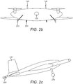
- Figure 2b and 2c respectively show front and side views of the vehicle. These figures show that the undercarriage orients the nose of the air vehicle in most cases at an angle of 10-45° upwards from the horizontal.
- Two rudders 140 are located at the rear of the vehicle to the upper side of the body. Both rudders 140 can be seen in figure 2b . One can be seen in figure 2c .
- Figure 2a shows the area of the wing planform and its low aspect-ratio can be clearly seen.
- the vehicle shown in figures 2a-2c has an aspect ratio in the range 0.5 to 2.0.
- the planform of the unmanned air vehicle of figures 2a-2c is derived from the Chance-Vought XF5U which was under development as a full scale fighter aircraft in the 1930s and 1940s.
- the Chance-Vought XF5U is shown in the photograph of figure 1a .
- Wind tunnel testing of a scale model of the XF5U is shown in the photographs of figures 1b and 1c .
- a largely disc-shaped planform would generally be thought to have very poor performance because of the small wing span.
- high pressure air below the wings could easily move around the end of the wing tip creating vortices above the wing. This causes drag and reduces lift.
- the propellers rotate in the opposite directions to the vortices counteracting their effect such that lift is maintained and drag is reduced.
- the vortices on the port and starboard sides of wing rotate in opposite directions, consequently the propellers rotate in opposite directions to counteract vortices at both sides of the wing.
- the unmanned air vehicle of figure 2 has a large payload volume capable of housing electric motors and a hybrid battery-fuel cell power system. A variety of cameras and sensors can also be mounted in the payload.
- the propellers are mounted significantly in front of (or above, when in hover mode) the body, for example at least the length of the propeller blades in front of the body. This configuration reduces interferences between propeller blades and the body on propeller start-up.
- the propellers are preferably folding propellers such that they can be folded down against the body to provide compactness during transit of the unmanned air vehicle to a launch site.
- the unmanned air vehicle preferably has two large rudders and two large ailevators to provide control during hover, horizontal flight and take-off and landing.
- the rudders 140 are built around a spar 205 extending through the rudder.
- the spar in each rudder is driven by a servo motor for rotation.
- the spar provides both structural rigidity and rotation drive to the rudder without requiring separate structures for each.
- the spar 205 of the rudders is shown in figures 7a and 7b .
- the rudder forms the whole of the vertical tail surface, and there is no fixed surface. The whole of the rudder rotates.
- a single rudder and two ailevators may be used, or more than two rudders and ailevators.
- the ailevators 130 shown in figures 2a and 2b form the widest extremes of the air vehicle. They extend laterally from the edges of the body. The ailevators are configured to rotate. Together the two ailevators have a length comparable to the width of the body.
- the rudders 140 may have a height similar to the length of the ailevators. Similarly to the rudders 140, the ailevators have structural rigidity provided by spars 208 which are also arranged for rotational drive. The spars 208 of the ailevators are shown in figures 7a and 7b .
- the propellers are driven by electric motors, with electricity generated by an on-board hybrid battery-fuel cell system.
- a primary camera or sensor 190 may be mounted at the front of the unmanned air vehicle for use during horizontal flight.
- the camera may collect imaging information during flight and may be gimbal mounted to maintain horizontal alignment as flight trajectory changes.
- the camera may also be mounted for driven rotation to direct the camera towards an area to be viewed.
- the camera may be a video camera operating in the visible spectrum, or may use other wavelengths of the electromagnetic spectrum.
- the camera may be an imaging sensor operating in the infra-red to collect temperature information.
- the camera or imaging sensor 190 may be mounted towards the front of the unmanned air vehicle. As shown in figure 2b and figure 4 the camera 190 may operate from the underside of the body. Alternatively the camera may be mounted for operation from the upper-side of the body. In both cases the field of view is limited by the position of the body. As discussed above, when the unmanned air vehicle operates in hover mode the body 100 is oriented vertically which changes the field of view of the camera. Furthermore, while it is useful to have a camera mounted for movement on the air vehicle, this camera may not have the resolution or may not operate in the desired part of the electromagnetic spectrum. Hence, it is desirable to provide alternative cameras arranged for operation when the body is oriented vertically during hover. Furthermore, these additional cameras may provide higher resolution or operate at a wavelengths more suited to the application.
- the unmanned air vehicle is equipped with a high definition camera 201 operating in the visible part of the spectrum and an infra-red camera 202.
- the infra-red camera 202 is adapted for monitoring faults in the power line. Such faults often exhibit a high temperature region as a result of a break, fracture or other resistive defect in the conductor in which heat is generated resulting in a "hot-spot".
- the type of infra-red camera may be selected that has sensors adapted for operation at wavelength appropriate for such "hot-spot" monitoring.
- the two additional cameras 201 and 202 are shown in figures 8 and 9 . These cameras are mounted either side of the main camera 190 towards the front of the air vehicle. However, the cameras 201 and 202 are mounted closer to the leading edge than the camera 190, and again may be mounted above or below. Preferably, they are mounted close enough to the leading edge that the leading edge does not obscure the field of view of the cameras.
- Figure 11 is a flow chart setting out steps of a method of inspection.
- the unmanned aircraft flies or cruises horizontally 410 and uses the main camera 190 which might be a video camera to inspect the power lines 420.
- the air vehicle would be oriented horizontally.
- the air vehicle would reduce its horizontal speed and transition to a hover mode 440 in which the body is oriented vertically, or close to vertical.
- the cameras or sensors 201 and 202 point upwards and, optionally, slightly forwards of the body towards the "hot-spot".
- the position of the aircraft 450 sets the direction of viewing of the cameras 201 and 202 without the need for gyroscopes or complex and heavy positioning actuators.
- the aircraft is flown in the vicinity of electrical towers or pylons. In particular, the aircraft may be flown below and to the side of the towers.
- Conventional UAVs performing the power line inspection task have a camera mounted on the underside of the vehicle. This necessitates flying the UAV above the power lines and electrical towers which could put at risk manned aircraft flying over the power lines and towers.
- the unmanned air vehicle described herein avoids the need to fly over the power lines and towers by being able to hover and by having the camera at the upper side of the vehicle during hover operations, and/or by having the camera pointing upwards during hover operations.
- a further camera 301 may be provided at the tail of the body as shown in figure 6 .
- the tail camera 301 may be used for imaging landing sites during vertical landings. In such landings the aircraft would likely have reduced its horizontal speed and transitioned to hover before landing. As discussed above, during hover the body of the vehicle is oriented vertically such that tail camera 301 points downwards.
- the tail camera images the ground for possible landing sites or generally images a landing area.
- the image data could be sent to a remote operator. Alternatively, the image data is sent to an on-board image processor 303 that uses pattern recognition to detect a known pattern identifying a landing site.
- the unmanned aerial vehicle is powered by electric motors from electricity supplied from an on-board hybrid battery-fuel cell system.
- the fuel cell part of the system produces electricity from hydrogen supplied from an on-board fuel tank and oxygen extracted from the atmosphere.
- the fuel cell system may comprise a cell stack comprising many cells stacked together to provide the required voltage and/or power.
- the fuel cell system is air-cooled by fans operating on the fuel cell or stack.
- the heated exhaust gases are warmer than the surrounding air and can be used to provide lift.
- fuel cells or a fuel cell stack 152 can be seen towards the front of the vehicle. Behind the fuel cell stack 152 is a fuel tank 150 containing hydrogen.
- the fuel cell or stack is cylindrical. At each end of the cylinder is a fan 154 for forcing air through the stack to cool the fuel cell.
- FIG. 10 shows a conduit 250 for guiding the exhaust air to the rear of the air vehicle such that at least some of the exhaust is blown over the upper surface of the flaps or ailevators.
- the fuel tank is generally much larger than the fuel cell or fuel cell stack so that the conduit 250 is arranged to guide the exhaust from the fuel cell, to the side of the fuel tank, and to the rear of the vehicle such that it leaves the vehicle over the ailevators.
- This arrangement is similar to the described in European Patent Application No. 12382165.4 by the same applicant.
- the blowing of the flaps or ailevators in this manner can also be used to correct any unsteady flight behaviour such as found in the XF5U.
- Figure 10 shows a single conduit guiding the exhaust from one side of the fuel cell (right hand side when viewed from above) to the ailevator on the same side of the air vehicle.
- a corresponding second conduit is arranged on the other side (left hand side) of the fuel cell to blow the ailevator on that side of the vehicle.
- a single conduit may be provided centrally along the aircraft and dividing at the rear to blow the ailevators.
- the air vehicle is provided with wheels and undercarriage or landing gear which orients the body, in most cases, at 10-45° to the ground.
- the undercarriage comprises four wheels.
- the first wheels 260 are rotationally coupled to mounts extending from the rear of the body.
- the two wheels 260 and mounts are laterally spaced along the rear edge of the body by approximately the same spacing as the rudders 140. This first pair of wheels provides ground clearance for the rear of the body.
- the second wheels 270 are provided extending from mounts towards the front of the body 100.
- the mounts for these two wheels are taller than those at the rear and extend at an angle diagonally sideways. The greater height of the mounts for the front wheels provides the, in most cases, 10-45° orientation to the body when on the ground.
- the undercarriage and wheels may be retractable into the body after take-off.
- the unmanned air vehicle may be provided with skids on the underside of the body for skid landings without the need for undercarriage.
- skid landings we mean landings in which the vehicle has horizontal velocity and so is not performing a vertical landing.
- the skids may form part of the skin of the body, such as for belly landings.
- Unmanned air vehicles without undercarriage or wheels have the advantage of reduced weight and drag penalties. Take-off may still require undercarriage to provide efficient forward movement, but the undercarriage may be ejected or released shortly after take-off.
- the aircraft may rest on an undercarriage dolly that is left on the ground after a sufficient lifting force is developed during a short take-off run.
- the present invention As set out above there are numerous differences between the present invention and the prior art XF5U.
- the original XF5U was proposed as a manned fighter aircraft.
- the present invention has removed the pilot canopy, as it is not required.
- the smoothed airflow over the upper surface of the body increases the stability in flight.
- the motor inlets shown at the front of the XF5U, between the propellers and the pilot canopy have also been removed. The removal of these features also acts to prevent boundary layer separation. Again this further stabilizes the aircraft during flight.
- the unmanned air vehicle had been developed and is particularly suited to monitoring and inspection activities.
- the monitoring and inspection activity may be power line inspection, for example electrical power lines carried overhead by towers, masts or pylons.
- the unmanned air vehicle could be adapted to monitor ground placed power lines.
- electrical cable, or gas or other fuel pipelines For example, electrical cable, or gas or other fuel pipelines.
- the unmanned air vehicle may also be used for monitoring critical infrastructure such as roads and railways. The flexibility to monitor different targets arises from the large payload bay size which provides space for a variety of camera and sensor to be mounted. This combined with high endurance makes the unmanned air vehicle flexible enough to be able to fly large distances and then hover to provide detailed monitoring a selected area or target.
- the unmanned air vehicle enables short/vertical take-off and landing (S/VTOL) capabilities in a long endurance 10kg class UAV.
- the expected endurance is five hours, with a speed range of between 45 and 100km/h in horizontal flight. In hover the endurance is 2.5 hours.
- the vehicle is modular and has a take-off weight of between 9 and 13 kg depending on specification for payloads between 400 and 800g.
- the lighter versions have extended endurance up to 6.5 hours.
- the present invention has the advantages of both VTOL and fixed wing air vehicles.
- VTOL operations are usually provided by helicopters but as shown above these lack adequate endurance and flight speeds.
- conventional fixed wing mini UAVs have too fast speed ranges that do not allow detailed spot inspection, and also required infrastructure for launch.
- the long endurance of the present invention allows single launch inspection of power lines over distances >100km.
- the external and some of the internal configuration of the air vehicle is shown in figure 2 .
- the air vehicle includes a 500W cruise or 800W peak power hybrid fuel cell system, which includes a lithium polymer (Li-Po) battery to deliver additional power during the take-off phase.
- Li-Po lithium polymer
- Previous wind tunnel testing relating to the prior art work on Zimmerman designs such as the XF5U provided aerodynamic data. This data in combination with the power available led to a 1.3m span size initially being chosen.
- Figure 3 shows efficiency curves for this configuration. Along the abscissa is shown the lift coefficient, CL. Along the ordinate are two parameters, CL/CD and CL 3/2 /CD, where CD is the drag coefficient. The parameter CL 3/2 /CD is a measure of efficiency.
- the span size results in a wing area of 1.25m 2 .
- L lift
- W aircraft take-off weight
- density of air 1.225 Kg/m 3 at 15°C
- S are of lifting surface
- the lift coefficient data in the figure results in a take-off weight of 13.5kg and a power consumption of 480W.
- the power system comprises two AXI 4120-20 brushless electrical motors. These are coupled to folding propellers, such as Graupner AEROCam 16"x8" (40cm x 20cm) in diameter and pitch. Electronic speed control of the motors is provided by Castle Creations Phoenix ICE Lite 75 Electronic Speed Controllers (ESC). In this configuration each propeller delivers up to 5kg in thrust. An optimum speed of horizontal flight is 76km/h and a top speed of 97km/h (at 15°C, 900m altitude) is provided. This configuration permits vertical take-off and hover for weights up to 9kg, allowing a safety margin. The use of folding propellers and electric motors is enough to overcome the vibration problems of the XF5U.
- folding propellers such as Graupner AEROCam 16"x8" (40cm x 20cm) in diameter and pitch.
- Electronic speed control of the motors is provided by Castle Creations Phoenix ICE Lite 75 Electronic Speed Controllers (ESC). In this configuration each propeller delivers
- the unmanned UAV includes different payload options.
- the primary option is that the main camera 190 is a gyro stabilized video camera, such as the TASE LT from Cloud Cap Technologies.
- a tail landing camera 301 could be used in combination with an image processor (such as board 303 in figure 6 ) to perform pattern recognition of landing sites. This method would allow landing at sites without the need for GPS or other external signals.
- the ailevators 130 and rudders 140 are built around torsion bars or spars 205 and 208 as shown in figures 7a and 7b . These spars as well as being structural are also driven using a 4 servo arrangement: one for each rudder and ailevator, to provide full ailevator and rudder control.
- the servos used are Giant Scale Futaba 9XXX servos.
- the unmanned air vehicle includes a housing for different hydrogen tank sizes.
- the housing is shown in figures 5 and 10 .
- the housing comprises a parallelepiped frame which couples to, or is part of, the airframe of the unmanned air vehicle.
- the hydrogen tank sits within a foam bed within the housing.
- Custom made foam beds can be used to adapt the housing to suit different sized fuel tanks without requiring adaption of the housing or airframe.
- payload vs fuel weights to be optimised such that for lighter payloads a smaller fuel tank is used because less fuel is expended for given mission.
- a lighter payload may mean the air vehicle can carry more fuel and be able to travel further before returning to a base location.
- Table 2 which follows summarizes the expected power consumption for different air vehicle weights. Endurance can be determined for different payload and filled fuel tank weights. Table 2: Power consumption versus unmanned air vehicle weights. Weight W (Kg) Lift L (N) Drag D (N) Cruise speed (km/h) Stall speed (km/h) Power P(Watts, elec, cruise) 9.2 90 4.1 80 38.1 273 11.2 110 5.0 88.5 42.2 369 13.3 130 5.9 96.4 45.9 476
- the numbers in bold in the final row of the table correspond with the simulated values based on aerodynamic data as mentioned above. That is, the weight is approximately 13.5kg and the power is approximately 480W.
- the first two columns relate to the fuel tank.
- the first column shows the weight of a fuel tank having a volume given in the second column.
- the third to fifth columns relate to total vehicle weight with various different payloads.
- the total weight includes the weight of the payload, the weight of the fuel tank and the weight of the rest of the vehicle.
- a 5 litre fuel tank and the TASE LT video camera have a total weight of 10.5-11.0 kg, with an endurance of almost five hours.
- Other tank configurations provide the following endurances given in table 4.
- Table 4 Endurance and take-off weight for various fuel tank volumes. Payload is TASE LT video camera. Tank volume (l) Endurance (hours) Take-off weight (kg) 2 2.6 9.2 5 4.9 11.0 6.8 6.2 11.5 9 6.7 13.0
- a 9 litre fuel tank is the maximum fuel tank size that can be used. Hover and vertical take-off cannot be achieved with such a large fuel tank.
- the values in table 4 are based on a payload of the TASE LT video camera only with gyro-stabilisation.
- high definition or infra-red cameras could be installed. Examples of these cameras are respectively the GoPro HERO HD camera which has a mass of 100g, and the FLIR TAU infra-red camera which has a mass of 75g.
- These two cameras could be used without a gimbal by flying the aircraft to direct the cameras at the target, such as the electrical cables or towers. In such an embodiment the aircraft would fly horizontally in the vicinity of the towers. The aircraft could be flown in the vicinity of the electrical towers and under the electrical cables with cameras pointing at least partly horizontally and/or upwards.
- the HD and infra-red cameras looking at least partly forward or upward, they could also be used to scan the skies to look for other aircraft to provide a forward-looking sense and avoid system.
- the vehicle Upon detection of an area requiring more detailed investigation, such as a hot spot, the vehicle can transition to hover mode with the body oriented vertically or pointing at least partly upward with the cameras or sensors also pointing upwards.
- a high definition and infra-red camera could be used in conjunction and could feed adapt to an image-processing board for onboard decision making, such as whether to continue taking more images of the hot-spot or whether to stop and continue along in horizontal flight.
- the unmanned air vehicle could be fitted with all three cameras (gimballed video camera such as TASE LT, fixed high definition camera, and infra-red camera) to have a take-off weight below 14 kg and still achieve an endurance of over 6 hours but with limited or no hover or high angle or attack capability.
- Gimballed video camera such as TASE LT, fixed high definition camera, and infra-red camera
Landscapes
- Engineering & Computer Science (AREA)
- Aviation & Aerospace Engineering (AREA)
- Mechanical Engineering (AREA)
- Chemical & Material Sciences (AREA)
- Combustion & Propulsion (AREA)
- Microelectronics & Electronic Packaging (AREA)
- Remote Sensing (AREA)
- Multimedia (AREA)
- Physics & Mathematics (AREA)
- General Physics & Mathematics (AREA)
- Signal Processing (AREA)
- Theoretical Computer Science (AREA)
- Control Of Position, Course, Altitude, Or Attitude Of Moving Bodies (AREA)
- Fuel Cell (AREA)
Claims (13)
- Unbemanntes Fluggerät, das für Schweben und kurzes / vertikales Starten und Landen (S/VTOL) geeignet ist, wobei das Fluggerät umfasst:einen Körper (100) mit einem Aspektverhältnis von weniger als zwei, wobei der Körper innen ein Nutzlastvolumen umfasst;zwei Propeller (120), von denen mindestens einer vor dem Körper angeordnet ist;mindestens ein Ruder (140) und mindestens zwei Klappen (130), die zur Rückseite des Körpers hin angeordnet sind; und eine erste Kamera (190),wobei der Körper angepasst ist, um Auftrieb bereitzustellen, wenn mit dem mindestens einen Propeller vor dem Körper Luft über den Körper strömt,wobei der Körper dadurch gekennzeichnet ist, dass er ferner so eingerichtet ist, dass das Fluggerät während des Schwebens und/oder des kurzen/vertikalen Starts und Landens (S/VTOL) wie ein Drehflügler arbeitet, wobei der Körper mit dem mindestens einen Propeller im Wesentlichen über dem Körper ausgerichtet ist,das Fluggerät so eingerichtet ist, dass der Körper während des horizontalen Fluges im Wesentlichen horizontal und beim Schweben im Wesentlichen vertikal ausgerichtet ist;die erste Kamera zur Bewegung am Fluggerät zur Verwendung während des Horizontalfluges montiert ist; undwobei das Fluggerät ferner zweite Kameras (201, 202) umfasst, die eingerichtet sind für den Betrieb, wenn der Körper während des Schwebens vertikal ausgerichtet ist, wobei die zweiten Kameras eine höhere Auflösung als die erste aufweisen.
- Unbemanntes Fluggerät nach Anspruch 1, bei dem der Körper beim kurzen/vertikalen Start und bei der Landung so ausgerichtet ist, dass das Fahrzeug teilweise als Drehflügler und teilweise als Starrflügelfluggerät arbeitet.
- Unbemanntes Fluggerät nach einem der vorhergehenden Ansprüche,
bei dem der Körper eine Zimmerman-Planform, eine inverse Zimmerman-Planform, eine quadratische oder rechteckige Planform oder eine kreisförmige oder elliptische Planform oder eine trapezförmige Planform symmetrisch zur Längsachse aufweist. - Unbemanntes Fluggerät nach einem der vorhergehenden Ansprüche,
bei dem bei dem der Körper ein Nur-Tragkörper ohne Rumpf-Flügel-Übergang ist. - Unbemanntes Fluggerät nach einem der vorhergehenden Ansprüche,
bei dem der mindestens eine Propeller an einer Gondel (110) montiert ist, die sich von dem Körper nach vorne erstreckt. - Unbemanntes Fluggerät nach einem der vorhergehenden Ansprüche,
mit mindestens zwei Propellern, die vor dem Körper angeordnet sind. - Unbemanntes Fluggerät nach einem der vorhergehenden Ansprüche, ferner mitmindestens einem Elektromotor zum Antreiben des mindestens einen Propellers;einer Brennstoffzelle (152) zum Erzeugen von Elektrizität zum Antreiben des mindestens einen Elektromotors; undeiner Abgasleitung (250) zum Führen des Brennstoffzellen-Abgases, um über die Klappen zu blasen.
- Unbemanntes Fluggerät nach einem der vorhergehenden Ansprüche, ferner miteiner weiteren Kamera (301), die an der Rückseite des Körpers angeordnet ist;einem mit der Kamera gekoppelten Bildprozessor; undeinem Leitsystem,wobei während einer kurzen/vertikalen Landung die Ausrichtung des Körpers die weitere Kamera nach unten richtet, der Bildprozessor Daten von der weiteren Kamera empfängt und einen Landeplatz identifiziert, und der Bildprozessor mit dem Leitsystem kommuniziert, um das unbemannte Fluggerät zu dem Landeplatz zu führen.
- Unbemanntes Fluggerät nach einem der vorhergehenden Ansprüche, ferner mit Unterkörperhautkufen für Rutsch- oder Bauchlandungen.
- Verfahren zum Betreiben eines unbemannten Fluggeräts, umfassend:Fliegen eines unbemannten Fluggeräts im Starrflüglermodus mit einem Propeller, der einen Vorwärtsantrieb bereitstellt; und nach dem Erfassen eines Zielbereichs, Anweisen des unbemannten Fluggeräts, zu schweben, wodurch das unbemannte Fluggerät seine Ausrichtung ändert und als Drehflügler arbeitet,wobei das Verfahren dadurch gekennzeichnet ist, dass der Schritt des Fliegens das Fliegen des unbemannten Fluggeräts im Starrflügelbetrieb in die Nähe eines zu untersuchenden Bereichs oder einer zu untersuchenden Struktur umfasst,wobei das Verfahren ferner das Sammeln von Bild- oder Sensordaten des Bereichs oder der Struktur mit einer Kamera oder einem Sensor des unbemannten Fluggeräts; undbeim Erkennen einer Zielzone, das Anweisen des unbemannten Fluggeräts, zu schweben, umfasst,wobei die Orientierungsänderung eine Kamera oder einen Sensor nach oben oder unten auf die Zielzone richtet und die Zielzone unter Verwendung einer höheren Auflösung als der im Horizontalflug verwendeten untersucht wird.
- Untersuchungsverfahren nach Anspruch 10, bei dem die Zielzone basierend auf den gesammelten Bild- oder Sensordaten des Bereichs oder der Struktur ausgewählt wird, wobei die Zielzone ein Teil des Bereichs oder der Struktur ist.
- Verfahren nach Anspruch 10 oder 11, bei dem das unbemannte Fluggerät das unbemannte Fluggerät nach einem der Ansprüche 1 bis 9 ist.
- Verfahren zum Untersuchen von Stromleitungen, umfassend das Verfahren nach einem der Ansprüche 10 bis 12, wobei die zu untersuchende Struktur eine Stromleitung ist und die Zielzone einen Fehler oder drohenden Fehler aufweist.
Priority Applications (5)
| Application Number | Priority Date | Filing Date | Title |
|---|---|---|---|
| EP14382029.8A EP2902319B1 (de) | 2014-01-30 | 2014-01-30 | Unbemanntes Luftfahrzeug |
| ES14382029T ES2746980T3 (es) | 2014-01-30 | 2014-01-30 | Vehículo aéreo no tripulado |
| CA2872028A CA2872028C (en) | 2014-01-30 | 2014-11-21 | Unmanned aerial vehicle |
| KR1020140173501A KR102252165B1 (ko) | 2014-01-30 | 2014-12-05 | 무인 항공기 |
| US14/608,014 US10589857B2 (en) | 2014-01-30 | 2015-01-28 | Unmanned aerial vehicle |
Applications Claiming Priority (1)
| Application Number | Priority Date | Filing Date | Title |
|---|---|---|---|
| EP14382029.8A EP2902319B1 (de) | 2014-01-30 | 2014-01-30 | Unbemanntes Luftfahrzeug |
Publications (2)
| Publication Number | Publication Date |
|---|---|
| EP2902319A1 EP2902319A1 (de) | 2015-08-05 |
| EP2902319B1 true EP2902319B1 (de) | 2019-06-26 |
Family
ID=50679981
Family Applications (1)
| Application Number | Title | Priority Date | Filing Date |
|---|---|---|---|
| EP14382029.8A Active EP2902319B1 (de) | 2014-01-30 | 2014-01-30 | Unbemanntes Luftfahrzeug |
Country Status (5)
| Country | Link |
|---|---|
| US (1) | US10589857B2 (de) |
| EP (1) | EP2902319B1 (de) |
| KR (1) | KR102252165B1 (de) |
| CA (1) | CA2872028C (de) |
| ES (1) | ES2746980T3 (de) |
Families Citing this family (58)
| Publication number | Priority date | Publication date | Assignee | Title |
|---|---|---|---|---|
| US8818572B1 (en) * | 2013-03-15 | 2014-08-26 | State Farm Mutual Automobile Insurance Company | System and method for controlling a remote aerial device for up-close inspection |
| US9428056B2 (en) | 2014-03-11 | 2016-08-30 | Textron Innovations, Inc. | Adjustable synthetic vision |
| US10347140B2 (en) | 2014-03-11 | 2019-07-09 | Textron Innovations Inc. | Flight planning and communication |
| US10042456B2 (en) | 2014-03-11 | 2018-08-07 | Textron Innovations Inc. | User interface for an aircraft |
| US10005562B2 (en) | 2014-03-11 | 2018-06-26 | Textron Innovations Inc. | Standby instrument panel for aircraft |
| WO2015138327A1 (en) * | 2014-03-11 | 2015-09-17 | Cessna Aircraft Company | Touch screen instrument panel |
| WO2016065626A1 (zh) * | 2014-10-31 | 2016-05-06 | 深圳市大疆创新科技有限公司 | 一种气体泄漏的处理方法、装置及飞行器 |
| US20160246297A1 (en) * | 2015-02-24 | 2016-08-25 | Siemens Corporation | Cloud-based control system for unmanned aerial vehicles |
| CN112722300A (zh) | 2015-04-21 | 2021-04-30 | 高途乐公司 | 空中捕获平台 |
| US10696414B2 (en) | 2015-04-21 | 2020-06-30 | Gopro, Inc. | Aerial capture platform |
| USD768539S1 (en) * | 2015-08-04 | 2016-10-11 | Gopro, Inc. | Aerial vehicle |
| USD803328S1 (en) | 2015-12-18 | 2017-11-21 | Gopro, Inc. | Aerial vehicle |
| US12221237B2 (en) | 2015-04-21 | 2025-02-11 | Gopro, Inc. | Unmanned aerial vehicle with rotating and overlapping rotor arms |
| US10029804B1 (en) | 2015-05-14 | 2018-07-24 | Near Earth Autonomy, Inc. | On-board, computerized landing zone evaluation system for aircraft |
| CN105486346B (zh) * | 2015-12-17 | 2016-10-05 | 国网山东省电力公司昌乐县供电公司 | 高压线路环境参数采集报警平台 |
| CN105644785B (zh) * | 2015-12-31 | 2017-06-27 | 哈尔滨工业大学 | 一种基于光流法和地平线检测的无人机着陆方法 |
| US10086956B2 (en) * | 2016-01-27 | 2018-10-02 | Amazon Technologies, Inc. | Light adjustment control for cameras of an aerial vehicle |
| US10168700B2 (en) * | 2016-02-11 | 2019-01-01 | International Business Machines Corporation | Control of an aerial drone using recognized gestures |
| US10723440B2 (en) * | 2016-03-23 | 2020-07-28 | Amazon Technologies, Inc. | Aerial vehicle with different propeller blade configurations |
| US10526070B2 (en) | 2016-03-23 | 2020-01-07 | Amazon Technologies, Inc. | Aerial vehicle propulsion mechanism with coaxially aligned propellers |
| US11305874B2 (en) | 2016-03-23 | 2022-04-19 | Amazon Technologies, Inc. | Aerial vehicle adaptable propeller blades |
| US10583914B2 (en) | 2016-03-23 | 2020-03-10 | Amazon Technologies, Inc. | Telescoping propeller blades for aerial vehicles |
| US10399666B2 (en) | 2016-03-23 | 2019-09-03 | Amazon Technologies, Inc. | Aerial vehicle propulsion mechanism with coaxially aligned and independently rotatable propellers |
| CN105977863B (zh) * | 2016-06-08 | 2018-09-11 | 国网甘肃省电力公司检修公司 | 输电线路无人机抛绳停电及带电检修作业方法 |
| CN106356757B (zh) * | 2016-08-11 | 2018-03-20 | 河海大学常州校区 | 一种基于人眼视觉特性的电力线路无人机巡检方法 |
| KR101806261B1 (ko) * | 2016-10-17 | 2017-12-07 | 하이리움산업(주) | 연료탱크 장착부를 포함하는 멀티콥터 |
| US10562623B1 (en) | 2016-10-21 | 2020-02-18 | Birdseyeview Aerobotics, Llc | Remotely controlled VTOL aircraft |
| WO2018080425A1 (en) * | 2016-10-24 | 2018-05-03 | Ford Global Technologies, Llc | Using unmanned aerial vehicles to inspect autonomous vehicles |
| US11195132B2 (en) | 2016-10-31 | 2021-12-07 | International Business Machines Corporation | System, method and computer program product for characterizing object status and determining a maintenance schedule |
| CN106741942B (zh) * | 2016-12-20 | 2018-12-07 | 西安交通大学 | 一种用于高压输电线路巡检的仿生两运动模态机器人 |
| US11017679B2 (en) * | 2017-01-13 | 2021-05-25 | Skydio, Inc. | Unmanned aerial vehicle visual point cloud navigation |
| EP3376213B1 (de) * | 2017-03-15 | 2025-11-12 | Siemens Energy Global GmbH & Co. KG | Verfahren und anordnung für eine zustandsüberwachung einer anlage mit betriebsmitteln |
| US10977880B2 (en) * | 2017-05-31 | 2021-04-13 | General Electric Company | Hover time remaining for an aircraft |
| KR101879673B1 (ko) * | 2017-06-02 | 2018-07-18 | (주)건설표준시험원 | 무인 비행체를 이용한 구조물 표면 조사 장치 및 방법 |
| CN107168370A (zh) * | 2017-06-16 | 2017-09-15 | 广东电网有限责任公司佛山供电局 | 输电线路多旋翼无人机精细智能巡检系统及其方法 |
| FR3071817B1 (fr) * | 2017-09-29 | 2019-09-27 | Airbus Helicopters | Drone comportant au moins un moteur electrique de propulsion et une source d'energie de type pile a combustible |
| CN107769077A (zh) * | 2017-11-13 | 2018-03-06 | 国家电网公司 | 一种基于多功能底座的输电线路带电作业无人机 |
| MA41573B1 (fr) * | 2017-12-06 | 2019-12-31 | Univ Int Rabat | Fixation mécanique pour train d'atterrissage détachable |
| US12043377B2 (en) * | 2018-01-30 | 2024-07-23 | Joseph Raymond RENTERIA | Rotatable thruster aircraft |
| CN108415456A (zh) * | 2018-02-23 | 2018-08-17 | 华南理工大学 | 一种飞滑式机器人自动越障装置和越障方法 |
| RU185829U1 (ru) * | 2018-04-18 | 2018-12-19 | Александр Александрович Горбунов | Самолет вертикального взлета и посадки с эллипсным(дисковым) крылом |
| CN108599076A (zh) * | 2018-06-11 | 2018-09-28 | 贵州电网有限责任公司 | 一种用于输电线路的无人机抛绳器及其使用方法 |
| EP3614155A1 (de) * | 2018-08-22 | 2020-02-26 | Siemens Aktiengesellschaft | Verfahren und anordnung zum erkennen von koronaentladungen einer anlage mit betriebsmitteln |
| KR102134965B1 (ko) * | 2018-08-31 | 2020-07-16 | (주)두산 모빌리티 이노베이션 | 연료전지 파워팩 일체형 드론의 가스탱크 장탈착 틸팅 및 가스 공급 구조 |
| CN109460054A (zh) * | 2018-09-11 | 2019-03-12 | 成都优艾维智能科技有限责任公司 | 一种针对直流单回耐张塔的无人机自主巡检方法 |
| US10611479B1 (en) * | 2019-01-18 | 2020-04-07 | Bell Textron Inc. | Inset turret assemblies for aircraft |
| US10972649B2 (en) | 2019-02-27 | 2021-04-06 | X Development Llc | Infrared and visible imaging system for device identification and tracking |
| CN110361984B (zh) * | 2019-06-25 | 2021-01-26 | 电子科技大学 | 一种增加阻力的交叉舵耗能方法 |
| US11675324B2 (en) * | 2019-09-19 | 2023-06-13 | Bao Tran | Air transportation systems and methods |
| CN110635393A (zh) * | 2019-10-25 | 2019-12-31 | 江苏电卫士电力服务有限公司 | 一种电力巡检系统 |
| CN110829271B (zh) * | 2019-12-11 | 2021-02-26 | 云南电网有限责任公司红河供电局 | 输电线路缺陷巡检装置及缺陷分析方法 |
| CN111152919B (zh) * | 2020-01-08 | 2021-06-15 | 北京建筑大学 | 一种可垂直起降的无人机的控制方法 |
| CN112848926A (zh) * | 2021-03-01 | 2021-05-28 | 国网冀北电力有限公司唐山供电公司 | 一种用于线路检修的巡逻装置及其使用方法 |
| CN113394707B (zh) * | 2021-05-25 | 2022-05-24 | 杭州申昊科技股份有限公司 | 一种基于无人机的输电线巡检机器人 |
| CN116466734B (zh) * | 2023-05-04 | 2024-02-06 | 山东御航智能科技有限公司 | 无人机穿线方法及系统 |
| US20240400214A1 (en) * | 2023-06-05 | 2024-12-05 | Pipistrel D.O.O. | Exhaust Airflow System |
| TWI903188B (zh) * | 2023-07-11 | 2025-11-01 | 佳世達科技股份有限公司 | 無人機 |
| WO2025080596A1 (en) * | 2023-10-08 | 2025-04-17 | OneSec, Inc. | Unmanned aerial vehicle and landing system |
Family Cites Families (22)
| Publication number | Priority date | Publication date | Assignee | Title |
|---|---|---|---|---|
| US3161374A (en) | 1962-10-22 | 1964-12-15 | Boeing Co | Vertical lift aircraft |
| FR2804936B1 (fr) * | 2000-02-15 | 2002-06-07 | Bertin Technologies Sa | Engin volant telecommande, en particulier de surveillance ou d'inspection |
| US7543780B1 (en) * | 2004-10-04 | 2009-06-09 | The United States Of America As Represented By The Secretary Of The Air Force | Unmanned air vehicle transmission line docking surveillance |
| WO2006073750A2 (en) | 2004-12-17 | 2006-07-13 | James Alman | Stowable design for unmanned aerial vehicle |
| US7159817B2 (en) | 2005-01-13 | 2007-01-09 | Vandermey Timothy | Vertical take-off and landing (VTOL) aircraft with distributed thrust and control |
| US7264204B1 (en) | 2005-12-12 | 2007-09-04 | The United States Of America As Represented By The Secretary Of The Navy | Unmanned aerial vehicle catcher |
| US7510142B2 (en) | 2006-02-24 | 2009-03-31 | Stealth Robotics | Aerial robot |
| US20070215751A1 (en) | 2006-03-20 | 2007-09-20 | Robbins Brent A | Asymmetrical VTOL UAV |
| US7410122B2 (en) | 2006-03-20 | 2008-08-12 | The Boeing Company | VTOL UAV with lift fans in joined wings |
| US7699261B2 (en) | 2007-03-05 | 2010-04-20 | Lockheed Martin Corporation | Small unmanned airborne vehicle airframe |
| WO2008130402A2 (en) | 2007-04-19 | 2008-10-30 | Sikorsky Aircraft Corporation | Winch system for vtol aircraft |
| US7871044B2 (en) | 2007-05-23 | 2011-01-18 | Honeywell International Inc. | Method for vertical takeoff from and landing on inclined surfaces |
| DE102008019146A1 (de) * | 2008-04-16 | 2009-11-05 | Airbus Deutschland Gmbh | Enteisungssystem für ein Flugzeug |
| US8172177B2 (en) | 2008-06-02 | 2012-05-08 | Advanced Technology & Research Corp. | Stabilized UAV recovery system |
| US8328130B2 (en) | 2008-12-08 | 2012-12-11 | Honeywell International Inc. | Vertical take off and landing unmanned aerial vehicle airframe structure |
| IL195977A (en) * | 2008-12-16 | 2013-12-31 | Abraham Abershitz | An unmanned aerial vehicle with an improved aerodynamic configuration |
| US8500067B2 (en) * | 2009-09-09 | 2013-08-06 | Aurora Flight Sciences Corporation | Modular miniature unmanned aircraft with vectored-thrust control |
| GB0920636D0 (en) * | 2009-11-25 | 2010-01-13 | Cyberhawk Innovations Ltd | Unmanned aerial vehicle |
| WO2011163143A1 (en) | 2010-06-21 | 2011-12-29 | Optimal Ranging, Inc. | Uav power line position and load parameter estimation |
| US9004393B2 (en) * | 2010-10-24 | 2015-04-14 | University Of Kansas | Supersonic hovering air vehicle |
| EP2660147B1 (de) | 2012-05-04 | 2017-09-27 | The Boeing Company | Unbemanntes Luftfahrzeug (UAS) |
| US8996207B2 (en) * | 2013-06-24 | 2015-03-31 | Honeywell International Inc. | Systems and methods for autonomous landing using a three dimensional evidence grid |
-
2014
- 2014-01-30 EP EP14382029.8A patent/EP2902319B1/de active Active
- 2014-01-30 ES ES14382029T patent/ES2746980T3/es active Active
- 2014-11-21 CA CA2872028A patent/CA2872028C/en active Active
- 2014-12-05 KR KR1020140173501A patent/KR102252165B1/ko active Active
-
2015
- 2015-01-28 US US14/608,014 patent/US10589857B2/en active Active
Non-Patent Citations (1)
| Title |
|---|
| None * |
Also Published As
| Publication number | Publication date |
|---|---|
| EP2902319A1 (de) | 2015-08-05 |
| KR20150090992A (ko) | 2015-08-07 |
| CA2872028C (en) | 2018-04-03 |
| US20150210388A1 (en) | 2015-07-30 |
| US10589857B2 (en) | 2020-03-17 |
| ES2746980T3 (es) | 2020-03-09 |
| KR102252165B1 (ko) | 2021-05-14 |
| CA2872028A1 (en) | 2015-07-30 |
Similar Documents
| Publication | Publication Date | Title |
|---|---|---|
| EP2902319B1 (de) | Unbemanntes Luftfahrzeug | |
| US10717522B2 (en) | Vertical takeoff and landing (VTOL) air vehicle | |
| US9120560B1 (en) | Vertical take-off and landing aircraft | |
| US10538321B2 (en) | Tri-rotor aircraft capable of vertical takeoff and landing and transitioning to forward flight | |
| US8434710B2 (en) | Aircraft | |
| US9096314B2 (en) | Electric VTOL aircraft | |
| CN105473443B (zh) | 采用新空气动力和技术方案的多用途且安全的垂直起降飞机 | |
| CN103796917B (zh) | 个人飞机 | |
| US8733690B2 (en) | Lightweight vertical take-off and landing aircraft and flight control paradigm using thrust differentials | |
| EP3087003B1 (de) | Unbemanntes luftfahrzeug | |
| US20150344134A1 (en) | High Performance VTOL Aircraft | |
| CN116034075A (zh) | 一种垂直起降飞机,用于控制垂直起降飞机的方法和系统 | |
| US20130264429A1 (en) | Convertible airplane | |
| NL1040979B1 (en) | Air vehicle. |
Legal Events
| Date | Code | Title | Description |
|---|---|---|---|
| PUAI | Public reference made under article 153(3) epc to a published international application that has entered the european phase |
Free format text: ORIGINAL CODE: 0009012 |
|
| 17P | Request for examination filed |
Effective date: 20140130 |
|
| AK | Designated contracting states |
Kind code of ref document: A1 Designated state(s): AL AT BE BG CH CY CZ DE DK EE ES FI FR GB GR HR HU IE IS IT LI LT LU LV MC MK MT NL NO PL PT RO RS SE SI SK SM TR |
|
| AX | Request for extension of the european patent |
Extension state: BA ME |
|
| GRAP | Despatch of communication of intention to grant a patent |
Free format text: ORIGINAL CODE: EPIDOSNIGR1 |
|
| STAA | Information on the status of an ep patent application or granted ep patent |
Free format text: STATUS: GRANT OF PATENT IS INTENDED |
|
| INTG | Intention to grant announced |
Effective date: 20190116 |
|
| GRAS | Grant fee paid |
Free format text: ORIGINAL CODE: EPIDOSNIGR3 |
|
| GRAA | (expected) grant |
Free format text: ORIGINAL CODE: 0009210 |
|
| STAA | Information on the status of an ep patent application or granted ep patent |
Free format text: STATUS: THE PATENT HAS BEEN GRANTED |
|
| AK | Designated contracting states |
Kind code of ref document: B1 Designated state(s): AL AT BE BG CH CY CZ DE DK EE ES FI FR GB GR HR HU IE IS IT LI LT LU LV MC MK MT NL NO PL PT RO RS SE SI SK SM TR |
|
| REG | Reference to a national code |
Ref country code: GB Ref legal event code: FG4D |
|
| REG | Reference to a national code |
Ref country code: CH Ref legal event code: EP |
|
| REG | Reference to a national code |
Ref country code: AT Ref legal event code: REF Ref document number: 1147995 Country of ref document: AT Kind code of ref document: T Effective date: 20190715 |
|
| REG | Reference to a national code |
Ref country code: DE Ref legal event code: R096 Ref document number: 602014049013 Country of ref document: DE |
|
| REG | Reference to a national code |
Ref country code: IE Ref legal event code: FG4D |
|
| REG | Reference to a national code |
Ref country code: NL Ref legal event code: MP Effective date: 20190626 |
|
| PG25 | Lapsed in a contracting state [announced via postgrant information from national office to epo] |
Ref country code: FI Free format text: LAPSE BECAUSE OF FAILURE TO SUBMIT A TRANSLATION OF THE DESCRIPTION OR TO PAY THE FEE WITHIN THE PRESCRIBED TIME-LIMIT Effective date: 20190626 Ref country code: LT Free format text: LAPSE BECAUSE OF FAILURE TO SUBMIT A TRANSLATION OF THE DESCRIPTION OR TO PAY THE FEE WITHIN THE PRESCRIBED TIME-LIMIT Effective date: 20190626 Ref country code: HR Free format text: LAPSE BECAUSE OF FAILURE TO SUBMIT A TRANSLATION OF THE DESCRIPTION OR TO PAY THE FEE WITHIN THE PRESCRIBED TIME-LIMIT Effective date: 20190626 Ref country code: NO Free format text: LAPSE BECAUSE OF FAILURE TO SUBMIT A TRANSLATION OF THE DESCRIPTION OR TO PAY THE FEE WITHIN THE PRESCRIBED TIME-LIMIT Effective date: 20190926 Ref country code: AL Free format text: LAPSE BECAUSE OF FAILURE TO SUBMIT A TRANSLATION OF THE DESCRIPTION OR TO PAY THE FEE WITHIN THE PRESCRIBED TIME-LIMIT Effective date: 20190626 Ref country code: SE Free format text: LAPSE BECAUSE OF FAILURE TO SUBMIT A TRANSLATION OF THE DESCRIPTION OR TO PAY THE FEE WITHIN THE PRESCRIBED TIME-LIMIT Effective date: 20190626 |
|
| REG | Reference to a national code |
Ref country code: LT Ref legal event code: MG4D |
|
| PG25 | Lapsed in a contracting state [announced via postgrant information from national office to epo] |
Ref country code: LV Free format text: LAPSE BECAUSE OF FAILURE TO SUBMIT A TRANSLATION OF THE DESCRIPTION OR TO PAY THE FEE WITHIN THE PRESCRIBED TIME-LIMIT Effective date: 20190626 Ref country code: GR Free format text: LAPSE BECAUSE OF FAILURE TO SUBMIT A TRANSLATION OF THE DESCRIPTION OR TO PAY THE FEE WITHIN THE PRESCRIBED TIME-LIMIT Effective date: 20190927 Ref country code: RS Free format text: LAPSE BECAUSE OF FAILURE TO SUBMIT A TRANSLATION OF THE DESCRIPTION OR TO PAY THE FEE WITHIN THE PRESCRIBED TIME-LIMIT Effective date: 20190626 Ref country code: BG Free format text: LAPSE BECAUSE OF FAILURE TO SUBMIT A TRANSLATION OF THE DESCRIPTION OR TO PAY THE FEE WITHIN THE PRESCRIBED TIME-LIMIT Effective date: 20190926 |
|
| REG | Reference to a national code |
Ref country code: DE Ref legal event code: R082 Ref document number: 602014049013 Country of ref document: DE Representative=s name: MAIER, LL.M., MICHAEL C., DE Ref country code: DE Ref legal event code: R082 Ref document number: 602014049013 Country of ref document: DE Representative=s name: BOULT WADE TENNANT LLP, DE |
|
| REG | Reference to a national code |
Ref country code: AT Ref legal event code: MK05 Ref document number: 1147995 Country of ref document: AT Kind code of ref document: T Effective date: 20190626 |
|
| PG25 | Lapsed in a contracting state [announced via postgrant information from national office to epo] |
Ref country code: RO Free format text: LAPSE BECAUSE OF FAILURE TO SUBMIT A TRANSLATION OF THE DESCRIPTION OR TO PAY THE FEE WITHIN THE PRESCRIBED TIME-LIMIT Effective date: 20190626 Ref country code: CZ Free format text: LAPSE BECAUSE OF FAILURE TO SUBMIT A TRANSLATION OF THE DESCRIPTION OR TO PAY THE FEE WITHIN THE PRESCRIBED TIME-LIMIT Effective date: 20190626 Ref country code: SK Free format text: LAPSE BECAUSE OF FAILURE TO SUBMIT A TRANSLATION OF THE DESCRIPTION OR TO PAY THE FEE WITHIN THE PRESCRIBED TIME-LIMIT Effective date: 20190626 Ref country code: PT Free format text: LAPSE BECAUSE OF FAILURE TO SUBMIT A TRANSLATION OF THE DESCRIPTION OR TO PAY THE FEE WITHIN THE PRESCRIBED TIME-LIMIT Effective date: 20191028 Ref country code: AT Free format text: LAPSE BECAUSE OF FAILURE TO SUBMIT A TRANSLATION OF THE DESCRIPTION OR TO PAY THE FEE WITHIN THE PRESCRIBED TIME-LIMIT Effective date: 20190626 Ref country code: NL Free format text: LAPSE BECAUSE OF FAILURE TO SUBMIT A TRANSLATION OF THE DESCRIPTION OR TO PAY THE FEE WITHIN THE PRESCRIBED TIME-LIMIT Effective date: 20190626 Ref country code: EE Free format text: LAPSE BECAUSE OF FAILURE TO SUBMIT A TRANSLATION OF THE DESCRIPTION OR TO PAY THE FEE WITHIN THE PRESCRIBED TIME-LIMIT Effective date: 20190626 |
|
| REG | Reference to a national code |
Ref country code: DE Ref legal event code: R082 Ref document number: 602014049013 Country of ref document: DE Representative=s name: BOULT WADE TENNANT LLP, DE |
|
| PG25 | Lapsed in a contracting state [announced via postgrant information from national office to epo] |
Ref country code: SM Free format text: LAPSE BECAUSE OF FAILURE TO SUBMIT A TRANSLATION OF THE DESCRIPTION OR TO PAY THE FEE WITHIN THE PRESCRIBED TIME-LIMIT Effective date: 20190626 Ref country code: IS Free format text: LAPSE BECAUSE OF FAILURE TO SUBMIT A TRANSLATION OF THE DESCRIPTION OR TO PAY THE FEE WITHIN THE PRESCRIBED TIME-LIMIT Effective date: 20191026 |
|
| REG | Reference to a national code |
Ref country code: ES Ref legal event code: FG2A Ref document number: 2746980 Country of ref document: ES Kind code of ref document: T3 Effective date: 20200309 |
|
| PG25 | Lapsed in a contracting state [announced via postgrant information from national office to epo] |
Ref country code: TR Free format text: LAPSE BECAUSE OF FAILURE TO SUBMIT A TRANSLATION OF THE DESCRIPTION OR TO PAY THE FEE WITHIN THE PRESCRIBED TIME-LIMIT Effective date: 20190626 |
|
| PG25 | Lapsed in a contracting state [announced via postgrant information from national office to epo] |
Ref country code: DK Free format text: LAPSE BECAUSE OF FAILURE TO SUBMIT A TRANSLATION OF THE DESCRIPTION OR TO PAY THE FEE WITHIN THE PRESCRIBED TIME-LIMIT Effective date: 20190626 Ref country code: PL Free format text: LAPSE BECAUSE OF FAILURE TO SUBMIT A TRANSLATION OF THE DESCRIPTION OR TO PAY THE FEE WITHIN THE PRESCRIBED TIME-LIMIT Effective date: 20190626 |
|
| PG25 | Lapsed in a contracting state [announced via postgrant information from national office to epo] |
Ref country code: IS Free format text: LAPSE BECAUSE OF FAILURE TO SUBMIT A TRANSLATION OF THE DESCRIPTION OR TO PAY THE FEE WITHIN THE PRESCRIBED TIME-LIMIT Effective date: 20200224 |
|
| REG | Reference to a national code |
Ref country code: DE Ref legal event code: R097 Ref document number: 602014049013 Country of ref document: DE |
|
| PLBE | No opposition filed within time limit |
Free format text: ORIGINAL CODE: 0009261 |
|
| STAA | Information on the status of an ep patent application or granted ep patent |
Free format text: STATUS: NO OPPOSITION FILED WITHIN TIME LIMIT |
|
| PG2D | Information on lapse in contracting state deleted |
Ref country code: IS |
|
| 26N | No opposition filed |
Effective date: 20200603 |
|
| PG25 | Lapsed in a contracting state [announced via postgrant information from national office to epo] |
Ref country code: MC Free format text: LAPSE BECAUSE OF FAILURE TO SUBMIT A TRANSLATION OF THE DESCRIPTION OR TO PAY THE FEE WITHIN THE PRESCRIBED TIME-LIMIT Effective date: 20190626 Ref country code: SI Free format text: LAPSE BECAUSE OF FAILURE TO SUBMIT A TRANSLATION OF THE DESCRIPTION OR TO PAY THE FEE WITHIN THE PRESCRIBED TIME-LIMIT Effective date: 20190626 |
|
| REG | Reference to a national code |
Ref country code: CH Ref legal event code: PL |
|
| REG | Reference to a national code |
Ref country code: BE Ref legal event code: MM Effective date: 20200131 |
|
| PG25 | Lapsed in a contracting state [announced via postgrant information from national office to epo] |
Ref country code: LU Free format text: LAPSE BECAUSE OF NON-PAYMENT OF DUE FEES Effective date: 20200130 |
|
| PG25 | Lapsed in a contracting state [announced via postgrant information from national office to epo] |
Ref country code: CH Free format text: LAPSE BECAUSE OF NON-PAYMENT OF DUE FEES Effective date: 20200131 Ref country code: LI Free format text: LAPSE BECAUSE OF NON-PAYMENT OF DUE FEES Effective date: 20200131 Ref country code: BE Free format text: LAPSE BECAUSE OF NON-PAYMENT OF DUE FEES Effective date: 20200131 |
|
| PG25 | Lapsed in a contracting state [announced via postgrant information from national office to epo] |
Ref country code: IE Free format text: LAPSE BECAUSE OF NON-PAYMENT OF DUE FEES Effective date: 20200130 |
|
| PG25 | Lapsed in a contracting state [announced via postgrant information from national office to epo] |
Ref country code: MT Free format text: LAPSE BECAUSE OF FAILURE TO SUBMIT A TRANSLATION OF THE DESCRIPTION OR TO PAY THE FEE WITHIN THE PRESCRIBED TIME-LIMIT Effective date: 20190626 Ref country code: CY Free format text: LAPSE BECAUSE OF FAILURE TO SUBMIT A TRANSLATION OF THE DESCRIPTION OR TO PAY THE FEE WITHIN THE PRESCRIBED TIME-LIMIT Effective date: 20190626 |
|
| PG25 | Lapsed in a contracting state [announced via postgrant information from national office to epo] |
Ref country code: MK Free format text: LAPSE BECAUSE OF FAILURE TO SUBMIT A TRANSLATION OF THE DESCRIPTION OR TO PAY THE FEE WITHIN THE PRESCRIBED TIME-LIMIT Effective date: 20190626 |
|
| P01 | Opt-out of the competence of the unified patent court (upc) registered |
Effective date: 20230516 |
|
| PGFP | Annual fee paid to national office [announced via postgrant information from national office to epo] |
Ref country code: GB Payment date: 20260127 Year of fee payment: 13 |
|
| PGFP | Annual fee paid to national office [announced via postgrant information from national office to epo] |
Ref country code: ES Payment date: 20260202 Year of fee payment: 13 |
|
| PGFP | Annual fee paid to national office [announced via postgrant information from national office to epo] |
Ref country code: DE Payment date: 20260128 Year of fee payment: 13 |
|
| PGFP | Annual fee paid to national office [announced via postgrant information from national office to epo] |
Ref country code: IT Payment date: 20260121 Year of fee payment: 13 |
|
| PGFP | Annual fee paid to national office [announced via postgrant information from national office to epo] |
Ref country code: FR Payment date: 20260126 Year of fee payment: 13 |