EP2902566A2 - Montants de balustrades, rampes et similaires - Google Patents
Montants de balustrades, rampes et similaires Download PDFInfo
- Publication number
- EP2902566A2 EP2902566A2 EP15153120.9A EP15153120A EP2902566A2 EP 2902566 A2 EP2902566 A2 EP 2902566A2 EP 15153120 A EP15153120 A EP 15153120A EP 2902566 A2 EP2902566 A2 EP 2902566A2
- Authority
- EP
- European Patent Office
- Prior art keywords
- post
- tubular body
- handrail
- post according
- cavity
- Prior art date
- Legal status (The legal status is an assumption and is not a legal conclusion. Google has not performed a legal analysis and makes no representation as to the accuracy of the status listed.)
- Granted
Links
- 238000003780 insertion Methods 0.000 claims description 4
- 230000037431 insertion Effects 0.000 claims description 4
- 230000001681 protective effect Effects 0.000 description 5
- 238000009434 installation Methods 0.000 description 4
- 239000000463 material Substances 0.000 description 4
- 239000010935 stainless steel Substances 0.000 description 3
- 229910001220 stainless steel Inorganic materials 0.000 description 3
- 238000003754 machining Methods 0.000 description 2
- 230000001154 acute effect Effects 0.000 description 1
- 230000008878 coupling Effects 0.000 description 1
- 238000010168 coupling process Methods 0.000 description 1
- 238000005859 coupling reaction Methods 0.000 description 1
- 230000001419 dependent effect Effects 0.000 description 1
- 238000005516 engineering process Methods 0.000 description 1
- 230000010006 flight Effects 0.000 description 1
- 230000004927 fusion Effects 0.000 description 1
- 238000004519 manufacturing process Methods 0.000 description 1
- 229910001092 metal group alloy Inorganic materials 0.000 description 1
- 238000000465 moulding Methods 0.000 description 1
- 230000000284 resting effect Effects 0.000 description 1
- 238000003860 storage Methods 0.000 description 1
Images



Classifications
-
- E—FIXED CONSTRUCTIONS
- E04—BUILDING
- E04F—FINISHING WORK ON BUILDINGS, e.g. STAIRS, FLOORS
- E04F11/00—Stairways, ramps, or like structures; Balustrades; Handrails
- E04F11/18—Balustrades; Handrails
- E04F11/181—Balustrades
- E04F11/1817—Connections therefor
- E04F11/1834—Connections therefor with adjustable angle, e.g. pivotal connections
-
- E—FIXED CONSTRUCTIONS
- E04—BUILDING
- E04F—FINISHING WORK ON BUILDINGS, e.g. STAIRS, FLOORS
- E04F11/00—Stairways, ramps, or like structures; Balustrades; Handrails
- E04F11/18—Balustrades; Handrails
- E04F11/181—Balustrades
- E04F11/1812—Details of anchoring to the wall or floor
-
- E—FIXED CONSTRUCTIONS
- E04—BUILDING
- E04F—FINISHING WORK ON BUILDINGS, e.g. STAIRS, FLOORS
- E04F11/00—Stairways, ramps, or like structures; Balustrades; Handrails
- E04F11/18—Balustrades; Handrails
- E04F11/181—Balustrades
- E04F11/1817—Connections therefor
- E04F2011/1819—Connections therefor between balustrade posts and horizontal or sloping balustrade members
- E04F2011/1821—Connections therefor between balustrade posts and horizontal or sloping balustrade members between balustrade posts and handrails
Definitions
- the present invention concerns a post for balusters, railings and similar.
- the most common banisters and railings are made entirely from metallic components, for example made from stainless steel or other materials having suitable characteristics both in terms of appearance and in terms of function.
- the technical task of the present invention is therefore that of improving the state of the art.
- a purpose of the present invention is to devise a post that makes it possibly to easily adjust the inclination of the handrail, with angular excursion greater than that of known posts.
- Yet another purpose of the present invention is to make a post characterised by a connection to the handrail of a banister, or other protective structure, having limited bulk and therefore that is more functional.
- the post according to the invention comprises a tubular body, provided with a lower end suitable for being fixed to a floor, a step of a staircase or other similar surface, and an upper end, the post also comprising a rotary joint associated with the upper end and comprising a first member able to be connected to the upper end, and a second member able to be connected to a handrail of a banister; the first member and the second member respectively comprise a first tang able to be inserted in the cavity of the upper end of the tubular element, and a second tang able to be inserted in the cavity opening of the free end of the handrail.
- connection between the post and the handrail is carried out with a solution of minimum bulk, and therefore particularly functional and adaptable to different requirements, even aesthetic ones; moreover, the same solution makes it possible to adjust the inclination between the post and the handrail with an angular excursion that cannot be obtained with other known solutions.
- a post for balusters, railings and similar according to the present invention is wholly indicated with 1.
- the post according to the present finding can be used in the installation of railings, banisters, parapets, or any other protective structure associated with stairs, galleries, terraces, balconies, or similar, without any limitation.
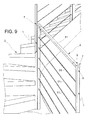
- figure 9 illustrates a portion of protective banister 2 of a flight of stairs 3 comprising a plurality of posts 1 according to the invention, fixed to the floor, on steps or intermediate landings.
- the post 1 comprises a tubular body 4.
- the tubular body 4 in the embodiment represented, has a hollow rectangular cross section, but it could have a cross section of any other shape suitable for the application.
- the tubular body 4 can be made for example from stainless steel, or from another material suitable for the specific application.
- the tubular body 4 comprises a lower end 5.
- the lower end 5 is suitable for being fixed to a floor, a step of a staircase 3 or another similar surface.
- the tubular body 4 also comprises an upper end 6.
- the post 1 also comprises a rotary joint 7.
- the rotary joint 7 is associated with the upper end 6 of the tubular body 4.
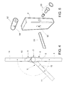
- the rotary joint 7 in greater detail, comprises a first member 8.
- the first member 8 can be connected to the upper end 6 of the tubular body 4.
- the rotary joint 7 also comprises a second member 9.
- the second member 9 can be connected to the free end 10 of a handrail 11, for example the handrail 11 of a banister 2.
- the first member 8 comprises a respective first articulation portion 12.
- the second member 9 comprises a respective second articulation portion 13.
- the first articulation portion 12 and the second articulation portion 13 are coupled together at a rotation axis A.
- the first member 8 comprises a first lateral recess 14.
- the first lateral recess 14 defines a respective first back surface 14a that coincides with the side surface of the first articulation portion 12.
- the second member 9 comprises a second lateral recess 15.
- the second lateral recess 15 defines a respective second back surface 15a that coincides with the side surface of the second articulation portion 13.
- the first articulation portion 12 of the first member 8 is engaged in the second lateral recess 15 of the second member 9; in the same way, the second articulation portion 13 of the second member 9 is engaged in the first lateral recess 14 of the first member 8.
- first back surface 14a and the second back surface 15a abut against one another.
- the rotary joint 7 has a minimal transversal bulk.
- the articulation portions 12,13 - and consequently the lateral recesses 14,15 - are sized so that the rotary joint 7 in assembly configuration has a transversal bulk not greater than that of the single components of the banister 2, i.e. the post 1 and the handrail 11.
- the first member 8 comprises a respective first tang 16.
- the first tang 16 can be inserted in the cavity of the upper end 6 of the tubular body 4.
- the second member 9 comprises a respective second tang 17.
- the second tang 17 can be inserted in the cavity of the free end 10 of the handrail 11.
- connection between the two components is very advantageous for example in installation situations in which the available space is limited, or in which it is intended to make a banister 2 that is particularly light but equally safe.
- the first articulation portion 12 is substantially cylindrical or semi-cylindrical in shape, with axis of symmetry coinciding with the rotation axis A.
- the second articulation portion 13 is also substantially cylindrical or semi-cylindrical in shape, with axis of symmetry coinciding with the rotation axis A.
- the first articulation portion 12 comprises a respective first hole 18 for the insertion of articulation means 19.
- the second articulation portion 13 comprises a respective second hole 20 for the insertion of the aforementioned articulation means 19.
- the articulation means 19 are for example of the screw type or another equivalent type.
- Lateral closing covers 21 are foreseen that hide the articulation means 19 from view.
- the first lateral recess 14 is defined in particular by a first surface 22 that is inclined with respect to the longitudinal axis of the tubular body 4.
- the second lateral recess 15 is defined by a second surface 23 that is inclined with respect to the longitudinal axis of the handrail 11.
- the first inclined surface 22 defines, with the side surface of the first member 8, a first abutment edge 24 on the second articulation portion 13, so as to make at least one end stop position in the rotation of the first member 8 with respect to the second member 9.
- the second inclined surface 23 defines, with the side surface of the second member 9, a second abutment edge 25 on the first articulation portion 12, again in order to obtain at least one end stop position.
- two opposite end stop positions are defined: in the first end stop position - in which the handrail 11 is represented with a broken line - the handrail 11 is inclined, for example, by 45° with respect to the post 1, whereas in the second end stop position the handrail 11 and the post 1 are aligned, i.e. an angle of 180° is defined between them.
- the angular values quoted above are quoted only as examples, and they are not, of course, limiting.
- the post 1 can be easily and effectively used both as lower post and as upper post of the same banister 2, situations in which the handrail 11 defines an angle with respect to the post 1 that is respectively obtuse and acute.
- this solution makes it possible to obtain inclinations between the post 1 and the handrail 11 that cannot be obtained with other known solutions in which the post is associated in an adjustable manner with an intermediate portion of the handrail.
- the first tang 16 can be blocked in the cavity of the upper end 6 of the tubular body 4 through a first screw 26 engaged in a first through hole 27 made in the tubular body 4.
- the first tang 16 comprises a respective first side seat 28 in which a first insert 29 is slidably housed, engaged by a first threaded hole 30.
- the second tang 17 can be blocked in the cavity of the free end 10 of the handrail 11 through a second screw 31 engaged in a second through hole 32 made in the handrail 11.
- the second tang 17 comprises a respective second side seat 33 in which a second insert 34 is slidably housed, engaged by a second threaded hole 35.
- the first member 8 and the second member 9 can be produced with a single machining process: indeed, no other machining is necessary, for example, to make the fixing holes of the first screw 26 or of the second screw 31.
- the first member 8 and the second member 9 can be made from sintered stainless steel.
- first member 8 and the second member 9 can be made from another material and/or with another technology, for example by moulding or fusion of a metallic alloy or of polymeric material.
- the first member 8 and the second member 9 of the rotary joint 7 are identical to each other and interchangeable.
- each of them can be associated without distinction with the tubular body 4 of the post 1 or with the handrail 11.
- the lower end 5 of the tubular body 4 comprises means 36 for adjusting the fixing height to a floor, a step of a staircase 3 or another similar surface.
- the adjustment means 36 make it possible to constrain the tubular body 4 of the post at different heights with respect to the fixing surface.
- the adjustment means 36 comprise a support 37.
- the support 37 is fixed inside the cavity of the lower end 5 of the tubular body 4.
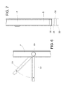
- the support 37 has one or more plates 38 connected to it, that can be superimposed, resting on the floor, on a step of a staircase 3 or on another similar surface. As made clear for example in the detail of figure 7 , by mounting a suitable number of plates 38 superimposed on top of one another, it is possible to vary the mounting height of the post 1.
- the plates 38 can be made with various thicknesses, to more or less precisely adjust the mounting height of the post 1.
- the support 37 comprises a head 39 able to be fixed inside the cavity of the lower end 5 of the tubular body 4 through upper screws 40.
- the head 40 has lateral appendages 41 in which respective threaded holes 42 are foreseen.
- the upper screws 40 pass through respective countersunk holes 43 foreseen in the tubular body 4, and are screwed in the aforementioned threaded holes 42.
- the upper screws 40 can then be hidden from view with respective covers 44.
- the support 37 also comprises a threaded pin 45 screwed into a corresponding mother screw foreseen in the head 39.
- the threaded pin 45 has a length such as to partially protrude from the opening of the lower end 5 of the tubular body 4.
- the support 37 also comprises a block 46.
- the block 46 is associated with the intermediate portion of the threaded pin 45; in particular, the block 46 has a threaded through hole into which the threaded pin 45 is completely screwed.
- the block 46 comprises a lower portion 47 to which the plates 38 can be connected.
- the plates 38 can be connected to the lower portion 47 through lower screws 48.
- Each plate 38 as shown in figure 8 , has a respective central hole 49 for the threaded pin 45 to pass through.
- the lower end of the threaded pin 45 can in turn be fixed to the floor, to a step of a staircase 3 or to another similar surface through a self-threading screw, a nut, or other similar elements.
- the tubular body 4 of the post 1 comprises one or more slots 50 for the adjustable connection of respective wires 51 of the banister 2, or of a different protective structure.
- the post 1 comprises one or more bushings 52 rotatably supported inside the cavity of the tubular body 4 at the slots 50, through screw means 53.
- the bushings 52 have respective side holes 54 for the insertion of the terminal ends of the respective wires 51.
- this solution makes it possible to easily adjust the inclination of each wire 51 with respect to the post 1 in an independent manner, adapting precisely to the inclination of the flight of stairs 3.
- the proposed solution firstly makes it possible, as has been seen, to obtain an adjustable inclination between the post and the handrail having an angular excursion that cannot be obtained with other known applications. Consequently, thanks to such a wide angular excursion, the post according to the invention can be used both as a lower post and as an upper post of the same banister.
- the solution devised is also particularly simple, slim and of limited bulk: it is thus particularly recommended in situations of little available space and/or in which it is intended to make a particularly light banister.
- the solution of adjusting the installation height of the post is also of particular interest, also allowing possible unevenness between different areas of the flight of stairs in which the single posts are mounted to be compensated.
Landscapes
- Engineering & Computer Science (AREA)
- Architecture (AREA)
- Civil Engineering (AREA)
- Structural Engineering (AREA)
- Steps, Ramps, And Handrails (AREA)
- Cleaning In Electrography (AREA)
- Artificial Fish Reefs (AREA)
- Building Awnings And Sunshades (AREA)
Priority Applications (1)
| Application Number | Priority Date | Filing Date | Title |
|---|---|---|---|
| HRP20171066TT HRP20171066T1 (hr) | 2014-01-31 | 2017-07-12 | Stup za balustre, ograde i slično |
Applications Claiming Priority (1)
| Application Number | Priority Date | Filing Date | Title |
|---|---|---|---|
| ITBO20140042 | 2014-01-31 |
Publications (3)
| Publication Number | Publication Date |
|---|---|
| EP2902566A2 true EP2902566A2 (fr) | 2015-08-05 |
| EP2902566A3 EP2902566A3 (fr) | 2015-11-25 |
| EP2902566B1 EP2902566B1 (fr) | 2017-04-12 |
Family
ID=50391253
Family Applications (1)
| Application Number | Title | Priority Date | Filing Date |
|---|---|---|---|
| EP15153120.9A Active EP2902566B1 (fr) | 2014-01-31 | 2015-01-29 | Montants de balustrades, rampes et similaires |
Country Status (3)
| Country | Link |
|---|---|
| EP (1) | EP2902566B1 (fr) |
| ES (1) | ES2635634T3 (fr) |
| HR (1) | HRP20171066T1 (fr) |
Cited By (3)
| Publication number | Priority date | Publication date | Assignee | Title |
|---|---|---|---|---|
| US11136764B2 (en) * | 2018-05-04 | 2021-10-05 | Vinylast, Inc. | Bracket with horizontal and vertical swivel capabilities |
| US11174645B2 (en) * | 2019-07-02 | 2021-11-16 | The Landmark Group, Inc. | Elbow joint connector |
| US20250034879A1 (en) * | 2023-07-25 | 2025-01-30 | Daniel Schlatter | Handrail connection system |
Family Cites Families (4)
| Publication number | Priority date | Publication date | Assignee | Title |
|---|---|---|---|---|
| JP3940578B2 (ja) * | 2001-10-18 | 2007-07-04 | 周平 泉 | 手摺連結具 |
| DE20307065U1 (de) * | 2003-05-07 | 2003-08-28 | A. Steiner Edelstahl Be- und Verarbeitungs GmbH, 27367 Sottrum | Verstellbarer Montagefuß aus Edelstahl |
| JP4044884B2 (ja) * | 2003-09-05 | 2008-02-06 | 東洋エクステリア株式会社 | ビーム連結構造及びこれを用いたビーム手摺 |
| US7540472B2 (en) * | 2007-05-10 | 2009-06-02 | Suncor Stainless, Inc. | Rail and ramp systems with adjustable fittings |
-
2015
- 2015-01-29 EP EP15153120.9A patent/EP2902566B1/fr active Active
- 2015-01-29 ES ES15153120.9T patent/ES2635634T3/es active Active
-
2017
- 2017-07-12 HR HRP20171066TT patent/HRP20171066T1/hr unknown
Non-Patent Citations (1)
| Title |
|---|
| None |
Cited By (4)
| Publication number | Priority date | Publication date | Assignee | Title |
|---|---|---|---|---|
| US11136764B2 (en) * | 2018-05-04 | 2021-10-05 | Vinylast, Inc. | Bracket with horizontal and vertical swivel capabilities |
| US11174645B2 (en) * | 2019-07-02 | 2021-11-16 | The Landmark Group, Inc. | Elbow joint connector |
| US11585098B2 (en) | 2019-07-02 | 2023-02-21 | The Landmark Group, Inc. | Elbow joint connector |
| US20250034879A1 (en) * | 2023-07-25 | 2025-01-30 | Daniel Schlatter | Handrail connection system |
Also Published As
| Publication number | Publication date |
|---|---|
| EP2902566A3 (fr) | 2015-11-25 |
| ES2635634T3 (es) | 2017-10-04 |
| EP2902566B1 (fr) | 2017-04-12 |
| HRP20171066T1 (hr) | 2017-10-06 |
Similar Documents
| Publication | Publication Date | Title |
|---|---|---|
| US20080191185A1 (en) | Handrail assemblies | |
| US8936233B1 (en) | Baluster bracket assembly | |
| US20090179183A1 (en) | Slot Rail Assembly | |
| US11692383B2 (en) | Hinge assembly for elevational rails | |
| US7044450B2 (en) | Quick rail system with adjustable support | |
| US20070246698A1 (en) | Baluster ball joint adapter attachment for a baluster to stair rail(s) and base | |
| EP2902566B1 (fr) | Montants de balustrades, rampes et similaires | |
| KR101854330B1 (ko) | 난간고정용 브라켓 | |
| US20150211235A1 (en) | Baluster Bracket Assembly | |
| US6736373B2 (en) | Connector assembly for handrail installation | |
| US6860472B2 (en) | Quick rail system | |
| US10947738B2 (en) | Adjustable balustrade system | |
| US20030234391A1 (en) | Aluminum universal angle brackets | |
| CA2687925C (fr) | Balustre extensible | |
| EP2746486A2 (fr) | Montant pour rampes, balustrades, et similaires | |
| EP1335081A2 (fr) | Ensembles de main courante | |
| KR101978360B1 (ko) | 개량형 난간의 결합구조 | |
| KR101099637B1 (ko) | 핸드레일 서포트어셈블리 | |
| US20120012802A1 (en) | Rail Assembly Having a Baluster Swing Bracket | |
| US12247401B2 (en) | Baluster installation system and method | |
| EP3822425A1 (fr) | Joint articulé pour balustrades, railings et similaires | |
| EP3767051A1 (fr) | Montant pour balustrades, garde-corps et similaires | |
| US12326000B2 (en) | Handrail attachment system and method | |
| KR102254953B1 (ko) | 계단 난간용 지주의 각도조절구조체 | |
| JP6914536B2 (ja) | 横桟材用仮固定具 |
Legal Events
| Date | Code | Title | Description |
|---|---|---|---|
| PUAI | Public reference made under article 153(3) epc to a published international application that has entered the european phase |
Free format text: ORIGINAL CODE: 0009012 |
|
| 17P | Request for examination filed |
Effective date: 20150129 |
|
| AK | Designated contracting states |
Kind code of ref document: A2 Designated state(s): AL AT BE BG CH CY CZ DE DK EE ES FI FR GB GR HR HU IE IS IT LI LT LU LV MC MK MT NL NO PL PT RO RS SE SI SK SM TR |
|
| AX | Request for extension of the european patent |
Extension state: BA ME |
|
| PUAL | Search report despatched |
Free format text: ORIGINAL CODE: 0009013 |
|
| AK | Designated contracting states |
Kind code of ref document: A3 Designated state(s): AL AT BE BG CH CY CZ DE DK EE ES FI FR GB GR HR HU IE IS IT LI LT LU LV MC MK MT NL NO PL PT RO RS SE SI SK SM TR |
|
| AX | Request for extension of the european patent |
Extension state: BA ME |
|
| RIC1 | Information provided on ipc code assigned before grant |
Ipc: E04F 11/18 20060101AFI20151022BHEP |
|
| 17P | Request for examination filed |
Effective date: 20160511 |
|
| RBV | Designated contracting states (corrected) |
Designated state(s): AL AT BE BG CH CY CZ DE DK EE ES FI FR GB GR HR HU IE IS IT LI LT LU LV MC MK MT NL NO PL PT RO RS SE SI SK SM TR |
|
| GRAP | Despatch of communication of intention to grant a patent |
Free format text: ORIGINAL CODE: EPIDOSNIGR1 |
|
| INTG | Intention to grant announced |
Effective date: 20161103 |
|
| GRAS | Grant fee paid |
Free format text: ORIGINAL CODE: EPIDOSNIGR3 |
|
| GRAA | (expected) grant |
Free format text: ORIGINAL CODE: 0009210 |
|
| AK | Designated contracting states |
Kind code of ref document: B1 Designated state(s): AL AT BE BG CH CY CZ DE DK EE ES FI FR GB GR HR HU IE IS IT LI LT LU LV MC MK MT NL NO PL PT RO RS SE SI SK SM TR |
|
| REG | Reference to a national code |
Ref country code: GB Ref legal event code: FG4D |
|
| REG | Reference to a national code |
Ref country code: CH Ref legal event code: EP |
|
| REG | Reference to a national code |
Ref country code: IE Ref legal event code: FG4D |
|
| REG | Reference to a national code |
Ref country code: AT Ref legal event code: REF Ref document number: 884035 Country of ref document: AT Kind code of ref document: T Effective date: 20170515 |
|
| REG | Reference to a national code |
Ref country code: DE Ref legal event code: R096 Ref document number: 602015002157 Country of ref document: DE |
|
| REG | Reference to a national code |
Ref country code: HR Ref legal event code: TUEP Ref document number: P20171066 Country of ref document: HR |
|
| REG | Reference to a national code |
Ref country code: NL Ref legal event code: FP |
|
| REG | Reference to a national code |
Ref country code: LT Ref legal event code: MG4D |
|
| REG | Reference to a national code |
Ref country code: AT Ref legal event code: MK05 Ref document number: 884035 Country of ref document: AT Kind code of ref document: T Effective date: 20170412 |
|
| REG | Reference to a national code |
Ref country code: ES Ref legal event code: FG2A Ref document number: 2635634 Country of ref document: ES Kind code of ref document: T3 Effective date: 20171004 |
|
| REG | Reference to a national code |
Ref country code: HR Ref legal event code: T1PR Ref document number: P20171066 Country of ref document: HR |
|
| PG25 | Lapsed in a contracting state [announced via postgrant information from national office to epo] |
Ref country code: AT Free format text: LAPSE BECAUSE OF FAILURE TO SUBMIT A TRANSLATION OF THE DESCRIPTION OR TO PAY THE FEE WITHIN THE PRESCRIBED TIME-LIMIT Effective date: 20170412 Ref country code: GR Free format text: LAPSE BECAUSE OF FAILURE TO SUBMIT A TRANSLATION OF THE DESCRIPTION OR TO PAY THE FEE WITHIN THE PRESCRIBED TIME-LIMIT Effective date: 20170713 Ref country code: NO Free format text: LAPSE BECAUSE OF FAILURE TO SUBMIT A TRANSLATION OF THE DESCRIPTION OR TO PAY THE FEE WITHIN THE PRESCRIBED TIME-LIMIT Effective date: 20170712 Ref country code: FI Free format text: LAPSE BECAUSE OF FAILURE TO SUBMIT A TRANSLATION OF THE DESCRIPTION OR TO PAY THE FEE WITHIN THE PRESCRIBED TIME-LIMIT Effective date: 20170412 Ref country code: LT Free format text: LAPSE BECAUSE OF FAILURE TO SUBMIT A TRANSLATION OF THE DESCRIPTION OR TO PAY THE FEE WITHIN THE PRESCRIBED TIME-LIMIT Effective date: 20170412 |
|
| PG25 | Lapsed in a contracting state [announced via postgrant information from national office to epo] |
Ref country code: IS Free format text: LAPSE BECAUSE OF FAILURE TO SUBMIT A TRANSLATION OF THE DESCRIPTION OR TO PAY THE FEE WITHIN THE PRESCRIBED TIME-LIMIT Effective date: 20170812 Ref country code: BG Free format text: LAPSE BECAUSE OF FAILURE TO SUBMIT A TRANSLATION OF THE DESCRIPTION OR TO PAY THE FEE WITHIN THE PRESCRIBED TIME-LIMIT Effective date: 20170712 Ref country code: PL Free format text: LAPSE BECAUSE OF FAILURE TO SUBMIT A TRANSLATION OF THE DESCRIPTION OR TO PAY THE FEE WITHIN THE PRESCRIBED TIME-LIMIT Effective date: 20170412 Ref country code: SE Free format text: LAPSE BECAUSE OF FAILURE TO SUBMIT A TRANSLATION OF THE DESCRIPTION OR TO PAY THE FEE WITHIN THE PRESCRIBED TIME-LIMIT Effective date: 20170412 Ref country code: LV Free format text: LAPSE BECAUSE OF FAILURE TO SUBMIT A TRANSLATION OF THE DESCRIPTION OR TO PAY THE FEE WITHIN THE PRESCRIBED TIME-LIMIT Effective date: 20170412 Ref country code: RS Free format text: LAPSE BECAUSE OF FAILURE TO SUBMIT A TRANSLATION OF THE DESCRIPTION OR TO PAY THE FEE WITHIN THE PRESCRIBED TIME-LIMIT Effective date: 20170412 |
|
| REG | Reference to a national code |
Ref country code: DE Ref legal event code: R097 Ref document number: 602015002157 Country of ref document: DE |
|
| REG | Reference to a national code |
Ref country code: FR Ref legal event code: PLFP Year of fee payment: 4 |
|
| PG25 | Lapsed in a contracting state [announced via postgrant information from national office to epo] |
Ref country code: DK Free format text: LAPSE BECAUSE OF FAILURE TO SUBMIT A TRANSLATION OF THE DESCRIPTION OR TO PAY THE FEE WITHIN THE PRESCRIBED TIME-LIMIT Effective date: 20170412 Ref country code: EE Free format text: LAPSE BECAUSE OF FAILURE TO SUBMIT A TRANSLATION OF THE DESCRIPTION OR TO PAY THE FEE WITHIN THE PRESCRIBED TIME-LIMIT Effective date: 20170412 Ref country code: RO Free format text: LAPSE BECAUSE OF FAILURE TO SUBMIT A TRANSLATION OF THE DESCRIPTION OR TO PAY THE FEE WITHIN THE PRESCRIBED TIME-LIMIT Effective date: 20170412 Ref country code: SK Free format text: LAPSE BECAUSE OF FAILURE TO SUBMIT A TRANSLATION OF THE DESCRIPTION OR TO PAY THE FEE WITHIN THE PRESCRIBED TIME-LIMIT Effective date: 20170412 Ref country code: CZ Free format text: LAPSE BECAUSE OF FAILURE TO SUBMIT A TRANSLATION OF THE DESCRIPTION OR TO PAY THE FEE WITHIN THE PRESCRIBED TIME-LIMIT Effective date: 20170412 |
|
| PLBE | No opposition filed within time limit |
Free format text: ORIGINAL CODE: 0009261 |
|
| STAA | Information on the status of an ep patent application or granted ep patent |
Free format text: STATUS: NO OPPOSITION FILED WITHIN TIME LIMIT |
|
| PG25 | Lapsed in a contracting state [announced via postgrant information from national office to epo] |
Ref country code: SM Free format text: LAPSE BECAUSE OF FAILURE TO SUBMIT A TRANSLATION OF THE DESCRIPTION OR TO PAY THE FEE WITHIN THE PRESCRIBED TIME-LIMIT Effective date: 20170412 |
|
| 26N | No opposition filed |
Effective date: 20180115 |
|
| PG25 | Lapsed in a contracting state [announced via postgrant information from national office to epo] |
Ref country code: SI Free format text: LAPSE BECAUSE OF FAILURE TO SUBMIT A TRANSLATION OF THE DESCRIPTION OR TO PAY THE FEE WITHIN THE PRESCRIBED TIME-LIMIT Effective date: 20170412 |
|
| REG | Reference to a national code |
Ref country code: CH Ref legal event code: PL |
|
| PG25 | Lapsed in a contracting state [announced via postgrant information from national office to epo] |
Ref country code: LU Free format text: LAPSE BECAUSE OF NON-PAYMENT OF DUE FEES Effective date: 20180129 |
|
| PG25 | Lapsed in a contracting state [announced via postgrant information from national office to epo] |
Ref country code: LI Free format text: LAPSE BECAUSE OF NON-PAYMENT OF DUE FEES Effective date: 20180131 Ref country code: CH Free format text: LAPSE BECAUSE OF NON-PAYMENT OF DUE FEES Effective date: 20180131 |
|
| REG | Reference to a national code |
Ref country code: HR Ref legal event code: ODRP Ref document number: P20171066 Country of ref document: HR Payment date: 20190118 Year of fee payment: 5 |
|
| PG25 | Lapsed in a contracting state [announced via postgrant information from national office to epo] |
Ref country code: MC Free format text: LAPSE BECAUSE OF FAILURE TO SUBMIT A TRANSLATION OF THE DESCRIPTION OR TO PAY THE FEE WITHIN THE PRESCRIBED TIME-LIMIT Effective date: 20170412 |
|
| GBPC | Gb: european patent ceased through non-payment of renewal fee |
Effective date: 20190129 |
|
| PG25 | Lapsed in a contracting state [announced via postgrant information from national office to epo] |
Ref country code: GB Free format text: LAPSE BECAUSE OF NON-PAYMENT OF DUE FEES Effective date: 20190129 |
|
| REG | Reference to a national code |
Ref country code: HR Ref legal event code: ODRP Ref document number: P20171066 Country of ref document: HR Payment date: 20200121 Year of fee payment: 6 |
|
| PG25 | Lapsed in a contracting state [announced via postgrant information from national office to epo] |
Ref country code: TR Free format text: LAPSE BECAUSE OF FAILURE TO SUBMIT A TRANSLATION OF THE DESCRIPTION OR TO PAY THE FEE WITHIN THE PRESCRIBED TIME-LIMIT Effective date: 20170412 |
|
| PG25 | Lapsed in a contracting state [announced via postgrant information from national office to epo] |
Ref country code: PT Free format text: LAPSE BECAUSE OF FAILURE TO SUBMIT A TRANSLATION OF THE DESCRIPTION OR TO PAY THE FEE WITHIN THE PRESCRIBED TIME-LIMIT Effective date: 20170412 |
|
| PG25 | Lapsed in a contracting state [announced via postgrant information from national office to epo] |
Ref country code: CY Free format text: LAPSE BECAUSE OF FAILURE TO SUBMIT A TRANSLATION OF THE DESCRIPTION OR TO PAY THE FEE WITHIN THE PRESCRIBED TIME-LIMIT Effective date: 20170412 Ref country code: HU Free format text: LAPSE BECAUSE OF FAILURE TO SUBMIT A TRANSLATION OF THE DESCRIPTION OR TO PAY THE FEE WITHIN THE PRESCRIBED TIME-LIMIT; INVALID AB INITIO Effective date: 20150129 |
|
| PG25 | Lapsed in a contracting state [announced via postgrant information from national office to epo] |
Ref country code: AL Free format text: LAPSE BECAUSE OF FAILURE TO SUBMIT A TRANSLATION OF THE DESCRIPTION OR TO PAY THE FEE WITHIN THE PRESCRIBED TIME-LIMIT Effective date: 20170412 |
|
| PGFP | Annual fee paid to national office [announced via postgrant information from national office to epo] |
Ref country code: MT Payment date: 20201231 Year of fee payment: 7 |
|
| REG | Reference to a national code |
Ref country code: HR Ref legal event code: ODRP Ref document number: P20171066 Country of ref document: HR Payment date: 20210105 Year of fee payment: 7 |
|
| PGFP | Annual fee paid to national office [announced via postgrant information from national office to epo] |
Ref country code: NL Payment date: 20210126 Year of fee payment: 7 Ref country code: IE Payment date: 20210127 Year of fee payment: 7 Ref country code: IT Payment date: 20210104 Year of fee payment: 7 Ref country code: FR Payment date: 20210125 Year of fee payment: 7 |
|
| PGFP | Annual fee paid to national office [announced via postgrant information from national office to epo] |
Ref country code: ES Payment date: 20210201 Year of fee payment: 7 Ref country code: BE Payment date: 20210127 Year of fee payment: 7 Ref country code: DE Payment date: 20210127 Year of fee payment: 7 |
|
| PGFP | Annual fee paid to national office [announced via postgrant information from national office to epo] |
Ref country code: HR Payment date: 20210105 Year of fee payment: 7 |
|
| PGFP | Annual fee paid to national office [announced via postgrant information from national office to epo] |
Ref country code: MK Payment date: 20210105 Year of fee payment: 7 |
|
| REG | Reference to a national code |
Ref country code: DE Ref legal event code: R119 Ref document number: 602015002157 Country of ref document: DE |
|
| REG | Reference to a national code |
Ref country code: HR Ref legal event code: PBON Ref document number: P20171066 Country of ref document: HR Effective date: 20220129 |
|
| REG | Reference to a national code |
Ref country code: NL Ref legal event code: MM Effective date: 20220201 |
|
| REG | Reference to a national code |
Ref country code: BE Ref legal event code: MM Effective date: 20220131 |
|
| PG25 | Lapsed in a contracting state [announced via postgrant information from national office to epo] |
Ref country code: NL Free format text: LAPSE BECAUSE OF NON-PAYMENT OF DUE FEES Effective date: 20220201 Ref country code: HR Free format text: LAPSE BECAUSE OF NON-PAYMENT OF DUE FEES Effective date: 20220129 Ref country code: DE Free format text: LAPSE BECAUSE OF NON-PAYMENT OF DUE FEES Effective date: 20220802 |
|
| PG25 | Lapsed in a contracting state [announced via postgrant information from national office to epo] |
Ref country code: FR Free format text: LAPSE BECAUSE OF NON-PAYMENT OF DUE FEES Effective date: 20220131 Ref country code: BE Free format text: LAPSE BECAUSE OF NON-PAYMENT OF DUE FEES Effective date: 20220131 |
|
| PG25 | Lapsed in a contracting state [announced via postgrant information from national office to epo] |
Ref country code: IT Free format text: LAPSE BECAUSE OF NON-PAYMENT OF DUE FEES Effective date: 20220129 Ref country code: IE Free format text: LAPSE BECAUSE OF NON-PAYMENT OF DUE FEES Effective date: 20220129 |
|
| REG | Reference to a national code |
Ref country code: ES Ref legal event code: FD2A Effective date: 20230331 |
|
| PG25 | Lapsed in a contracting state [announced via postgrant information from national office to epo] |
Ref country code: ES Free format text: LAPSE BECAUSE OF NON-PAYMENT OF DUE FEES Effective date: 20220130 |
|
| PG25 | Lapsed in a contracting state [announced via postgrant information from national office to epo] |
Ref country code: MT Free format text: LAPSE BECAUSE OF NON-PAYMENT OF DUE FEES Effective date: 20220129 |