EP2902697B1 - Dispositif d'éclairage formé de bande d'élement d'éclairage avec un couplage magnétique - Google Patents
Dispositif d'éclairage formé de bande d'élement d'éclairage avec un couplage magnétique Download PDFInfo
- Publication number
- EP2902697B1 EP2902697B1 EP15153610.9A EP15153610A EP2902697B1 EP 2902697 B1 EP2902697 B1 EP 2902697B1 EP 15153610 A EP15153610 A EP 15153610A EP 2902697 B1 EP2902697 B1 EP 2902697B1
- Authority
- EP
- European Patent Office
- Prior art keywords
- strip
- support foil
- coupling
- lighting elements
- lighting
- Prior art date
- Legal status (The legal status is an assumption and is not a legal conclusion. Google has not performed a legal analysis and makes no representation as to the accuracy of the status listed.)
- Not-in-force
Links
- 230000008878 coupling Effects 0.000 title claims description 88
- 238000010168 coupling process Methods 0.000 title claims description 88
- 238000005859 coupling reaction Methods 0.000 title claims description 88
- 230000005291 magnetic effect Effects 0.000 title claims description 25
- 239000011888 foil Substances 0.000 claims description 100
- 239000000696 magnetic material Substances 0.000 claims description 22
- 238000005452 bending Methods 0.000 claims description 20
- 239000003302 ferromagnetic material Substances 0.000 claims description 16
- 230000000452 restraining effect Effects 0.000 claims description 11
- 238000009434 installation Methods 0.000 claims description 10
- 238000000034 method Methods 0.000 claims description 9
- 229920001971 elastomer Polymers 0.000 claims description 6
- 230000036961 partial effect Effects 0.000 claims description 6
- 239000004020 conductor Substances 0.000 claims description 4
- 229910000859 α-Fe Inorganic materials 0.000 claims description 4
- 230000000670 limiting effect Effects 0.000 claims description 3
- 239000002184 metal Substances 0.000 description 66
- 229910052751 metal Inorganic materials 0.000 description 66
- 239000000463 material Substances 0.000 description 8
- XEEYBQQBJWHFJM-UHFFFAOYSA-N Iron Chemical compound [Fe] XEEYBQQBJWHFJM-UHFFFAOYSA-N 0.000 description 4
- 230000009471 action Effects 0.000 description 4
- 239000000853 adhesive Substances 0.000 description 3
- 230000001070 adhesive effect Effects 0.000 description 3
- PXHVJJICTQNCMI-UHFFFAOYSA-N Nickel Chemical compound [Ni] PXHVJJICTQNCMI-UHFFFAOYSA-N 0.000 description 2
- 239000011248 coating agent Substances 0.000 description 2
- 238000000576 coating method Methods 0.000 description 2
- 238000007906 compression Methods 0.000 description 2
- 230000006835 compression Effects 0.000 description 2
- 230000001419 dependent effect Effects 0.000 description 2
- 230000000694 effects Effects 0.000 description 2
- 239000012777 electrically insulating material Substances 0.000 description 2
- 229910052742 iron Inorganic materials 0.000 description 2
- 239000006249 magnetic particle Substances 0.000 description 2
- 239000000758 substrate Substances 0.000 description 2
- 229920001621 AMOLED Polymers 0.000 description 1
- 229920000459 Nitrile rubber Polymers 0.000 description 1
- 229910000639 Spring steel Inorganic materials 0.000 description 1
- 229910000831 Steel Inorganic materials 0.000 description 1
- 239000004809 Teflon Substances 0.000 description 1
- 229920006362 Teflon® Polymers 0.000 description 1
- 238000004026 adhesive bonding Methods 0.000 description 1
- 230000002411 adverse Effects 0.000 description 1
- 230000004075 alteration Effects 0.000 description 1
- 239000011230 binding agent Substances 0.000 description 1
- 230000005540 biological transmission Effects 0.000 description 1
- 230000015572 biosynthetic process Effects 0.000 description 1
- 239000003990 capacitor Substances 0.000 description 1
- 239000012876 carrier material Substances 0.000 description 1
- 239000000919 ceramic Substances 0.000 description 1
- 229920006235 chlorinated polyethylene elastomer Polymers 0.000 description 1
- 229910017052 cobalt Inorganic materials 0.000 description 1
- 239000010941 cobalt Substances 0.000 description 1
- GUTLYIVDDKVIGB-UHFFFAOYSA-N cobalt atom Chemical compound [Co] GUTLYIVDDKVIGB-UHFFFAOYSA-N 0.000 description 1
- 238000001816 cooling Methods 0.000 description 1
- 238000013461 design Methods 0.000 description 1
- 239000013536 elastomeric material Substances 0.000 description 1
- 238000005401 electroluminescence Methods 0.000 description 1
- 238000005516 engineering process Methods 0.000 description 1
- 238000009472 formulation Methods 0.000 description 1
- 230000005484 gravity Effects 0.000 description 1
- 229910052736 halogen Inorganic materials 0.000 description 1
- 150000002367 halogens Chemical class 0.000 description 1
- 238000010438 heat treatment Methods 0.000 description 1
- 229920006168 hydrated nitrile rubber Polymers 0.000 description 1
- 239000011810 insulating material Substances 0.000 description 1
- 230000003993 interaction Effects 0.000 description 1
- 239000004816 latex Substances 0.000 description 1
- 229920000126 latex Polymers 0.000 description 1
- 238000012423 maintenance Methods 0.000 description 1
- 230000007246 mechanism Effects 0.000 description 1
- 239000000203 mixture Substances 0.000 description 1
- 238000012986 modification Methods 0.000 description 1
- 230000004048 modification Effects 0.000 description 1
- 229910052759 nickel Inorganic materials 0.000 description 1
- 230000003287 optical effect Effects 0.000 description 1
- 238000013021 overheating Methods 0.000 description 1
- 230000002085 persistent effect Effects 0.000 description 1
- 229920003223 poly(pyromellitimide-1,4-diphenyl ether) Polymers 0.000 description 1
- 229920001296 polysiloxane Polymers 0.000 description 1
- 238000002360 preparation method Methods 0.000 description 1
- 230000001681 protective effect Effects 0.000 description 1
- 230000009467 reduction Effects 0.000 description 1
- 229910001220 stainless steel Inorganic materials 0.000 description 1
- 239000010935 stainless steel Substances 0.000 description 1
- 230000003068 static effect Effects 0.000 description 1
- 239000010959 steel Substances 0.000 description 1
- 238000006467 substitution reaction Methods 0.000 description 1
- 229920002725 thermoplastic elastomer Polymers 0.000 description 1
Images



Classifications
-
- F—MECHANICAL ENGINEERING; LIGHTING; HEATING; WEAPONS; BLASTING
- F21—LIGHTING
- F21V—FUNCTIONAL FEATURES OR DETAILS OF LIGHTING DEVICES OR SYSTEMS THEREOF; STRUCTURAL COMBINATIONS OF LIGHTING DEVICES WITH OTHER ARTICLES, NOT OTHERWISE PROVIDED FOR
- F21V19/00—Fastening of light sources or lamp holders
- F21V19/001—Fastening of light sources or lamp holders the light sources being semiconductors devices, e.g. LEDs
- F21V19/003—Fastening of light source holders, e.g. of circuit boards or substrates holding light sources
-
- F—MECHANICAL ENGINEERING; LIGHTING; HEATING; WEAPONS; BLASTING
- F21—LIGHTING
- F21S—NON-PORTABLE LIGHTING DEVICES; SYSTEMS THEREOF; VEHICLE LIGHTING DEVICES SPECIALLY ADAPTED FOR VEHICLE EXTERIORS
- F21S4/00—Lighting devices or systems using a string or strip of light sources
- F21S4/20—Lighting devices or systems using a string or strip of light sources with light sources held by or within elongate supports
- F21S4/22—Lighting devices or systems using a string or strip of light sources with light sources held by or within elongate supports flexible or deformable, e.g. into a curved shape
- F21S4/24—Lighting devices or systems using a string or strip of light sources with light sources held by or within elongate supports flexible or deformable, e.g. into a curved shape of ribbon or tape form, e.g. LED tapes
-
- F—MECHANICAL ENGINEERING; LIGHTING; HEATING; WEAPONS; BLASTING
- F21—LIGHTING
- F21V—FUNCTIONAL FEATURES OR DETAILS OF LIGHTING DEVICES OR SYSTEMS THEREOF; STRUCTURAL COMBINATIONS OF LIGHTING DEVICES WITH OTHER ARTICLES, NOT OTHERWISE PROVIDED FOR
- F21V17/00—Fastening of component parts of lighting devices, e.g. shades, globes, refractors, reflectors, filters, screens, grids or protective cages
- F21V17/10—Fastening of component parts of lighting devices, e.g. shades, globes, refractors, reflectors, filters, screens, grids or protective cages characterised by specific fastening means or way of fastening
- F21V17/105—Fastening of component parts of lighting devices, e.g. shades, globes, refractors, reflectors, filters, screens, grids or protective cages characterised by specific fastening means or way of fastening using magnets
-
- F—MECHANICAL ENGINEERING; LIGHTING; HEATING; WEAPONS; BLASTING
- F21—LIGHTING
- F21V—FUNCTIONAL FEATURES OR DETAILS OF LIGHTING DEVICES OR SYSTEMS THEREOF; STRUCTURAL COMBINATIONS OF LIGHTING DEVICES WITH OTHER ARTICLES, NOT OTHERWISE PROVIDED FOR
- F21V21/00—Supporting, suspending, or attaching arrangements for lighting devices; Hand grips
- F21V21/005—Supporting, suspending, or attaching arrangements for lighting devices; Hand grips for several lighting devices in an end-to-end arrangement, i.e. light tracks
-
- F—MECHANICAL ENGINEERING; LIGHTING; HEATING; WEAPONS; BLASTING
- F21—LIGHTING
- F21Y—INDEXING SCHEME ASSOCIATED WITH SUBCLASSES F21K, F21L, F21S and F21V, RELATING TO THE FORM OR THE KIND OF THE LIGHT SOURCES OR OF THE COLOUR OF THE LIGHT EMITTED
- F21Y2103/00—Elongate light sources, e.g. fluorescent tubes
- F21Y2103/10—Elongate light sources, e.g. fluorescent tubes comprising a linear array of point-like light-generating elements
-
- F—MECHANICAL ENGINEERING; LIGHTING; HEATING; WEAPONS; BLASTING
- F21—LIGHTING
- F21Y—INDEXING SCHEME ASSOCIATED WITH SUBCLASSES F21K, F21L, F21S and F21V, RELATING TO THE FORM OR THE KIND OF THE LIGHT SOURCES OR OF THE COLOUR OF THE LIGHT EMITTED
- F21Y2115/00—Light-generating elements of semiconductor light sources
- F21Y2115/10—Light-emitting diodes [LED]
Definitions
- the present disclosure relates to the lighting technology field. More specifically, this disclosure relates to lighting apparatuses based on strips of lighting elements.
- Lighting apparatuses are commonly used to provide artificial lighting to objects in the broadest meaning of the term (for example, indoor environments). Particularly, lighting apparatuses based on strips of lighting elements (for example, LEDs) are becoming increasingly popular, in replacement of the lighting apparatuses based on conventional lighting sources (such as halogen or fluorescent lamps).
- a LED Light Emitting Diode
- PN junction diode which is capable of emitting light when forward biased (thanks to the emission of energy of the electrons coming from its N region that recombine with the holes of its P region); the LEDs have long life, high efficiency, and they are very safe (since they operate at extremely low voltages).
- a LED strip comprises a strip of flexible printed circuit, on which a battery of LED is mounted. The LED strips are very versatile, thereby allowing achieving creative and appealing aesthetic effects.
- Each LED strip is normally applied on a support element. This allows forcing the LED strip to take well defined shapes, and to maintain them in a stable manner. Moreover, the support element may also be used to dissipate the heat that is produced by the LED strip in operation.
- the application of the LED strip on the support element is facilitated by the typical presence of a layer of adhesive material on its rear surface (opposite a front surface where the LEDs are mounted); for this purpose, it is sufficient to remove a strip of protective paper covering the layer of adhesive material, to position the LED strip onto the support element and to make it adhere thereto with a slight pressure.
- Italian patent application MI20 11A0001 64 also published as EP2484956 A1 , describes a flexible lighting element.
- This flexible lighting element comprises a strip of lighting sources based on LEDs, which is covered by an outer coating of silicone-based elastomeric material that may be cold extruded and vulcanized; the lighting strip is interposed between the outer coating and a support of thermally conductive material on which the strip rests.
- the coupling between the LED strip and the support element may be problematic in specific conditions.
- the support element may be flexible (for example, a metal foil) to allow modelling its shape, and then the one of the LED strip as well, as desired according to personal needs (for example, to obtain different decorative effects).
- the LED strip being integral therewith is subject to stresses that may damage it.
- the LED strip is arranged inside a curve of the support element, it is subject to a compression that may detach its flexible printed circuit from the support element; this creates a ridge in the flexible printed circuit that may cause a detachment of the LEDs mounted thereon.
- the LED strip is arranged outside a curve of the support element, it is subject to a traction that may tear its flexible printed circuit.
- the LED strip would not be integral with the support element any longer. Consequently, the LED strip might detach at various points from the support element with the formation of a corresponding gap. This would adversely affect the aesthetic quality of the lighting apparatus (so that it might be unacceptable in many applications). In any case, the gap between the LED strip and the support element would hinder the transmission of the heat produced by the LED strip to the support element, with the risk of its overheating and consequent damage.
- JP-A-2012/043756 discloses a lighting system enabled to set an installing position by using SMD type LEDs on a long flexible substrate with a flexible magnet tape.
- US-A-2013/0135855 discloses an illuminating system of flexible shape and comprising at least one LED disposed on a flexible carrier material, with a cooling plate implemented as magnetic in order to mount the illuminating system on magnetizable surfaces.
- the present disclosure is based on the idea of exploiting a magnetic attraction force.
- an aspect provides a lighting apparatus comprising at least one strip of one or more lighting elements and at least one support element for the strip of lighting elements, wherein a magnetic attraction force is exerted between at least one coupling strip being fixed to the strip of lighting elements and the support element.
- a further aspect provides a lighting component for use in this lighting apparatus.
- a further aspect provides a corresponding method for mounting a lighting apparatus.
- FIG.1 a schematic representation in perspective is shown of a lighting apparatus 100 wherein the solution according to an embodiment of the present disclosure may be applied.
- the lighting apparatus 100 is a flexible lamp of tape type, which comprises one or more base modules (of which only one shown in the figure).
- Each base module of the lighting apparatus 100 comprises a flexible strip 105 of lighting elements (for example, LEDs).
- the LED strip 105 is formed by a flexible printed circuit (i.e. , a substrate of electrically insulating material on which electrically conductive tracks are made); generally, the flexible printed circuit is long and narrow (for example, with the length higher than 5-50 times the width, such as 5-100 cm and 1-2 cm, respectively) and thin (for example, with the thickness equal to 0.01-0.05 times the width, such as 0.1-1 mm and 10-20 mm, respectively).
- the flexible printed circuit may be easily folded along its length under the action of a force with a component perpendicular to a longitudinal axis thereof (for example, it is not capable of self-sustaining in vertical, so that it buckles under the action of its own weight).
- One or more rows of LEDs are mounted on a front surface of the flexible printed circuit; for example, each LED is implemented (together with possible other optical components, such as a lens) in a package of surface mounting (SMT) type, which exposes corresponding terminals that are soldered on the tracks of the flexible printed circuit.
- the LED strip 105 further comprises other electrical components for the operation of the LEDs (for example, power connectors, resistors and capacitors), which are mounted on the flexible printed circuit as well.
- the LED strip 105 is coupled with a support element 110 (as described in detail below).
- the support element 110 is a (support) metal foil.
- the metal foil 110 as well is long, narrow and thin; for example, the metal foil 110 has the same length as the LED strip 105 but greater width, such as equal to 2-10 times the width of the LED strip 105.
- the metal foil 110 is made of a hard material (for example, with a Vickers hardness of 30-80 HV); the metal foil 110 may, however, be elastically bent along its length ( i.e ., it flexes under the action of a force, comprising the force of gravity, with a component perpendicular to its longitudinal axis, however returning to its original shape in absence thereof in normal use).
- a force comprising the force of gravity
- the metal foil 110 is, however, more (bending) rigid than the LED strip 105 is, and particularly when it is arranged vertically it bends under the action of its own weight but without buckling (for example, with a ratio between the bending stiffness of the metal foil 110 and the bending stiffness of the LED strip, measured by fixing them at both their ends, higher than 10-30, such as between 20-50).
- the lighting apparatus may be mounted (as described below) so that the metal foil 110 takes a variety of well-defined shapes (for example, inverted ⁇ like in the figure) and maintains them in a stable manner.
- the metal foil 110 is thermally conductive (for example, with a thermal conductivity higher than 100-200 W/mK), so as to further act as a heat sink for the LED strip 105.
- the LED strip 105 may also be not self-dissipating, and have a power (for example, higher than 2-10 W/m) such as to provide a rather high lighting intensity (for example, higher than 1,000-2,000 lm/m); indeed, the heat produced by the LED strip 105 in operation may be dissipated effectively by the metal foil 110 without causing an excessive heating thereof.
- the metal foil 110 may be made of tempered spring steel, with a length of 50-100 cm, a width of 5-10 cm and a thickness of 0.5-1 mm.
- the base module of the lighting apparatus 100 is provided with two (installation) supports 115 and 120, which are arranged at corresponding ends of the metal foil 110 and of the LED strip 105 (transversely thereto).
- the (main) support 115 (for example, oval-base prism shaped) houses a supply transformer of the LED strip 105 (for example, of 12-24 V), which is electrically coupled with its power connectors.
- the (secondary) support 120 (for example, cylindrical shaped) is instead used as a termination element of the lighting apparatus 110 or as a (series) connecting element of further base modules (not shown in the figure).
- the supports 115,120 are fixed to a bearing structure (for example, a wall or a ceiling) so as to support the lighting apparatus 100, in a position such as to give the metal foil 110 (and then the LED strip 105 as well) the desired shape.
- FIG.2 a detail is shown of this lighting apparatus according to an embodiment of the present disclosure.
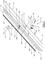
- a coupling strip 205 is fixed to the LED strip 105 (for example, by gluing the LED strip 105 onto the coupling strip 205 by means of a layer of adhesive material provided on a rear surface of its flexible printed circuit, denoted with the reference 210, opposite a front surface thereof where its LEDs are mounted, denoted with the reference 215), so as to obtain a corresponding lighting component 220.
- the coupling strip 205 as well is long, narrow and thin (for example, with the same length as the LED strip 105, width equal to or greater than the LED strip 105, and thickness of 0.2-0.8 mm).
- the coupling strip 205 is flexible, similarly to the LED strip 105 and in any case less rigid than the metal foil 110 is (for example, with a ratio between the bending stiffness of the coupling strip 205 and the bending stiffness of the metal foil 110 between 0.5 and 5, such as with the coupling strip 205 as well being not capable of self-sustaining in vertical).
- the coupling strip 205 and the metal foil 110 (or more generally, any support element) comprise a magnetic material (i.e. , which generates its own persistent magnetic field) and/or a ferromagnetic material (i . e ., which magnetizes when subject to an external magnetic field).
- the metal foil 110 is made of ferromagnetic material (such as of steel as indicated above)
- the coupling strip 205 is made of magnetic material (such as ferrite rubber magnet, also known as magnetic rubber).
- the magnetic material of the coupling strip 205 is arranged so that the corresponding magnetic moment is transverse to the metal foil 110 (for example, with the north pole and the south pole on a lower surface and on an upper surface, respectively, of the coupling strip 205 that are facing and opposite, respectively, the metal foil 110); in this way, when the lighting component 220 is arranged on the metal foil 110, a magnetic field generated by the coupling strip 205 completely encloses the metal foil 110. Therefore, the ferromagnetic material of the metal foil 110 magnetizes (with the south pole and the north pole on an upper surface and a lower surface, respectively, of the metal foil 110 that are facing and opposite, respectively, the coupling strip 205).
- a magnetic attraction force is generated between the coupling strip 205 and the metal foil 110 (perpendicularly thereto), so as to press the coupling strip 205 (and then the entire lighting component 220) against the metal foil 110.
- This magnetic attraction force (depending on the intensity of the magnetic field generated by the coupling strip 205, in turn depending on the characteristics of its magnetic material and on its size) has a value such as to enable detaching the lighting component 220 manually from the metal foil 110 (for example, corresponding to a pressure of the order of 0.01-0.1 N/cm 2 ); in this way, the lighting component 220 may be moved away from the metal foil 110 up to when the magnetic field generated by the coupling strip 205 no longer affects the metal foil 110 substantially, and thus the corresponding magnetic attraction force is negligible.
- the magnetic attraction force generates a corresponding sliding friction force between the coupling strip 205 and the metal foil 110 (parallel thereto), which friction force depends on such magnetic attraction force and on a coefficient of friction between the materials of the coupling strip 205 and of the metal foil 110.
- This friction force has a maximum value (in a rest condition corresponding to a coefficient of static friction) such as to lock the lighting component 220 firmly on the metal foil 110.
- this does not prevent the lighting component 220 to slide along the metal foil 110 when it is bent; this means that a corresponding tension applied to the lighting component 220 is higher than the friction force (for example, with the friction force of the order of 2.5-25 N).
- the sliding of the lighting component 220 along the metal foil 110 prevents (or at least substantially reduces) the application of any tension to the LED strip 105 when the metal foil 110 is bent, thereby limiting the risks of its damage.
- the lighting component 220 may be easily detached from the metal foil 110. This allows replacing the lighting component 220 (for example, when the LED strip 105 is broken) in a simple and fast way; moreover, in this way it is possible to avoid replacing its support element, with a corresponding reduction of the operating costs of the entire lighting apparatus.
- the choice of making the coupling strip 205 of the magnetic material and the metal foil 110 of the ferromagnetic material makes the latter simpler and easier to handle.
- the making of the coupling strip 205 of ferrite rubber magnet is very effective and inexpensive.
- FIG.3A-FIG.3B show a conceptual representation of the lighting apparatus according to an embodiment of the present disclosure in different configurations.
- the metal foil 110 and the lighting component 220 are bent so that the lighting component 220 is arranged inside a curve of the metal foil 110.
- the lighting component 220 has a radius of curvature lower than the metal foil 110 has. Therefore, the lighting component 220 has an angular extent greater than the metal foil 110 has, and then the lighting component 220 slides with respect to the metal foil 110 projecting outside it. This prevents (or at least substantially reduces) the risk of subjecting the LED strip 105 to any compression that might detach the lighting component 220 from the metal foil 110 (creating a ridge in the flexible printed circuit of its LED strip that might cause a detachment of the LEDs mounted thereon).
- the metal foil 110 and the lighting component 220 are bent so that the lighting component 220 is arranged outside a curve of the metal foil 110.
- the lighting component 220 has a radius of curvature higher than the metallic foil 110 has. Therefore, the lighting component 220 has an angular extent smaller than the metal foil 110 has, and then the lighting component 220 slides with respect to the metal foil 110 retracting inside it. This prevents (or at least substantially reduces) the risk of subjecting the lighting component 220 to any traction that might tear its LED strip.
- FIG.4 an exploded partial schematic representation is shown of the lighting apparatus according to an embodiment of the present disclosure.
- each base module the coupling strip 205 has the same length and a greater width (for example, 2-6 times) of the LED strip 105.
- the LED strip 105 is fastened at the centre (transversely) of the coupling strip 205.
- Two stiffening strips 405l and 405r are fastened on the entire remaining portion of the coupling strip 205 cleared by the LED strip 105 to the left and to the right thereof, respectively.
- Each stiffening strip 4051, 405r as well is long, narrow and thin (for example, with the same length of the LED strip 105, a width equal to 0.5-2 times that of the LED strip 105, and a thickness equal to 1-5 times that of the LED strip).
- the stiffening strips 4051,405r are flexible, but however more (bending) rigid than the LED strip 105 is (for example, with a ratio between the bending stiffness of the stiffening strips 4051,405r and the bending stiffness of the LED strip 105 between 2 and 5) but less (bending) rigid than the metal foil 110 is (for example, with a ratio between the bending stiffness of the stiffening strips 405l, 405r and the bending stiffness of the metal foil 110 between 0.1 and 0.5).
- the stiffening strips 4051,405r may be made of PVC, with a length of 5-100 cm, a width of 2-4 cm and a thickness of 1-2 mm.
- the stiffening strips 405l,405r increase the stability of the locking of the lighting component 220 on the metal foil 110.
- a slot 410l and 410r crosses each stiffening strip 405l and 405r, respectively, and the coupling strip 205 at each of their two longitudinal ends.
- the slots 410l,410r extend along the lighting component 220 (for example, with a width of 0.8-1 cm and a length of 3-8 cm).
- the through holes 415l,415r are narrower than the slots 410l,410r are (for example, with a width of 3-5 mm).
- Each (secondary) support 120 comprises a (fixing) plate 420 (for example, circular-shaped), which is used to fix the support 120 to the desired bearing structure (for example, by means of two dowels inserted through corresponding slots that cross them).
- a bracket 425 (for example, rectangular-shaped with rounded corners) extends perpendicularly from the centre of the plate 420, with a length substantially equal to the width of the metal foil 110.
- Two pairs of threaded pegs 430l and 430r (for example, inserts) corresponding to the pairs of through holes 415l and 415r, respectively, of two aligned base modules extend perpendicularly from the bracket 425 at each of its two side edges.
- the threaded pegs 430l,430r have a width matching the through-holes 415l,415r and a height greater than the thickness of the metal foil 110 (for example, 3-5 mm).
- Two pairs of (fixing) nuts 435l and 435r are provided for the two pairs of threaded pegs 430l and 430r, respectively.
- the support 120 further comprises a cover 440 (for example, cylindrical-shaped) for enclosing the bracket 425, which is equipped with a locking mechanism (for example, of snap type) on the plate 420.
- the cover 440 has a pair of slots 445 (of which only one visible in the figure) corresponding to the metal foil 110 and to the lighting component 220 of the two aligned base modules, which extend longitudinally from a free edge thereof. Similar considerations apply to the main support of the lighting apparatus, not shown in the figure (with the main support and a terminal secondary support that have only one slot).
- the lighting apparatus 100 is installed by fixing (to the wall in the example at issue) the main support (in correspondence to a mains power supply) and each required (secondary) support 120, according to the number of base modules, in a position corresponding to the desired shape of the lighting apparatus.
- the lighting component 220 is superimposed onto the metal foil 110 (remaining locked thereon by the magnetic attraction force between the coupling strip 205 and the metal foil 110), so that each slot 410l,410r is coaxial with the corresponding through hole 415l,415r.
- the longitudinal ends of the metal foil 110 with the lighting component 220 mounted thereon are supported on the brackets of a corresponding pair of adjacent supports 120 (or of the main support and a first support 120).
- each threaded peg 430l,430r crosses the corresponding through hole 415l,415r (projecting into the corresponding slot 410l,410r).
- Each nut 4351,435r is screwed onto the corresponding threaded peg 430l,430r (as described in detail below).
- the LED strip 105 is electrically connected to the LED strip 105 of the preceding base module (or to the power transformer in the main support).
- the cover 440 is fitted onto the bracket 425, so that the metal foil 110 with the lighting component 220 is inserted into the slot 445, until it is locked onto the plate 420.
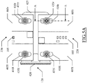
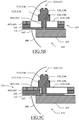
- FIG.5A-FIG.5D show a schematic representation of a detail of the lighting apparatus according to an embodiment of the present disclosure in various operative conditions.
- FIG.5A shows a top view of a generic installation support 120 (without cover) and FIG.5B shows a side cross-section view thereof (with the cover 440) along the section plane A-A of FIG.5A at a slot 405r (with similar considerations that apply to the slot 4051).
- each nut 435l,435r comprises a (sliding) shank 505l,505r (for example, with circular cross-section) having a size matching the width of the slot 410l,410r and a height corresponding to a thickness of the coupling strip 205 plus the stiffening strip 405l,405r.
- the nut 435r,435l further comprises a (driving) head 510l,510r (for example, slightly wider than the shank 505l,505r and provided with a recess for an Allen key).
- the shank 505l,505r and the head 510l,510r are separated by a (stop) collar 515l,515r larger than the width of the slot 410l,410r.
- a blind threaded hole 520l,520r (matching the corresponding threaded peg 430l,430r) extends upward from a base of the shank 505l,505r.
- the shank 505l,505r acts as guide peg for the sliding of the slot 410l,410r, while the collar 515l,515r acts as stop of the lighting component 220 against the metal foil 110 (without however preventing its sliding in parallel thereto).
- the lighting component 220 slides toward the outside of the metal foil 110 (to the right in the figure), thereby retracting into the support 120 through the slot 445; the shank 505l,505r guides this sliding of the slot 410l,410r (at most when its left end abuts against it).
- the nuts 435l,435r prevent any detachment of the lighting component 220 from the metal foil 110 (for example, when excessively bent). Furthermore, they maintain the correct alignment of the lighting component 220 with the metal foil 110 during their relative sliding (limiting their travel as well).
- an embodiment provides a lighting apparatus.
- the lighting apparatus comprises at least one flexible strip of one or more lighting elements, at least one support element for the strip of lighting elements, and coupling means for coupling the strip of lighting elements with the support element.
- the coupling means comprises at least one flexible coupling strip fixed to the strip of lighting elements.
- the coupling strip and the support element comprise a magnetic material and/or a ferromagnetic material (for exerting a magnetic attraction force between the coupling strip and the support element).
- the lighting apparatus may be of any type (for example, with any number of base modules, each arranged in any configuration such as straight, wavelike, S-like, U-like, O-like, ?-like, or in any combination thereof, with any support even all equal among them when the power transformer is remote).
- the lighting apparatus may comprise any number of strips of lighting elements, each one with any shape and size; furthermore, the strip of lighting elements may be of any type (for example, self-dissipating as well) and it may comprise different, additional or alternative components, with the lighting elements that may be in any number (one or more) and of any type (for example, LEDs, OLEDs, AMOLEDs, electroluminescence elements, ELs), with any operating characteristic, and in any position and number.
- the support element may be of any type (see below).
- the lighting apparatus may comprise any number of coupling strips (even with more strips of lighting elements for each coupling strip or vice-versa more coupling strips for each strip of lighting elements), each one with any shape and size.
- the strip of lighting elements and the coupling strip may be fixed to each other in any way (for example, mechanically or even with the coupling strip being an integral part of the strip of lighting elements).
- the flexibility of the strip of lighting elements and of the coupling strip may be defined by other values, either different or equal to each other (measured in any way).
- the magnetic material and the ferromagnetic material may be of any type (for example, of natural, ceramic, sintered type for the magnetic material and iron, cobalt, nickel, rare earths for the ferromagnetic material) and in any combination (see below).
- the coupling strip comprises said magnetic material and the support element comprises said ferromagnetic material.
- the possibility of making the support element of magnetic material and the coupling strip of ferromagnetic material, both of magnetic material (either equal or different), or in any combination of magnetic and ferromagnetic materials (for example, one in part of magnetic material and in part of ferromagnetic material and the other only of magnetic material, only of ferromagnetic material or of both of them) is not excluded.
- said magnetic material comprises ferrite rubber magnet.
- the magnetic material may comprise rubber (i.e ., a material with high elasticity, either of natural or synthetic type as defined in the standard ISO 1629) of any type (for example, NBR, HNBR, latex, CPE, TPE) that acts as a binder for magnetic particles of any type (either of natural or synthetic type); in any case, the magnetic particles may also be embedded in another more or less electrically insulating material (such as Kapton), and the possibility is not excluded of providing a strip entirely of magnetic material.
- rubber i.e ., a material with high elasticity, either of natural or synthetic type as defined in the standard ISO 1629
- any type for example, NBR, HNBR, latex, CPE, TPE
- the magnetic particles may also be embedded in another more or less electrically insulating material (such as Kapton), and the possibility is not excluded of providing a strip entirely of magnetic material.
- said support element comprises a thermally conductive material for dissipating heat produced by the strip of lighting elements in operation.
- the support element may be made of any thermally conductive material (for example, iron), with other values of thermal conductivity; in any case, the use of a support element of thermally insulating material is not excluded (for example, for self-dissipating LED strips).
- the support element comprises a flexible support foil; a bending stiffness of the support foil is higher than a bending stiffness of the strip of lighting elements and of the coupling strip.
- the support foil may have any shape and size (even equal to the strip of lighting elements) and its flexibility may be defined by other values (even measured in a different way), either in absolute terms or in relative terms with respect to the flexibility of the strip of lighting elements and of the coupling strip.
- the support foil may mount one or more strips of lighting elements only on a side thereof or on both; more generally, one or more strips of lighting elements may be mounted on a support element of any other type, being rigid as well (such as a cabinet, a reflector).
- the lighting apparatus further comprises a pair of stiffening strips fixed to the coupling strip alongside the strip of lighting elements; a bending stiffness of the stiffening strips is higher than a bending stiffness of the strip of lighting elements and of the coupling strip.
- the stiffening strips may have any shape and size, and may be made of any material (either electrically insulating or electrically conductive, such as Teflon or stainless steel, respectively).
- the flexibility of the stiffening strips may be defined by other values, even different between them, either in absolute terms or in relative with respect to the strip of lighting elements and to the coupling strip, and possibly in relative terms with respect to the support strip as well (measured in different ways as well).
- the stiffening strips may be arranged in another position, may be in different number (one or more than two), may be replaced with strips of pure ornament (with any bending stiffness even lower than that of the strip of lighting elements and of the coupling strip) or may be completely omitted.
- the coupling means comprises mechanical restraining means; the restraining means prevents at least in part a detachment of the coupling strip from the support element but allows a sliding at least partial of the coupling strip along the support element.
- the restraining means may prevent the detachment of different, additional or alternative parts of the coupling strip (up to its entirety), and may allow its complete or only partial sliding.
- such restraining means may be implemented in any way (see below), or may even be entirely omitted.
- the restraining means comprises the following elements at each end of the coupling strip. Particularly, one or more slots are provided, each one of them crossing the coupling strip. Moreover, one or more pegs are provided integral with the support element, each one of them crossing a corresponding one of the slots for guiding a sliding thereof; each peg comprises a stop collar of the coupling strip against the support element.
- the slots, the pegs and the collars may have any shape and size, and the collars may act either directly or indirectly (for example, via the stiffening strips) on the coupling strip. In any case, nothing prevents providing any number of such elements, arranged in any position (even when the stiffening strips are not provided); more generally, the same result may also be achieved with other elements (for example, lateral stopping clips).
- An embodiment provides a lighting component for use in such lighting apparatus; said lighting component comprises said at least one strip of lighting elements and said at least one coupling strip fixed to the strip of lighting elements.
- the lighting component may comprise any other element (such as the stiffening strips, the slots, a fuse). This lighting component lends itself to be made and put on the market as a stand-alone product, even for use in lighting apparatuses already existing.
- the lighting apparatus and the lighting component each has a different structure or comprises equivalent components (for example, of different materials), or it has other operative characteristics.
- every component thereof may be separated into more elements, or two or more components may be combined together into a single element; moreover, each component may be replicated to support the execution of the corresponding operations in parallel.
- any interaction between different components generally does not need to be continuous, and it may be either direct or indirect through one or more intermediaries.
- An embodiment provides a method for mounting a lighting apparatus.
- the method comprises the following steps. At least one flexible strip is provided of one or more lighting elements. At least one support element is provided for the strip of lighting elements. The strip of lighting elements is coupled with the support element. Said step of coupling comprises exerting a magnetic attraction force between at least one flexible coupling strip fixed to the strip of lighting elements and the support element; the coupling strip and the support element comprise a magnetic material and/or a ferromagnetic material for exerting said magnetic attraction force.
- these steps may be performed either during the preparation of the lighting apparatus (for example, in the factory) or during installation/maintenance (for example, at home).
Landscapes
- Engineering & Computer Science (AREA)
- General Engineering & Computer Science (AREA)
- Non-Portable Lighting Devices Or Systems Thereof (AREA)
Claims (14)
- Lampe souple du type en bande (100) comprenant au moins un module de base, chaque module de base comprenant au moins un ruban souple d'un ou plusieurs éléments d'éclairage (105), une feuille support souple (110) pour le ruban d'éléments d'éclairage (105) adaptée à prendre diverses formes et à maintenir ces formes de manière stable lorsque la lampe souple (100) est montée, deux supports d'installation (115, 120) agencés au niveau d'extrémité correspondantes de la feuille support (110) et du ruban d'éléments d'éclairage (105) pour fixation à une structure support de façon à supporter la lampe souple (100) dans une position permettant de donner à la feuille support (110) une forme souhaitée, et des moyens de couplage (205, 410l, 410r, 435l, 435r) pour coupler le ruban d'éléments d'éclairage (105) à la feuille support (110), les moyens de couplage (205, 410l, 410r, 435l, 435r) comprenant au moins un ruban de couplage souple (205) fixé au ruban d'éléments d'éclairage (105), le ruban de couplage (205) et la feuille support (110) comprenant un matériau magnétique et/ou un matériau ferromagnétique pour exercer une force d'attraction magnétique entre le ruban de couplage (205) et la feuille support (110), et des moyens de contrainte mécanique (410l, 410r, 435l, 435r) pour empêcher au moins en partie un détachement du ruban de couplage (205) de la feuille support (110) mais permettant un glissement au moins partiel du ruban de couplage (205) le long de la feuille support (110) lorsqu'elle est courbée pour un montage sur les supports d'installation (115, 120).
- Lampe souple (100) selon la revendication 1, dans laquelle le ruban de couplage (205) comprend le matériau magnétique et la feuille support (110) comprend le matériau ferromagnétique.
- Lampe souple (100) selon la revendication 1 ou 2, dans laquelle le matériau magnétique comprend du caoutchouc magnétique à ferrite.
- Lampe souple (100) selon l'une quelconque des revendications 1 à 3, dans laquelle la feuille support (110) comprend un matériau conducteur thermique pour dissiper la chaleur produite par le ruban d'éléments d'éclairage (105) en fonctionnement.
- Lampe souple (100) selon l'une quelconque des revendications 1 à 4, dans laquelle la feuille support (110) a une rigidité en flexion supérieure à la rigidité en flexion du ruban d'éléments d'éclairage (105) et du ruban de couplage (205).
- Lampe souple (100) selon l'une quelconque des revendications 1 à 5, comprenant en outre une paire de rubans raidisseurs (405l, 405r) fixée au ruban de couplage (205) le long du ruban d'éléments d'éclairage (105), la rigidité en flexion des rubans raidisseurs (405l, 405r) étant supérieure à la rigidité en flexion du ruban d'éléments d'éclairage (105) et du ruban de couplage (205).
- Lampe souple (100) selon l'une quelconque des revendications 1 à 6, dans laquelle la force d'attraction magnétique génère une force de friction en glissement entre le ruban de couplage (205) et la feuille support (110) de 2,5-25 N.
- Lampe souple (100) selon l'une quelconque des revendications 1 à 7, dans laquelle les moyens de contrainte (410l, 410r, 435l, 435r) sont agencés pour maintenir le composant d'éclairage (220) correctement aligné avec la feuille support (110) pendant leur glissement relatif.
- Lampe souple (100) selon l'une quelconque des revendications 1 à 8, dans laquelle les moyens de contrainte (410l, 410r, 435l, 435r) sont agencés pour limiter le déplacement du glissement du ruban de couplage (205) le long de la feuille support (110).
- Lampe souple (100) selon l'une quelconque des revendications 1 à 9, dans laquelle les moyens de contrainte (410l, 410r, 435l, 435r) comprennent, au niveau de chaque extrémité du ruban de couplage (205), une ou plusieurs fentes (410l ; 410r) traversant le ruban de couplage (205), et un ou plusieurs éléments de guidage (430l-435l, 430r-435r) d'une seule pièce avec la feuille support (110) traversant chacun l'une correspondante des fentes (410l ; 410r) pour guider un glissement de celui-ci, chaque élément de guidage (430l-435l, 430r-435r) comprenant un collier d'arrêt (515l, 515r) pour arrêter le ruban de couplage (205) contre la feuille support (110).
- Lampe souple (100) selon la revendication 10, dans laquelle chaque élément de guidage (430l-435l, 430r-435r) comprend une fiche filetée (430l, 430r) d'une seule pièce avec l'un correspondant des supports d'installation (115, 120), la fiche filetée (430l, 430r) traversant un trou traversant correspondant (415l, 415r) prévu au niveau d'une extrémité correspondante de la feuille support (110) et faisant saillie dans la fente correspondante (410l ; 410r), et un écrou (435l, 435r) destiné à être vissé sur la fiche filetée (430l, 430r), l'écrou (435l, 435r) comprenant le collier d'arrêt (515l, 515r) et une tige coulissante (505l, 505r) concordant avec la fente correspondante (410l ; 410r).
- Procédé pour monter une lampe souple du type en bande (100) comprenant, pour chacun d'au moins un module de base de la lampe souple (100) :prévoir au moins un ruban souple d'un ou plusieurs éléments d'éclairage (105),prévoir une feuille support souple (110) pour le ruban d'éléments d'éclairage (105),coupler le ruban d'éléments d'éclairage (105) avec la feuille support (110),fixer deux supports d'installation (115, 120) à une structure support, etagencer des extrémités correspondantes de la feuille support (110) avec le ruban d'éléments d'éclairage (105) au niveau des supports d'installation (115, 120) de manière à supporter la lampe souple (100) dans une position permettant de donner à la feuille support (110) une forme souhaitée, dans lequel le couplage comprend :exercer une force d'attraction magnétique entre au moins un ruban de couplage souple (205) fixé au ruban d'éléments d'éclairage (105) et la feuille support (110), le ruban de couplage (205) et la feuille support (110) comprenant un matériau magnétique et/ou un matériau ferromagnétique pour exercer la force d'attraction magnétique, etcontraindre mécaniquement le ruban de couplage (205) et la feuille support (110) pour empêcher au moins en partie un détachement du ruban de couplage (205) de la feuille support (110) mais en permettant un glissement au moins partiel du ruban de couplage (205) le long de la feuille support (110) lorsqu'elle est courbée pour un montage sur les supports d'installation (115, 120) .
- Procédé selon la revendication 12, dans lequel la contrainte mécanique comprend :
monter une ou plusieurs fentes (410l, 410r) traversant le ruban de couplage (205) au niveau de chaque extrémité de celui-ci en travers d'éléments de guidage correspondants (430l-435l, 430r-435r) d'une seule pièce avec la feuille support (110) pour guider un glissement de celui-ci, chaque élément de guidage (430l-435l, 430r-435r) comprenant un collier d'arrêt (515l, 515r) pour arrêter le ruban de couplage (205) contre la feuille support (110) . - Procédé selon la revendication 13, dans lequel le montage comprend, pour chaque élément de guidage (430l-435l, 430r-435r) :faire en sorte qu'une fiche filetée (430l, 430r) d'une seule pièce avec l'un correspondant des supports d'installation (115, 120) traverse un trou traversant correspondant (415l, 415r) prévu au niveau d'une extrémité correspondante de la feuille support (110) et fasse saillie dans la fente correspondante (410l, 410r), etvisser un écrou (435l, 435r) sur la fiche filetée (430l, 430r), l'écrou (435l, 435r) comprenant le collier d'arrêt (515l, 515r) et une tige coulissante (505l, 505r) concordant avec la fente correspondante (410l ; 410r).
Applications Claiming Priority (1)
| Application Number | Priority Date | Filing Date | Title |
|---|---|---|---|
| ITMI20140149 | 2014-02-03 |
Publications (2)
| Publication Number | Publication Date |
|---|---|
| EP2902697A1 EP2902697A1 (fr) | 2015-08-05 |
| EP2902697B1 true EP2902697B1 (fr) | 2018-07-04 |
Family
ID=50391283
Family Applications (1)
| Application Number | Title | Priority Date | Filing Date |
|---|---|---|---|
| EP15153610.9A Not-in-force EP2902697B1 (fr) | 2014-02-03 | 2015-02-03 | Dispositif d'éclairage formé de bande d'élement d'éclairage avec un couplage magnétique |
Country Status (1)
| Country | Link |
|---|---|
| EP (1) | EP2902697B1 (fr) |
Cited By (2)
| Publication number | Priority date | Publication date | Assignee | Title |
|---|---|---|---|---|
| US12187578B2 (en) | 2023-05-12 | 2025-01-07 | Otis Elevator Company | Protector for an elevator car |
| US12486968B2 (en) | 2023-08-30 | 2025-12-02 | Halco Lighting Technologies, Llc | Luminaire with replaceable LED board |
Families Citing this family (2)
| Publication number | Priority date | Publication date | Assignee | Title |
|---|---|---|---|---|
| US10655805B2 (en) * | 2015-12-02 | 2020-05-19 | Zyntony, Inc. | Multi-element flexible strap light |
| CN107911939B (zh) * | 2017-11-24 | 2024-05-10 | 惠州市鹏程电子科技有限公司 | 一种柔性印刷电路板 |
Family Cites Families (2)
| Publication number | Priority date | Publication date | Assignee | Title |
|---|---|---|---|---|
| DE102006031345A1 (de) * | 2006-07-06 | 2008-01-10 | Patent-Treuhand-Gesellschaft für elektrische Glühlampen mbH | Formflexibles Beleuchtungssystem |
| JP2012043756A (ja) * | 2010-08-23 | 2012-03-01 | Explore:Kk | 照明装置 |
-
2015
- 2015-02-03 EP EP15153610.9A patent/EP2902697B1/fr not_active Not-in-force
Non-Patent Citations (1)
| Title |
|---|
| None * |
Cited By (2)
| Publication number | Priority date | Publication date | Assignee | Title |
|---|---|---|---|---|
| US12187578B2 (en) | 2023-05-12 | 2025-01-07 | Otis Elevator Company | Protector for an elevator car |
| US12486968B2 (en) | 2023-08-30 | 2025-12-02 | Halco Lighting Technologies, Llc | Luminaire with replaceable LED board |
Also Published As
| Publication number | Publication date |
|---|---|
| EP2902697A1 (fr) | 2015-08-05 |
Similar Documents
| Publication | Publication Date | Title |
|---|---|---|
| CA2913679C (fr) | Ameliorations concernant des reseaux de lentilles | |
| US9072171B2 (en) | Circuit board mount for LED light | |
| KR101073439B1 (ko) | 엘이디 조명장치 | |
| US8419211B2 (en) | Lamp tube | |
| US20120293996A1 (en) | Multi-adjustable replacement led lighting element | |
| US20110248631A1 (en) | Led lamp set | |
| EP2902697B1 (fr) | Dispositif d'éclairage formé de bande d'élement d'éclairage avec un couplage magnétique | |
| WO2014008463A1 (fr) | Ensemble d'alimentation électrique pour tube lumineux à del | |
| US20120324772A1 (en) | Led light fixture with press-fit fixture housing heat sink | |
| US8899780B2 (en) | Configurable linear light assembly and associated methods | |
| US9039229B2 (en) | LED lamp fixture | |
| US20150109804A1 (en) | Apparatuses and methods for installing light modules | |
| CN203907320U (zh) | 一种led光源结构 | |
| KR200445125Y1 (ko) | 엘이디 조명기구의 커버 | |
| KR20110117523A (ko) | 매립형 led 조명 장치 | |
| KR101050278B1 (ko) | 엘이디 전구 | |
| KR100948313B1 (ko) | 엘이디 등기구 | |
| CN205592724U (zh) | 一种线条灯及其导轨 | |
| KR101024529B1 (ko) | 엘이디 등기구 | |
| KR102292001B1 (ko) | 쇼케이스용 조명 장치 | |
| US11287113B2 (en) | LED board mounting system for a fixture | |
| EP3141795A1 (fr) | Base monolithique de module d'éclairage à del et lampe comportant celle-ci | |
| CN209782308U (zh) | 一种无阴影的线性led灯具 | |
| KR200452874Y1 (ko) | Led 램프 | |
| KR101248748B1 (ko) | 조명용 led 패키지 탈부착 장치 |
Legal Events
| Date | Code | Title | Description |
|---|---|---|---|
| PUAI | Public reference made under article 153(3) epc to a published international application that has entered the european phase |
Free format text: ORIGINAL CODE: 0009012 |
|
| 17P | Request for examination filed |
Effective date: 20150203 |
|
| AK | Designated contracting states |
Kind code of ref document: A1 Designated state(s): AL AT BE BG CH CY CZ DE DK EE ES FI FR GB GR HR HU IE IS IT LI LT LU LV MC MK MT NL NO PL PT RO RS SE SI SK SM TR |
|
| AX | Request for extension of the european patent |
Extension state: BA ME |
|
| 17P | Request for examination filed |
Effective date: 20160203 |
|
| RBV | Designated contracting states (corrected) |
Designated state(s): AL AT BE BG CH CY CZ DE DK EE ES FI FR GB GR HR HU IE IS IT LI LT LU LV MC MK MT NL NO PL PT RO RS SE SI SK SM TR |
|
| STAA | Information on the status of an ep patent application or granted ep patent |
Free format text: STATUS: EXAMINATION IS IN PROGRESS |
|
| 17Q | First examination report despatched |
Effective date: 20161201 |
|
| REG | Reference to a national code |
Ref country code: DE Ref legal event code: R079 Ref document number: 602015012868 Country of ref document: DE Free format text: PREVIOUS MAIN CLASS: F21S0004000000 Ipc: F21S0004240000 |
|
| RIC1 | Information provided on ipc code assigned before grant |
Ipc: F21Y 101/00 20160101ALN20171124BHEP Ipc: F21S 4/24 20160101AFI20171124BHEP Ipc: F21V 19/00 20060101ALI20171124BHEP Ipc: F21Y 103/10 20160101ALN20171124BHEP Ipc: F21Y 115/10 20160101ALN20171124BHEP Ipc: F21V 17/10 20060101ALN20171124BHEP Ipc: F21V 21/005 20060101ALN20171124BHEP |
|
| RIC1 | Information provided on ipc code assigned before grant |
Ipc: F21V 21/005 20060101ALN20171211BHEP Ipc: F21S 4/24 20160101AFI20171211BHEP Ipc: F21V 17/10 20060101ALN20171211BHEP Ipc: F21Y 115/10 20160101ALN20171211BHEP Ipc: F21Y 103/10 20160101ALN20171211BHEP Ipc: F21V 19/00 20060101ALI20171211BHEP Ipc: F21Y 101/00 20160101ALN20171211BHEP |
|
| GRAP | Despatch of communication of intention to grant a patent |
Free format text: ORIGINAL CODE: EPIDOSNIGR1 |
|
| STAA | Information on the status of an ep patent application or granted ep patent |
Free format text: STATUS: GRANT OF PATENT IS INTENDED |
|
| INTG | Intention to grant announced |
Effective date: 20180122 |
|
| GRAS | Grant fee paid |
Free format text: ORIGINAL CODE: EPIDOSNIGR3 |
|
| GRAA | (expected) grant |
Free format text: ORIGINAL CODE: 0009210 |
|
| STAA | Information on the status of an ep patent application or granted ep patent |
Free format text: STATUS: THE PATENT HAS BEEN GRANTED |
|
| AK | Designated contracting states |
Kind code of ref document: B1 Designated state(s): AL AT BE BG CH CY CZ DE DK EE ES FI FR GB GR HR HU IE IS IT LI LT LU LV MC MK MT NL NO PL PT RO RS SE SI SK SM TR |
|
| REG | Reference to a national code |
Ref country code: GB Ref legal event code: FG4D |
|
| REG | Reference to a national code |
Ref country code: CH Ref legal event code: EP |
|
| REG | Reference to a national code |
Ref country code: AT Ref legal event code: REF Ref document number: 1014904 Country of ref document: AT Kind code of ref document: T Effective date: 20180715 |
|
| REG | Reference to a national code |
Ref country code: IE Ref legal event code: FG4D |
|
| REG | Reference to a national code |
Ref country code: DE Ref legal event code: R096 Ref document number: 602015012868 Country of ref document: DE |
|
| REG | Reference to a national code |
Ref country code: NL Ref legal event code: MP Effective date: 20180704 |
|
| REG | Reference to a national code |
Ref country code: LT Ref legal event code: MG4D |
|
| REG | Reference to a national code |
Ref country code: AT Ref legal event code: MK05 Ref document number: 1014904 Country of ref document: AT Kind code of ref document: T Effective date: 20180704 |
|
| PG25 | Lapsed in a contracting state [announced via postgrant information from national office to epo] |
Ref country code: NL Free format text: LAPSE BECAUSE OF FAILURE TO SUBMIT A TRANSLATION OF THE DESCRIPTION OR TO PAY THE FEE WITHIN THE PRESCRIBED TIME-LIMIT Effective date: 20180704 |
|
| PG25 | Lapsed in a contracting state [announced via postgrant information from national office to epo] |
Ref country code: RS Free format text: LAPSE BECAUSE OF FAILURE TO SUBMIT A TRANSLATION OF THE DESCRIPTION OR TO PAY THE FEE WITHIN THE PRESCRIBED TIME-LIMIT Effective date: 20180704 Ref country code: IS Free format text: LAPSE BECAUSE OF FAILURE TO SUBMIT A TRANSLATION OF THE DESCRIPTION OR TO PAY THE FEE WITHIN THE PRESCRIBED TIME-LIMIT Effective date: 20181104 Ref country code: PL Free format text: LAPSE BECAUSE OF FAILURE TO SUBMIT A TRANSLATION OF THE DESCRIPTION OR TO PAY THE FEE WITHIN THE PRESCRIBED TIME-LIMIT Effective date: 20180704 Ref country code: AT Free format text: LAPSE BECAUSE OF FAILURE TO SUBMIT A TRANSLATION OF THE DESCRIPTION OR TO PAY THE FEE WITHIN THE PRESCRIBED TIME-LIMIT Effective date: 20180704 Ref country code: BG Free format text: LAPSE BECAUSE OF FAILURE TO SUBMIT A TRANSLATION OF THE DESCRIPTION OR TO PAY THE FEE WITHIN THE PRESCRIBED TIME-LIMIT Effective date: 20181004 Ref country code: CZ Free format text: LAPSE BECAUSE OF FAILURE TO SUBMIT A TRANSLATION OF THE DESCRIPTION OR TO PAY THE FEE WITHIN THE PRESCRIBED TIME-LIMIT Effective date: 20180704 Ref country code: LT Free format text: LAPSE BECAUSE OF FAILURE TO SUBMIT A TRANSLATION OF THE DESCRIPTION OR TO PAY THE FEE WITHIN THE PRESCRIBED TIME-LIMIT Effective date: 20180704 Ref country code: FI Free format text: LAPSE BECAUSE OF FAILURE TO SUBMIT A TRANSLATION OF THE DESCRIPTION OR TO PAY THE FEE WITHIN THE PRESCRIBED TIME-LIMIT Effective date: 20180704 Ref country code: GR Free format text: LAPSE BECAUSE OF FAILURE TO SUBMIT A TRANSLATION OF THE DESCRIPTION OR TO PAY THE FEE WITHIN THE PRESCRIBED TIME-LIMIT Effective date: 20181005 Ref country code: NO Free format text: LAPSE BECAUSE OF FAILURE TO SUBMIT A TRANSLATION OF THE DESCRIPTION OR TO PAY THE FEE WITHIN THE PRESCRIBED TIME-LIMIT Effective date: 20181004 Ref country code: SE Free format text: LAPSE BECAUSE OF FAILURE TO SUBMIT A TRANSLATION OF THE DESCRIPTION OR TO PAY THE FEE WITHIN THE PRESCRIBED TIME-LIMIT Effective date: 20180704 |
|
| REG | Reference to a national code |
Ref country code: CH Ref legal event code: PK Free format text: RETTIFICHE |
|
| RIC2 | Information provided on ipc code assigned after grant |
Ipc: F21V 21/005 20060101ALN20171211BHEP Ipc: F21Y 115/10 20160101ALN20171211BHEP Ipc: F21V 17/10 20060101ALN20171211BHEP Ipc: F21Y 101/00 20160101ALN20171211BHEP Ipc: F21Y 103/10 20160101ALN20171211BHEP Ipc: F21V 19/00 20060101ALI20171211BHEP Ipc: F21S 4/24 20160101AFI20171211BHEP |
|
| PG25 | Lapsed in a contracting state [announced via postgrant information from national office to epo] |
Ref country code: HR Free format text: LAPSE BECAUSE OF FAILURE TO SUBMIT A TRANSLATION OF THE DESCRIPTION OR TO PAY THE FEE WITHIN THE PRESCRIBED TIME-LIMIT Effective date: 20180704 Ref country code: ES Free format text: LAPSE BECAUSE OF FAILURE TO SUBMIT A TRANSLATION OF THE DESCRIPTION OR TO PAY THE FEE WITHIN THE PRESCRIBED TIME-LIMIT Effective date: 20180704 Ref country code: AL Free format text: LAPSE BECAUSE OF FAILURE TO SUBMIT A TRANSLATION OF THE DESCRIPTION OR TO PAY THE FEE WITHIN THE PRESCRIBED TIME-LIMIT Effective date: 20180704 Ref country code: LV Free format text: LAPSE BECAUSE OF FAILURE TO SUBMIT A TRANSLATION OF THE DESCRIPTION OR TO PAY THE FEE WITHIN THE PRESCRIBED TIME-LIMIT Effective date: 20180704 |
|
| REG | Reference to a national code |
Ref country code: DE Ref legal event code: R097 Ref document number: 602015012868 Country of ref document: DE |
|
| PG25 | Lapsed in a contracting state [announced via postgrant information from national office to epo] |
Ref country code: IT Free format text: LAPSE BECAUSE OF FAILURE TO SUBMIT A TRANSLATION OF THE DESCRIPTION OR TO PAY THE FEE WITHIN THE PRESCRIBED TIME-LIMIT Effective date: 20180704 Ref country code: RO Free format text: LAPSE BECAUSE OF FAILURE TO SUBMIT A TRANSLATION OF THE DESCRIPTION OR TO PAY THE FEE WITHIN THE PRESCRIBED TIME-LIMIT Effective date: 20180704 Ref country code: EE Free format text: LAPSE BECAUSE OF FAILURE TO SUBMIT A TRANSLATION OF THE DESCRIPTION OR TO PAY THE FEE WITHIN THE PRESCRIBED TIME-LIMIT Effective date: 20180704 |
|
| PLBE | No opposition filed within time limit |
Free format text: ORIGINAL CODE: 0009261 |
|
| STAA | Information on the status of an ep patent application or granted ep patent |
Free format text: STATUS: NO OPPOSITION FILED WITHIN TIME LIMIT |
|
| PG25 | Lapsed in a contracting state [announced via postgrant information from national office to epo] |
Ref country code: SM Free format text: LAPSE BECAUSE OF FAILURE TO SUBMIT A TRANSLATION OF THE DESCRIPTION OR TO PAY THE FEE WITHIN THE PRESCRIBED TIME-LIMIT Effective date: 20180704 Ref country code: SK Free format text: LAPSE BECAUSE OF FAILURE TO SUBMIT A TRANSLATION OF THE DESCRIPTION OR TO PAY THE FEE WITHIN THE PRESCRIBED TIME-LIMIT Effective date: 20180704 Ref country code: DK Free format text: LAPSE BECAUSE OF FAILURE TO SUBMIT A TRANSLATION OF THE DESCRIPTION OR TO PAY THE FEE WITHIN THE PRESCRIBED TIME-LIMIT Effective date: 20180704 |
|
| 26N | No opposition filed |
Effective date: 20190405 |
|
| PG25 | Lapsed in a contracting state [announced via postgrant information from national office to epo] |
Ref country code: SI Free format text: LAPSE BECAUSE OF FAILURE TO SUBMIT A TRANSLATION OF THE DESCRIPTION OR TO PAY THE FEE WITHIN THE PRESCRIBED TIME-LIMIT Effective date: 20180704 |
|
| REG | Reference to a national code |
Ref country code: DE Ref legal event code: R119 Ref document number: 602015012868 Country of ref document: DE |
|
| REG | Reference to a national code |
Ref country code: CH Ref legal event code: PL |
|
| GBPC | Gb: european patent ceased through non-payment of renewal fee |
Effective date: 20190203 |
|
| PG25 | Lapsed in a contracting state [announced via postgrant information from national office to epo] |
Ref country code: MC Free format text: LAPSE BECAUSE OF FAILURE TO SUBMIT A TRANSLATION OF THE DESCRIPTION OR TO PAY THE FEE WITHIN THE PRESCRIBED TIME-LIMIT Effective date: 20180704 Ref country code: LU Free format text: LAPSE BECAUSE OF NON-PAYMENT OF DUE FEES Effective date: 20190203 |
|
| REG | Reference to a national code |
Ref country code: BE Ref legal event code: MM Effective date: 20190228 |
|
| REG | Reference to a national code |
Ref country code: IE Ref legal event code: MM4A |
|
| PG25 | Lapsed in a contracting state [announced via postgrant information from national office to epo] |
Ref country code: CH Free format text: LAPSE BECAUSE OF NON-PAYMENT OF DUE FEES Effective date: 20190228 Ref country code: LI Free format text: LAPSE BECAUSE OF NON-PAYMENT OF DUE FEES Effective date: 20190228 |
|
| PG25 | Lapsed in a contracting state [announced via postgrant information from national office to epo] |
Ref country code: GB Free format text: LAPSE BECAUSE OF NON-PAYMENT OF DUE FEES Effective date: 20190203 Ref country code: DE Free format text: LAPSE BECAUSE OF NON-PAYMENT OF DUE FEES Effective date: 20190903 Ref country code: IE Free format text: LAPSE BECAUSE OF NON-PAYMENT OF DUE FEES Effective date: 20190203 |
|
| PG25 | Lapsed in a contracting state [announced via postgrant information from national office to epo] |
Ref country code: FR Free format text: LAPSE BECAUSE OF NON-PAYMENT OF DUE FEES Effective date: 20190228 Ref country code: BE Free format text: LAPSE BECAUSE OF NON-PAYMENT OF DUE FEES Effective date: 20190228 |
|
| PG25 | Lapsed in a contracting state [announced via postgrant information from national office to epo] |
Ref country code: TR Free format text: LAPSE BECAUSE OF FAILURE TO SUBMIT A TRANSLATION OF THE DESCRIPTION OR TO PAY THE FEE WITHIN THE PRESCRIBED TIME-LIMIT Effective date: 20180704 |
|
| PG25 | Lapsed in a contracting state [announced via postgrant information from national office to epo] |
Ref country code: PT Free format text: LAPSE BECAUSE OF FAILURE TO SUBMIT A TRANSLATION OF THE DESCRIPTION OR TO PAY THE FEE WITHIN THE PRESCRIBED TIME-LIMIT Effective date: 20181104 Ref country code: MT Free format text: LAPSE BECAUSE OF NON-PAYMENT OF DUE FEES Effective date: 20190203 |
|
| PG25 | Lapsed in a contracting state [announced via postgrant information from national office to epo] |
Ref country code: CY Free format text: LAPSE BECAUSE OF FAILURE TO SUBMIT A TRANSLATION OF THE DESCRIPTION OR TO PAY THE FEE WITHIN THE PRESCRIBED TIME-LIMIT Effective date: 20180704 |
|
| PG25 | Lapsed in a contracting state [announced via postgrant information from national office to epo] |
Ref country code: HU Free format text: LAPSE BECAUSE OF FAILURE TO SUBMIT A TRANSLATION OF THE DESCRIPTION OR TO PAY THE FEE WITHIN THE PRESCRIBED TIME-LIMIT; INVALID AB INITIO Effective date: 20150203 |
|
| PG25 | Lapsed in a contracting state [announced via postgrant information from national office to epo] |
Ref country code: MK Free format text: LAPSE BECAUSE OF FAILURE TO SUBMIT A TRANSLATION OF THE DESCRIPTION OR TO PAY THE FEE WITHIN THE PRESCRIBED TIME-LIMIT Effective date: 20180704 |