EP2902803B1 - Capteur de proximité et procédé de détection de proximité utilisant un capteur de vision fondé sur des évènements - Google Patents
Capteur de proximité et procédé de détection de proximité utilisant un capteur de vision fondé sur des évènements Download PDFInfo
- Publication number
- EP2902803B1 EP2902803B1 EP13842660.6A EP13842660A EP2902803B1 EP 2902803 B1 EP2902803 B1 EP 2902803B1 EP 13842660 A EP13842660 A EP 13842660A EP 2902803 B1 EP2902803 B1 EP 2902803B1
- Authority
- EP
- European Patent Office
- Prior art keywords
- proximity sensor
- distance
- light
- light source
- output
- Prior art date
- Legal status (The legal status is an assumption and is not a legal conclusion. Google has not performed a legal analysis and makes no representation as to the accuracy of the status listed.)
- Active
Links
Images



Classifications
-
- G—PHYSICS
- G01—MEASURING; TESTING
- G01S—RADIO DIRECTION-FINDING; RADIO NAVIGATION; DETERMINING DISTANCE OR VELOCITY BY USE OF RADIO WAVES; LOCATING OR PRESENCE-DETECTING BY USE OF THE REFLECTION OR RERADIATION OF RADIO WAVES; ANALOGOUS ARRANGEMENTS USING OTHER WAVES
- G01S17/00—Systems using the reflection or reradiation of electromagnetic waves other than radio waves, e.g. lidar systems
- G01S17/02—Systems using the reflection of electromagnetic waves other than radio waves
- G01S17/06—Systems determining position data of a target
-
- G—PHYSICS
- G01—MEASURING; TESTING
- G01S—RADIO DIRECTION-FINDING; RADIO NAVIGATION; DETERMINING DISTANCE OR VELOCITY BY USE OF RADIO WAVES; LOCATING OR PRESENCE-DETECTING BY USE OF THE REFLECTION OR RERADIATION OF RADIO WAVES; ANALOGOUS ARRANGEMENTS USING OTHER WAVES
- G01S17/00—Systems using the reflection or reradiation of electromagnetic waves other than radio waves, e.g. lidar systems
- G01S17/88—Lidar systems specially adapted for specific applications
-
- G—PHYSICS
- G01—MEASURING; TESTING
- G01S—RADIO DIRECTION-FINDING; RADIO NAVIGATION; DETERMINING DISTANCE OR VELOCITY BY USE OF RADIO WAVES; LOCATING OR PRESENCE-DETECTING BY USE OF THE REFLECTION OR RERADIATION OF RADIO WAVES; ANALOGOUS ARRANGEMENTS USING OTHER WAVES
- G01S7/00—Details of systems according to groups G01S13/00, G01S15/00, G01S17/00
- G01S7/48—Details of systems according to groups G01S13/00, G01S15/00, G01S17/00 of systems according to group G01S17/00
- G01S7/481—Constructional features, e.g. arrangements of optical elements
-
- G—PHYSICS
- G01—MEASURING; TESTING
- G01S—RADIO DIRECTION-FINDING; RADIO NAVIGATION; DETERMINING DISTANCE OR VELOCITY BY USE OF RADIO WAVES; LOCATING OR PRESENCE-DETECTING BY USE OF THE REFLECTION OR RERADIATION OF RADIO WAVES; ANALOGOUS ARRANGEMENTS USING OTHER WAVES
- G01S17/00—Systems using the reflection or reradiation of electromagnetic waves other than radio waves, e.g. lidar systems
- G01S17/02—Systems using the reflection of electromagnetic waves other than radio waves
- G01S17/06—Systems determining position data of a target
- G01S17/08—Systems determining position data of a target for measuring distance only
-
- G—PHYSICS
- G01—MEASURING; TESTING
- G01S—RADIO DIRECTION-FINDING; RADIO NAVIGATION; DETERMINING DISTANCE OR VELOCITY BY USE OF RADIO WAVES; LOCATING OR PRESENCE-DETECTING BY USE OF THE REFLECTION OR RERADIATION OF RADIO WAVES; ANALOGOUS ARRANGEMENTS USING OTHER WAVES
- G01S17/00—Systems using the reflection or reradiation of electromagnetic waves other than radio waves, e.g. lidar systems
- G01S17/02—Systems using the reflection of electromagnetic waves other than radio waves
- G01S17/06—Systems determining position data of a target
- G01S17/46—Indirect determination of position data
-
- G—PHYSICS
- G01—MEASURING; TESTING
- G01S—RADIO DIRECTION-FINDING; RADIO NAVIGATION; DETERMINING DISTANCE OR VELOCITY BY USE OF RADIO WAVES; LOCATING OR PRESENCE-DETECTING BY USE OF THE REFLECTION OR RERADIATION OF RADIO WAVES; ANALOGOUS ARRANGEMENTS USING OTHER WAVES
- G01S17/00—Systems using the reflection or reradiation of electromagnetic waves other than radio waves, e.g. lidar systems
- G01S17/02—Systems using the reflection of electromagnetic waves other than radio waves
- G01S17/50—Systems of measurement based on relative movement of target
-
- G—PHYSICS
- G01—MEASURING; TESTING
- G01S—RADIO DIRECTION-FINDING; RADIO NAVIGATION; DETERMINING DISTANCE OR VELOCITY BY USE OF RADIO WAVES; LOCATING OR PRESENCE-DETECTING BY USE OF THE REFLECTION OR RERADIATION OF RADIO WAVES; ANALOGOUS ARRANGEMENTS USING OTHER WAVES
- G01S7/00—Details of systems according to groups G01S13/00, G01S15/00, G01S17/00
- G01S7/48—Details of systems according to groups G01S13/00, G01S15/00, G01S17/00 of systems according to group G01S17/00
- G01S7/491—Details of non-pulse systems
- G01S7/493—Extracting wanted echo signals
Definitions
- the following description relates to a proximity sensor and a proximity sensing method using an event-based vision sensor, and more particularly, to a proximity sensor and a proximity sensing method which identify a position in which an output light is reflected from an object by the event-based vision sensor and measure a distance between the object and the proximity sensor using the identified position.
- a proximity sensor outputs an output light for a predetermined time and determines proximity of an object using a sum total of reflected light reflected from the object.
- Conventional proximity sensors are sensitive to environmental changes and subject to noise. For example, when the sum total of reflected light is increased due to a reflected light related to light output by other light sources, such as the sun or a fluorescent lamp, accuracy of determining the proximity may be reduced.
- the conventional proximity sensors use the sum total of reflected light, a distance between the object and the proximity sensor may not be measured.
- a proximity sensor including a point identification (ID) unit or a region identification (ID) unit wherein the sensor exhibits in combination features of a respective one of the appended independent sensor claims.
- ID point identification
- ID region identification
- further methods are provided, exhibiting in combination features of a respective one of the appended independent method claims.
- FIG. 1 is a diagram illustrating a proximity sensor 100 according to an exemplary embodiment.
- the proximity sensor 100 may determine a distance between an object 102 and the proximity sensor 100 using a position of a point at which an output light output from a light source 101 is reflected from the object 102.
- the proximity sensor 100 may be an event-based vision sensor, such as a design vision sensor (DVS).
- the light source 101 may be a focused light source of which an output light is not scattered according to a distance.
- the light source 101 may be a light amplification by stimulated emission of radiation (LASER).
- the light source 101 may change intensity of the output light according to at least one of a predetermined time interval, a particular condition, and a user operation.
- the particular condition may be set so that the light source 101 changes the intensity of the output light when a distance between the object 102 and the proximity sensor 100 is unchanged for at least a predetermined time.
- the object 102 may be any type of object, such as a user or other object.
- the proximity sensor 100 may include a pattern detection unit 110, an image taking unit 120, a point identification (ID) unit, and a distance determination unit 140.
- the pattern detection unit 110 may detect an event pattern of a reflected light, which is the output light of the light source 101 reflected from the object 102.
- the event pattern may be designed in such a manner that intensity of the reflected light is increased or decreased by a predetermined amount or a predetermined rate according to time.
- the intensity of the reflected light may be increased or decreased according to the distance between the proximity sensor 100 and the object 102. For example, as the distance between the proximity sensor 100 and the object 102 is reduced, a proportion of the reflected light receivable by the pattern detection unit 110 out of the output light reflected from the object 102 may be increased. Accordingly, as the distance between the proximity sensor 100 and the object 102 is decreased, the intensity of the reflected light detected by the pattern detection unit 110 may be increased.
- the proportion of the reflected light receivable by the pattern detection unit 110 out of the output light reflected from the object 102 may be decreased. Accordingly, as the distance between the proximity sensor 100 and the object 102 is increased, the intensity of the reflected light detected by the pattern detection unit 110 may be decreased.
- the event pattern may correspond to a pattern in which the intensity of the output light is changed. For example, at a time point at which the light source 101 increases the intensity of the output light by a predetermined amount or a predetermined rate, the intensity of the reflected light may correspondingly increase in the event pattern detected by the pattern detection unit 110.
- the pattern detection unit 110 may be a temporal contrast optical sensor adapted to detect a change in the intensity of light incident to a pixel of an image and thereby output events.
- the temporal contrast optical sensor may output 'on events' when the intensity of light incident to the pixel is increased by a predetermined amount or a predetermined rate, and output 'off events' when the intensity of light incident to the pixel is decreased by a predetermined amount or a predetermined rate.
- the temporal contrast optical sensor may operate asynchronously without a frame, and may have time resolution of about 10 micro seconds ( ⁇ s) or less. Accordingly, the change of the intensity of light of the event pattern of light reflected from the object may be compared to the change of the intensity of the light output by the light source to determine whether the change of the intensity of the light reflected from the object corresponds to the change of the intensity of the light output by the light source to distinguish the reflected light from noise.
- the image taking unit 120 may take an image including the object 102.
- the image taken by the image taking unit 120 may include a point at which the output light of the light source 101 is reflected by the object 102.
- An output light from another light source may be reflected from the object 102 according to a movement of the object 102 or other various factors. For example, when the object 102 is disposed under a fluorescent lamp or the sun, output light of the fluorescent lamp or the sun may also be reflected from the object 102.
- the image taken by the image taking unit 120 may include the point at which the output light of the light source 101 is reflected from the object 102 and a noise generated by the output light of another light source reflected by the object 102.
- Another object may intervene between the object 102 and the proximity sensor 100.
- a point at which the output light is reflected by the other object may be the noise.
- the output light may be reflected by the hair and therefore the point may be disposed at the hair.
- the hair since the hair is not the object of proximity determination, and the point disposed on the hair may be considered as the noise.
- the image taken by the image taking unit 120 will be described in detail with reference to FIGS. 2 and 3 .
- the point ID unit 130 may identify the point at which the output light is reflected from the object 102 in the image taken by the image taking unit 120.
- the point ID unit 130 may easily recognize the point.
- the point ID unit 130 may distinguish the point and the noise generated by another light source in the image taken by the image taking unit 120.
- the event pattern of the reflected light reflected at the point may correspond to a temporal change of the output light of the light source 101.
- the intensity of the reflected light reflected from the point may be changed. Therefore, the event pattern of the reflected light may include 'on events' at the time point at which the light source 101 changes the intensity of the output light, and such events may be compared to corresponding events of the light source 101.
- the event pattern of the reflected light reflected at the noise is determined according to the change in the intensity of the output light output from the other light source or according to whether the output light output from the other light source is interrupted before reaching the object 102. Therefore, the event pattern may not correspond to the temporal change of the output light of the other light source.
- the point ID unit 130 may identify at least one point at which the output light is reflected and the noise in the image taken by the image taking unit 120, and distinguish the point from the noise by comparing the event pattern of the identified point or the noise with the temporal change of the output light of the light source 101.
- the point ID unit 130 may store event patterns of the identified points. When the pattern detection unit 110 detects a new pattern, the point ID unit 130 may compare the new pattern with the stored event patterns, thereby controlling the noise.
- the distance determination unit 140 may determine the distance between the object 102 and the proximity sensor 100 based on a position of the point identified by the point ID unit 130.
- the point when the output light is output at a predetermined angle toward the object 102, the point may be moved in a direction away from the light source 101 according to an increase in the distance between the object 102 and the proximity sensor 100.
- the distance determination unit 140 may identify a direction corresponding to the position of the light source 101 on the image using a distance between the proximity sensor 100 and the light source 101, and determine the distance between the object 102 and the proximity sensor 100 using a distance between the position of the point and a side of the image corresponding to the identified direction.
- the distance between the position of the point and the side of the image corresponding to the identified direction may be increased even though the distance between the object 102 and the proximity sensor 100 is constant.
- the distance determination unit 140 may determine the distance between the object 102 and the proximity sensor 100 using the angle at which the output light is output toward the object 102, the distance between the proximity sensor 100 and the light source 101, and the position of the point.
- a process of determining the distance between the object 102 and the proximity sensor 100 by the distance determination unit 140 will be described in detail with reference to FIG. 2 .
- the distance determination unit 140 may identify a movement direction of the point by comparing images successively taken by the image taking unit 120, and determine whether the object 102 approximates the proximity sensor 100 based on the movement direction of the point. In detail, the distance determination unit 140 may determine that the object 102 approximates the proximity sensor 100 when the movement direction of the region corresponds to a direction of the light source 101 with respect to the proximity sensor 100. Also, the distance determination unit 140 may determine that the object 102 is separated from the proximity sensor 100 when the movement direction of the point is opposite to the direction of the light source 101 with respect to the proximity sensor 100.
- the intensity of the reflected light is increased and therefore a number of events output by the pattern detection unit 110 may be increased. That is, the number of events output by the pattern detection unit 110 may be inversely proportional to the distance between the object 102 and the proximity sensor 100.
- the distance determination unit 140 may determine proximity of the object 102 using a number of events that correspond to the temporal change of the output light among the event patterns detected by the pattern detection unit 110.
- FIG. 2 is a diagram illustrating an operation of the proximity sensor 100 according to an exemplary embodiment.
- FIG. 2 is a top view of the proximity sensor 100. That is, the light source 101 may be disposed to the right of the proximity sensor 100.
- the light source 101 may output an output light 200 at an angle ⁇ toward the object 102 as shown in FIG. 2 .
- the output light 200 may be reflected at a point 211, and the proximity sensor 100 may detect an event pattern of a reflected light 212 reflected from the point 211.
- the point 211 may be included in an image 213 taken by the image taking unit 120.
- the distance determination unit 140 may determine dX denoting the distance 210 between the object 102 and the proximity sensor 100 using Equation 1.
- dX d 1 ⁇ sRA + sLA 1 + tan ⁇ ⁇ sLA ⁇ 1 ⁇ tan ⁇ ⁇ sRA
- d1 denotes the distance between the proximity sensor 100 and the light source 101
- sRA denotes a distance between a right side of the image 213 and the point 211
- sLA denotes a distance between a left side of the image 213 and the point 211.
- the output light 200 may be reflected at a point 221, and the proximity sensor 100 may detect an event pattern of a reflected light 222 reflected from the point 221.
- the point 221 may be included in an image 223 taken by the image taking unit 120.
- the output light 200 may be moved to the left more than when reflected from the point 211, brought into contact with the object 102, and reflected at the point 221. Therefore, the point 221 may be disposed on a more left than the point 211 as shown in FIG. 2 .
- the distance determination unit 140 may determine dX denoting the distance 220 between the object 102 and the proximity sensor 100, by substituting a distance sRB between a right side of the image 223 and the point 221 and a distance sLB between a left side of the image 223 and the point 211, for the distances sRA and sLA of Equation 1.
- FIG. 3 is a diagram illustrating an operation of a proximity sensor according to another exemplary embodiment.
- FIG. 3 is a top view showing the operation of the proximity sensor when an output light 300 is output orthogonally toward the object 102.
- the light source 101 may output the output light 300 at the angle ⁇ toward the object 102.
- the output light 300 may be reflected at a point 311 and the proximity sensor 100 may detect an event pattern of a reflected light 312 reflected from the point 311.
- the point 311 may be included in an image 313 taken by the image taking unit 120.
- the output light 300 may be reflected at a point 321 and the proximity sensor 100 may detect an event pattern of a reflected light 322 reflected from the point 321.
- the point 321 may be included in an image 323 taken by the image taking unit 120.
- the output light 300 may be reflected at a point 331 and the proximity sensor 100 may detect an event pattern of a reflected light 332 reflected from the point 331.
- the point 331 may be included in an image 333 taken by the image taking unit 120.
- positions of the points 311, 321, and 331 may be equal in the object 102.
- the image taken by the image taking unit 120 may include a background or another object other than the object 102 as the distance between the object 102 and the proximity sensor 100 is increased.
- the image 313 shows the object 102 in a large area.
- a size of the object 102 displayed is reduced in comparison to in the image 313.
- a distance 314 from a center of the object 102 to a point is uniform in the image 313, the image 323, and the image 333.
- a distance 315 from a right side of the image 313 to the point 311, a distance 324 from a right side of the image 323 to the point 321, and a distance 334 from a right side of the image 333 to the point 331 may be different from one another.
- the distances 315, 324, and 334 from the right sides to the points of the images may correspond to the distances 310, 320, and 330 between the object 102 and the proximity sensor 100, respectively.
- the distance determination unit 140 may determine the distance between the object 102 and the proximity sensor 100, using the distances 315, 324, and 334 from the right sides to the points of the images.
- FIG. 4 is a diagram illustrating a process of removing noise, according to an exemplary embodiment.
- the light source 101 may periodically change intensity of an output light between high 411 and low 412.
- the pattern detection unit 110 may detect an event pattern of a reflected light which is the output light of the light source 101 reflected from an object 102.
- the pattern detection unit 110 may detect an event pattern of reflected light as in a case 1 and an event pattern of reflected light as in a case 2, simultaneously.
- the pattern detection unit 110 may output events at a time point 421 and a time point 431.
- the event output by the pattern detection unit 110 at the time point 421 may be an 'on event' 420 indicating an increase of the intensity of reflected light.
- the event output by the pattern detection unit 110 at the time point 431 may be an off event 430 indicating a decrease of the intensity of reflected light.
- the time point 421 may correspond to a time point at which the light source 101 changes the intensity of the output light to high 411.
- the time point 431 may correspond to a time point at which the light source 101 changes the intensity of the output light to low 412.
- the reflected light corresponding to the event pattern of the case 1 may be the reflected light corresponding to the output light of the light source 101.
- the point ID unit 130 may identify a position in which the reflected light corresponding to the event pattern of the case 1 is reflected, as the point.
- the pattern detection unit 110 may output events at a time point 422, a time point 423, a time point 432, and a time point 433 as shown in FIG. 4 .
- the time point 422 at which the on event 420 is output may be different from the time point at which the intensity of the output light is changed to the high 411.
- the time point 432 and the time point 433 at which the 'off event' 430 is output may be different from the time point at which the intensity of the output light is changed to low 412.
- time point 423 at which the 'on event' 420 is output may be the same as the time point at which the intensity of the output light is changed to high 411, but may be one of time points at which a plurality of events are output, in the event pattern of the case 2.
- the event pattern of the case 2 outputs the 'on event' 420 at one or more time points different from the time point at which the intensity of the output light is changed to high 411, the event pattern of the case 2 may be different from the temporal change of the output light of the light source 101. Therefore, the reflected light corresponding to the event pattern of the case 2 may be a noise. Alternatively, one or more 'off event' may be used to differentiate a reflected light from the output light of the light source 101.
- the 'on event' 420 may be output at a time point different from the time point 431 in the event pattern of the case 1.
- the point ID unit 130 may determine that a point is formed on another object as the other object temporarily passes through between the object 102 and the proximity sensor. Therefore, the point ID unit 130 may identify a point of the image taken by the image taking unit 120 at another time point as a noise expressed in the other object.
- FIG. 5 is a diagram illustrating a structure of a proximity sensor 500 according to an exemplary embodiment.
- the proximity sensor 500 may determine a distance between an object 502 and the proximity sensor 500 using a position of a point at which an output light output from a light source 501 is reflected from the object 502.
- the proximity sensor 510 may be an event-based vision sensor, such as a DVS.
- the light source 501 may be a scattered light source of which an output light is scattered according to a distance.
- the light source 501 may be a light emitting diode (LED).
- the light source 501 may further include a lens for focusing the output light onto a focus position separated from the proximity sensor 500 by a predetermined distance.
- a focal distance may be determined according to a desired sensing range of the proximity sensor 500. In detail, when the output light focused by the lens passes through the focus position, the output light may be scattered. When the output light is scattered beyond a predetermined range, it may be difficult for the proximity sensor 500 to detect the reflected light. Therefore, the focal distance may be determined so that a scattering distance by which the output light scatters beyond a sensing range of the proximity sensor 500 is longer than a maximum desired sensing range of the proximity sensor 500.
- the light source 501 may change an intensity of the output light according to at least one of a predetermined time interval, a particular condition, and a user operation.
- the particular condition may be set so that the light source 501 changes the intensity of the output light by a predetermined amount, to a predetermined amount, or according to a rate of intensity change when a distance between the object 502 and the proximity sensor 500 is unchanged for at least a predetermined time.
- the proximity sensor 500 may include a pattern detection unit 510, an image taking unit 520, a region ID unit 530, and a distance determination unit 540.
- the pattern detection unit 510 may detect an event pattern of a reflected light which is the output light of the light source 501 reflected from the object 502.
- the event pattern may be designed in such a manner that intensity of the reflected light is increased or decreased by amount or rate according to time.
- the intensity of the reflected light may be increased or decreased by amount or rate according to the distance between the proximity sensor 500 and the object 502. For example, as the distance between the proximity sensor 500 and the object 502 is reduced, a proportion of the reflected light receivable by the pattern detection unit 510 out of the output light reflected from the object 502 may be increased. Accordingly, as the distance between the proximity sensor 500 and the object 502 is decreased, the intensity of the reflected light detected by the pattern detection unit 510 may be increased.
- the proportion of the reflected light receivable by the pattern detection unit 510 out of the output light reflected from the object 502 may be decreased. Accordingly, as the distance between the proximity sensor 500 and the object 502 is increased, the intensity of the reflected light detected by the pattern detection unit 510 may be decreased.
- the event pattern may correspond to a pattern in which the intensity of the output light is changed. For example, at a time point at which the light source 501 increases the intensity of the output light, the intensity of the reflected light may increase in the event pattern detected by the pattern detection unit 510.
- the pattern detection unit 510 may be a temporal contrast optical sensor adapted to detect a change in the intensity of light incident to a pixel of an image and thereby output events.
- the temporal contrast optical sensor may output 'on events' when the intensity of light incident to the pixel is increased, and output 'off events' when the intensity of light incident to the pixel is decreased.
- the temporal contrast optical sensor may operate asynchronously without a frame, and may have time resolution of about 10 ⁇ s or less.
- the image taking unit 520 may take an image including the object 502.
- the image taken by the image taking unit 520 may include a region in which the output light of the light source 501 is reflected by the object 502.
- An output light output from another light source may be reflected from the object 502 according to a movement of the object 502 or other various factors. For example, when the object 502 is disposed under a fluorescent lamp or the sun, output light of the fluorescent lamp or the sun may be reflected from the object 502.
- the image taken by the image taking unit 520 may include the point at which the output light of the light source 501 is reflected from the object 502 and a noise generated by the output light of another light source reflected by the object 502.
- Another object may intervene between the object 502 and the proximity sensor 500.
- the other object is not an object of proximity determination like the object 502
- a region in which the output light is reflected by the other object may be the noise.
- the region disposed on the hair may be considered as the noise.
- the image taken by the image taking unit 520 will be described in detail with reference to FIG. 7 .
- the region ID unit 530 may identify the region at which the output light is reflected from the object 502 in the image taken by the image taking unit 520.
- the light source 501 uses an output light in a primary color such as red
- a position in which the output light is reflected from the object 502 is changed in color by the output light
- the point ID unit 530 may easily recognize the region.
- the output light may be focused onto the focus position by a lens of the light source 501. That is, as the object 502 is nearer to the focus position, the output light reflected from the object 502 may be focused and reduced in area. Accordingly, as the object 502 is nearer to the focus position, a size of the region identified by the region ID unit 530 may be reduced.
- the region ID unit 530 may distinguish the region and the noise generated by another light source in the image taken by the image taking unit 520.
- the event pattern of the reflected light reflected at the region may correspond to a temporal change of the output light of the light source 501.
- the intensity of the reflected light reflected from the region may be changed. Therefore, the event pattern of the reflected light may include 'on events' at the time point at which the light source 501 changes the intensity of the output light.
- the event pattern of the reflected light reflected at the noise is determined according to the change in the intensity of the output light output from the other light source or according to whether the output light output from the other light source is interrupted before reaching the object 502. Therefore, the event pattern may not correspond to the temporal change of the output light of the other light source.
- the region ID unit 530 may identify at least one region at which the output light is reflected and the noise in the image taken by the image taking unit 520, and distinguish the region from the noise by comparing the event pattern of the identified point or the noise with the temporal change of the output light.
- the distance determination unit 540 may determine the distance between the object 502 and the proximity sensor 500 based on the position and the size of the region identified by the region ID unit 530.
- the region when the output light is output at a predetermined angle toward the object 502, the region may be moved in a direction away from the light source 501 according to an increase in the distance between the object 502 and the proximity sensor 500.
- the distance determination unit 540 may identify a direction corresponding to the position of the light source 501 on the image using a distance between the proximity sensor 500 and the light source 501, and determine the distance between the object 502 and the proximity sensor 500 using a distance between the position of the region and a side of the image corresponding to the identified direction.
- the angle of the output light with respect to the object 502 is increased, the distance between the position of the region and the side of the image corresponding to the identified direction may be increased even though the distance between the object 502 and the proximity sensor 500 is constant.
- the distance determination unit 540 may determine the distance between the object 502 and the proximity sensor 500 using the angle at which the output light is output toward the object 502, the distance between the proximity sensor 500 and the light source 501, and the position of the region.
- the distance determination unit 540 may determine the direction between the object 502 and the proximity sensor 500 using the size of the region. As described above, as the object 502 is located nearer to the focus position, the size of the region identified by the region ID unit 530 may be reduced. Therefore, when the size of the region is minimum, the distance determination unit 540 may determine the object 502 to be located at the focus position.
- the distance determination unit 540 may identify a movement direction of the region by comparing images successively taken by the image taking unit 520, and determine whether the object 502 approximates the proximity sensor 500 based on the movement direction of the point. In detail, the distance determination unit 540 may determine that the object 502 approximates the proximity sensor 500 when the movement direction of the region corresponds to a direction of the light source 501 with respect to the proximity sensor 500. Also, the distance determination unit 540 may determine that the object 502 is separated from the proximity sensor 500 when the movement direction of the point is opposite to the direction of the light source 501 with respect to the proximity sensor 500.
- the intensity of the reflected light is increased and therefore a number of events output by the pattern detection unit 510 may be increased. That is, the number of events output by the pattern detection unit 510 may be inverse proportional to the distance between the object 502 and the proximity sensor 500.
- the distance determination unit 540 may determine proximity of the object 502 using a number of events corresponding to the temporal change of the output light among the event patterns detected by the pattern detection unit 510.
- FIG. 6 is a diagram illustrating an operation of the proximity sensor 500 according to still another exemplary embodiment.
- FIG. 6 is a top view of the proximity sensor 500. That is, the light source 501 may be disposed on a right side of the proximity sensor 500. The light source 501 may output an output light 601 at a predetermined angle toward an object. In addition, since the light source 501 is a scattered light source, a lens 600 may be included, which focuses the output light 601 onto the focus position. Here, the focus position may be included in a range 602 to be sensed by the proximity sensor 500 and correspond to a center of an image taken by the proximity sensor 500.
- the output light 601 may be reflected in a region 611 and the proximity sensor 500 may detect an event pattern of the reflected light reflected in the region 611.
- the region 611 may have a predetermined size.
- the region 611 may be disposed on the right of the light source 501 with respect to the center of the image including the focus region.
- the distance determination unit 540 may determine the distance 610 between the object and the proximity sensor 500 to be shorter than the distance between the proximity sensor 500 and the focus position.
- the output light 601 may be reflected in a region 621 and the proximity sensor 500 may detect an event pattern of the reflected light reflected in the region 621.
- the region 621 may have a predetermined size.
- the region 621 may be disposed on the left of the light source 501 with respect to the center of the image including the focus region.
- the distance determination unit 540 may determine the distance 620 between the object and the proximity sensor 500 to be longer than the distance between the proximity sensor 500 and the focus position.
- the output light 601 may be reflected in a region 631 and the proximity sensor 500 may detect an event pattern of the reflected light reflected in the region 631.
- the region 631 may have a minimum size.
- the region 631 may be located in the center of the image, corresponding to the focus region.
- the distance determination unit 540 may determine the distance 630 between the object and the proximity sensor 500 to be the distance between the proximity sensor 500 and the focus position.
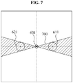
- FIG. 7 is a diagram illustrating a region identified according to a movement of an object in a proximity sensor according to an exemplary embodiment.
- the region 611 may have the predetermined size.
- the region 611 may be located on the right of the light source 501 with respect to the center of the image including the focus region.
- a surface area of the output light 601 may be reduced in a direction toward a focal distance. Therefore, as shown in a region change 700 of FIG. 7 , the size of the region 611 may be reduced as the object approximates the focus position.
- FIG. 7 shows the exemplary embodiment in which the light source 501 is located on the right of the proximity sensor 500, as shown in FIG. 6 .
- the region 611 may be moved from the upper portion to the center of the image as the object approximates the focus position.
- the region 611 may be moved from a direction of the light source 501 with respect to the proximity sensor 500 toward the center of the image.
- the region 621 may have the predetermined size.
- the surface area of the output light 601 may be increased in a direction away from the focus position as shown in FIG. 6 . Therefore, the size of the region 621 may be increased as the object is separated from the focus position, as shown in the region change 700 of FIG. 7 .
- FIG. 7 shows the exemplary embodiment in which the light source 501 is located on the right of the proximity sensor 500, as shown in FIG. 6 .
- the region 621 may be moved to a lower portion of the image as the object is separated from the focus position.
- the region 621 may be moved in a direction opposite to the light source 501.
- the region 631 may have the minimum size and may be located in the center of the image, corresponding to the focus region.
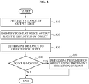
- FIG. 8 is a diagram illustrating a proximity sensing method of a proximity sensor according to an exemplary embodiment.
- the light source 101 may change the intensity of an output light according to at least one of a predetermine time interval, a particular condition, and a user operation.
- the pattern detection unit 110 may detect an event pattern of the reflected light.
- the image taking unit 120 may take the image including the object 102.
- the point ID unit 130 may identify the point at which the output light is reflected from the object 102 in the image taken in operation 810.
- the point ID unit 130 may distinguish the point and the noise generated from another light source in the image taken by the image taking unit 120 based on the event pattern of the reflected light detected in operation 810.
- the event pattern of the reflected light reflected at the point may correspond to the temporal change of the output light of the light source 101.
- the event pattern of the reflected light reflected at the noise is determined according to the change in the intensity of the output light output from the other light source or according to whether the output light output from the other light source is interrupted before reaching the object 102. Therefore, the event pattern may not correspond to the temporal change of the output light of the other light source. Therefore, the point ID unit 130 may identify at least one point at which the output light is reflected or the noise in the image taken by the image taking unit 120, and distinguish the point from the noise by comparing the event pattern of the identified point or the noise with the temporal change of the output light.
- the distance determination unit 140 may determine the distance between the object 102 and the proximity sensor 100 based on the position of the point identified in operation 820.
- the distance determination unit 140 may determine a direction corresponding to the position of the light source 101 on the image using the distance between the proximity sensor 100 and the light source 101, and determine the distance between the object 102 and the proximity sensor 100 using the distance between the position of the point and the side of the image corresponding to the identified direction.
- the distance determination unit 140 may determine whether the point is moved by comparing images successively taken by the image taking unit 120.
- the distance determination unit 140 may determine whether the object 102 approximates the proximity sensor 100 based on a movement direction of the point. In detail, when the movement direction of the point is the same as the direction of the light source 101 with respect to the proximity sensor 100, the distance determination unit 140 may determine that the object 102 approximates the proximity sensor 100. In addition, when the movement direction of the point is opposite to the direction of the light source 101 with respect to the proximity sensor 100, the distance determination unit 140 may determine that the object 102 is separated from the proximity sensor 100.
- FIG. 9 is a diagram illustrating a proximity sensing method of a proximity sensor according to another exemplary embodiment.
- the light source 501 may change the intensity of the output light according to at least one of a predetermine time interval, a particular condition, and a user operation.
- the pattern detection unit 510 may detect an event pattern of the reflected light.
- the image taking unit 520 may take the image including the object 502.
- the point ID unit 530 may identify the region at which the output light is reflected from the object 502 in the image taken in operation 910.
- the output light may be focused to the focus point by the lens of the light source 501. That is, as the object 502 is nearer to the focus position, the output light reflected from the object 502 may be focused and reduced in area. Accordingly, as the object 502 is nearer to the focus position, the size of the region identified by the region ID unit 530 may be reduced.
- the region ID unit 530 may distinguish the region and the noise generated by another light source in the image taken by the image taking unit 520.
- the event pattern of the reflected light reflected at the region may correspond to a temporal change of the output light of the light source 501.
- the event pattern of the reflected light reflected at the noise is determined according to the change in the intensity of the output light output from the other light source or according to whether the output light output from the other light source is interrupted before reaching the object 502. Therefore, the event pattern may not correspond to the temporal change of the output light of the other light source.
- the region ID unit 530 may identify at least one region at which the output light is reflected or the noise in the image taken by the image taking unit 520, and distinguish the region from the noise by comparing the event pattern of the identified point or the noise with the temporal change of the output light.
- the distance determination unit 540 may determine the distance between the object 502 and the proximity sensor 500 based on the position and the size of the region identified in operation 920.
- the distance determination unit 540 may identify a direction corresponding to the position of the light source 501 on the image using the distance between the proximity sensor 500 and the light source 501, and determine the distance between the object 502 and the proximity sensor 500 using the distance between the position of the region and the side of the image corresponding to the identified direction.
- the distance determination unit 540 may determine the distance between the object 502 and the proximity sensor 500 using the size of the region. As the object 502 is nearer to the focus position, the size of the region identified by the region ID unit 530 may be reduced. Therefore, when the size of the region identified by the region ID unit 530 is minimized, the distance determination unit 540 may determine that the object 502 is located on the focus position.
- the distance determination unit 540 may check whether the region is moved by comparing the images successively taken by the image taking unit 520.
- the distance determination unit 540 may determine whether the object 502 approximates the proximity sensor 500 based on a movement direction of the point. In detail, when the movement direction of the point is the same as the direction of the light source 501 with respect to the proximity sensor 500, the distance determination unit 540 may determine that the object 502 approximates the proximity sensor 500. In addition, when the movement direction of the point is opposite to the direction of the light source 501 with respect to the proximity sensor 500, the distance determination unit 540 may determine that the object 502 is separated from the proximity sensor 500.
- non-transitory computer-readable media may be recorded in non-transitory computer-readable media as program instructions to implement various operations embodied by a computer that includes a processor executing the program instructions.
- the media may also include, alone or in combination with the program instructions, data files, data structures, and the like.
- Examples of non-transitory computer-readable media include magnetic media such as hard disks, floppy disks, and magnetic tape; optical media such as CD ROM disks and DVDs; magneto-optical media such as optical disks; and hardware devices that are specially configured to store and perform program instructions, such as read-only memory (ROM), random access memory (RAM), flash memory, and the like.
- Examples of program instructions include both machine code, such as produced by a compiler, and files containing higher level code that may be executed by the computer using an interpreter.
- the described hardware devices may be configured to act as one or more software modules in order to perform the operations of the above-described exemplary embodiments, or vice versa.
Landscapes
- Physics & Mathematics (AREA)
- Engineering & Computer Science (AREA)
- Electromagnetism (AREA)
- Computer Networks & Wireless Communication (AREA)
- General Physics & Mathematics (AREA)
- Radar, Positioning & Navigation (AREA)
- Remote Sensing (AREA)
- Measurement Of Optical Distance (AREA)
- Length Measuring Devices By Optical Means (AREA)
- Geophysics And Detection Of Objects (AREA)
- Optical Radar Systems And Details Thereof (AREA)
Claims (14)
- Capteur de proximité (100) consistant en un capteur visuel événementiel comprenant :une unité d'identification de point (130) conçue pour identifier un point, dans une image, auquel de la lumière émise par une source de lumière dirigée (101) est réfléchie par un objet (102), etune unité de détermination de distance (140) conçue pour déterminer la distance séparant l'objet du capteur de proximité compte tenu de la position du point dans l'image ;CARACTÉRISÉ PARune unité de détection de schéma (110) conçue pour détecter un schéma événementiel d'une lumière réfléchie par l'objet (102), le schéma événementiel correspondant à un schéma dans lequel l'intensité de la lumière émise est modifiée ;ladite unité d'identification de point (130) étant conçue pour identifier le point dans l'image compte tenu du schéma événementiel de la lumière réfléchie et pour différencier ledit point d'un bruit généré par une autre source de lumière compte tenu d'une comparaison entre le schéma événementiel et une modification temporelle de la lumière émise par la source de lumière dirigée (101),le nombre d'événements correspondant à la modification temporelle de la lumière émise parmi les événements du schéma événementiel étant inversement proportionnel à la distance séparant l'objet (102) du capteur de proximité (100), etladite unité de détermination de distance (140) étant conçue pour déterminer la proximité de l'objet (102) d'après le nombre d'événements correspondant à la modification temporelle de la lumière émise parmi les événements du schéma événementiel.
- Capteur de proximité (500) consistant en un capteur visuel événementiel comprenant :une unité d'identification de région (530) conçue pour identifier une région, dans une image, dans laquelle de la lumière émise par une source de lumière diffuse (501) est réfléchie par un objet (502), etune unité de détermination de distance (540) conçue pour déterminer la distance séparant l'objet (502) du capteur de proximité (100) compte tenu de la position de la région dans l'image ;CARACTÉRISÉ PARune unité de détection de schéma (510) conçue pour détecter un schéma événementiel d'une lumière réfléchie par l'objet (502), le schéma événementiel correspondant à un schéma dans lequel l'intensité de la lumière émise est modifiée ;ladite unité d'identification de région (530) étant conçue pour identifier la région dans l'image compte tenu du schéma événementiel de la lumière réfléchie et pour différencier ladite région d'un bruit généré par une autre source de lumière compte tenu d'une comparaison entre le schéma événementiel et une modification temporelle de la lumière émise par la source de lumière diffuse (501),le nombre d'événements correspondant à la modification temporelle de la lumière émise parmi les événements du schéma événementiel étant inversement proportionnel à la distance séparant l'objet (502) du capteur de proximité (500), etladite unité de détermination de distance (540) étant conçue pour déterminer la proximité de l'objet (502) d'après le nombre d'événements correspondant à la modification temporelle de la lumière émise parmi les événements du schéma événementiel.
- Capteur de proximité selon la revendication 2, comprenant en outre :
une lentille (611, 621) conçue pour focaliser la lumière émise par la source de lumière diffuse (501) vers une position de focalisation séparée du capteur de proximité (500) selon une distance prédéterminée. - Capteur de proximité selon la revendication 2, dans lequel l'unité de détermination de distance (540) est conçue pour déterminer la distance séparant l'objet (502) du capteur de proximité (500) d'après la taille de la région et la position de la focalisation de la source de lumière diffuse (501).
- Capteur de proximité selon l'une au moins des revendications précédentes, dans lequel l'unité de détermination de distance (140 ; 540) est conçue pour déterminer la distance séparant l'objet (102 ; 502) du capteur de proximité d'après l'angle selon lequel la lumière est émise vers l'objet (102 ; 502), la distance séparant le capteur de proximité (100 ; 500) de la source de lumière dirigée (101) ou de la source de lumière diffuse (501), et la position du point ou de la région dans l'image.
- Capteur de proximité selon l'une au moins des revendications précédentes, dans lequel l'unité de détermination de distance (140 ; 540) est conçue pour déterminer la distance séparant l'objet (102 ; 502) du capteur de proximité (100 ; 500) comme étant proportionnelle à la distance séparant un bord latéral de l'image, correspondant à la source de lumière dirigée (100) ou à la source de lumière diffuse (501), de la position du point ou de la région dans l'image.
- Capteur de proximité selon l'une au moins des revendications précédentes, dans lequel l'unité de détermination de distance (140 ; 540) est conçue pour déterminer la distance séparant l'objet (102 ; 502) du capteur de proximité (100 ; 500) comme étant proportionnelle à la taille de l'image et à la distance séparant le capteur de proximité (100 ; 500) de la source de lumière dirigée (102) ou de la source de lumière diffuse (502).
- Capteur de proximité selon l'une au moins des revendications précédentes, dans lequel l'unité de détermination de distance (140 ; 540) est conçue pour déterminer si l'objet (102 ; 502) s'approche du capteur de proximité (100 ; 500) compte tenu d'une direction de déplacement du point ou de la région dans l'image.
- Procédé de détermination de la distance séparant un objet d'un capteur de proximité selon la revendication 1, le procédé comprenant :l'identification d'un point, dans une image, auquel de la lumière émise par une source de lumière dirigée est réfléchie par l'objet, etla détermination de la distance séparant l'objet du capteur de proximité compte tenu de la position du point dans l'image ;CARACTÉRISÉ PARla détection d'un schéma événementiel d'une lumière réfléchie par l'objet, le schéma événementiel correspondant à un schéma dans lequel l'intensité de la lumière émise est modifiée,l'identification du point dans l'image compte tenu du schéma événementiel de la lumière réfléchie, la différenciation entre ledit point et un bruit généré par une autre source de lumière, compte tenu d'une comparaison entre le schéma événementiel et une modification temporelle de la lumière émise par la source de lumière dirigée, etla détermination de la proximité de l'objet d'après le nombre d'événements correspondant à la modification temporelle de la lumière émise parmi les événements du schéma événementiel ;ledit nombre d'événements correspondant à la modification temporelle de la lumière émise parmi les événements du schéma événementiel étant inversement proportionnel à la distance séparant l'objet du capteur de proximité.
- Procédé de détermination de la distance séparant un objet d'un capteur de proximité selon la revendication 2, le procédé comprenant :l'identification d'une région, dans une image, dans laquelle de la lumière émise par une source de lumière diffuse est réfléchie par un objet, etla détermination de la distance séparant l'objet du capteur de proximité compte tenu de la position de la région dans l'image ;CARACTÉRISÉ PARla détection d'un schéma événementiel d'une lumière réfléchie par l'objet, le schéma événementiel correspondant à un schéma dans lequel l'intensité de la lumière émise est modifiée,l'identification de la région dans l'image compte tenu du schéma événementiel de la lumière réfléchie,la différenciation entre ladite région et un bruit généré par une autre source de lumière compte tenu d'une comparaison entre le schéma événementiel et une modification temporelle de la lumière émise par la source de lumière diffuse, etla détermination de la proximité de l'objet d'après le nombre d'événements correspondant à la modification temporelle de la lumière émise parmi les événements du schéma événementiel ;ledit nombre d'événements correspondant à la modification temporelle de la lumière émise parmi les événements du schéma événementiel étant inversement proportionnel à la distance séparant l'objet du capteur de proximité.
- Procédé selon la revendication 10, comprenant en outre :
la focalisation de la lumière émise vers une position de focalisation séparée du capteur de proximité selon une distance prédéterminée. - Procédé selon la revendication 10, dans lequel la détermination de la distance comprend la détermination de la distance séparant l'objet du capteur de proximité d'après la taille de la région et la position de la focalisation de la source de lumière diffuse.
- Procédé selon l'une au moins des revendications précédentes 9 à 12, dans lequel la détermination de la distance comprend la détermination de la distance séparant l'objet du capteur de proximité, d'après l'angle selon lequel la lumière est émise vers l'objet, la distance séparant le capteur de proximité de la source de lumière dirigée ou de la source de lumière diffuse, et la position du point ou de la région dans l'image.
- Support d'enregistrement non transitoire lisible par ordinateur, sur lequel est enregistré un programme visant à amener un capteur de proximité selon la revendication 1 ou 2 à exécuter le procédé selon l'une au moins des revendications 9 et 13 ou des revendications 10 à 13, respectivement.
Applications Claiming Priority (2)
| Application Number | Priority Date | Filing Date | Title |
|---|---|---|---|
| KR1020120107431A KR102074857B1 (ko) | 2012-09-26 | 2012-09-26 | 이벤트 기반 비전 센서를 이용한 근접 센서 및 근접 센싱 방법 |
| PCT/KR2013/008642 WO2014051362A1 (fr) | 2012-09-26 | 2013-09-26 | Capteur de proximité et procédé de détection de proximité utilisant un capteur de vision fondé sur des évènements |
Publications (3)
| Publication Number | Publication Date |
|---|---|
| EP2902803A1 EP2902803A1 (fr) | 2015-08-05 |
| EP2902803A4 EP2902803A4 (fr) | 2016-04-27 |
| EP2902803B1 true EP2902803B1 (fr) | 2020-09-16 |
Family
ID=50338531
Family Applications (1)
| Application Number | Title | Priority Date | Filing Date |
|---|---|---|---|
| EP13842660.6A Active EP2902803B1 (fr) | 2012-09-26 | 2013-09-26 | Capteur de proximité et procédé de détection de proximité utilisant un capteur de vision fondé sur des évènements |
Country Status (4)
| Country | Link |
|---|---|
| US (1) | US9921310B2 (fr) |
| EP (1) | EP2902803B1 (fr) |
| KR (1) | KR102074857B1 (fr) |
| WO (1) | WO2014051362A1 (fr) |
Families Citing this family (10)
| Publication number | Priority date | Publication date | Assignee | Title |
|---|---|---|---|---|
| KR101620427B1 (ko) * | 2014-10-14 | 2016-05-12 | 엘지전자 주식회사 | 로봇 청소기의 제어방법 |
| CN106991650B (zh) * | 2016-01-21 | 2020-09-15 | 北京三星通信技术研究有限公司 | 一种图像去模糊的方法和装置 |
| KR102720734B1 (ko) | 2016-08-02 | 2024-10-22 | 삼성전자주식회사 | 이벤트 신호 처리 방법 및 장치 |
| US10807309B2 (en) * | 2017-11-17 | 2020-10-20 | 3D Systems, Inc. | Latching system for three dimensional print engine |
| WO2020261370A1 (fr) * | 2019-06-25 | 2020-12-30 | 株式会社ソニー・インタラクティブエンタテインメント | Système, dispositif ainsi que procédé de détection de position, et programme |
| CN112689082B (zh) * | 2019-10-17 | 2022-05-17 | 电装波动株式会社 | 具备事件相机的摄像装置 |
| KR102334167B1 (ko) * | 2020-03-23 | 2021-12-03 | 한국과학기술원 | ToF 기반 3D 카메라를 이용하여 거리 해상도를 향상하는 장치 및 방법 |
| JP2022121991A (ja) | 2021-02-09 | 2022-08-22 | ソニーセミコンダクタソリューションズ株式会社 | センシングシステム、信号処理装置 |
| JP2023113553A (ja) * | 2022-02-03 | 2023-08-16 | オプテックス株式会社 | 距離測定装置、自動ドアシステム、開閉システムおよび距離測定方法 |
| WO2023181308A1 (fr) * | 2022-03-24 | 2023-09-28 | 株式会社ソニー・インタラクティブエンタテインメント | Système, procédé et programme informatique |
Family Cites Families (27)
| Publication number | Priority date | Publication date | Assignee | Title |
|---|---|---|---|---|
| KR0168087B1 (ko) * | 1993-06-29 | 1999-05-01 | 김광호 | 초음파센서를 이용한 장애물의 거리 측정장치 그 방법 |
| KR20020066847A (ko) * | 2001-02-14 | 2002-08-21 | 현대중공업 주식회사 | 시각센서를 이용한 V, U, Butt, 필릿 및 랩 조인트형상인식 방법 |
| JP2003172780A (ja) | 2001-12-06 | 2003-06-20 | Daihatsu Motor Co Ltd | 前方車両の認識装置及び認識方法 |
| KR100556612B1 (ko) | 2002-06-29 | 2006-03-06 | 삼성전자주식회사 | 레이저를 이용한 위치 측정 장치 및 방법 |
| GB2395261A (en) * | 2002-11-11 | 2004-05-19 | Qinetiq Ltd | Ranging apparatus |
| KR20060074503A (ko) | 2004-12-27 | 2006-07-03 | 동부일렉트로닉스 주식회사 | 근접 센서 |
| US8150574B2 (en) * | 2005-01-04 | 2012-04-03 | Deere & Company | Method and system for guiding a vehicle with vision-based adjustment |
| JP5244587B2 (ja) | 2005-06-03 | 2013-07-24 | ウニヴェルズィテート チューリッヒ | 時間依存性の画像データを検出するフォトアレイ |
| US7929798B2 (en) * | 2005-12-07 | 2011-04-19 | Micron Technology, Inc. | Method and apparatus providing noise reduction while preserving edges for imagers |
| US20070133893A1 (en) * | 2005-12-14 | 2007-06-14 | Micron Technology, Inc. | Method and apparatus for image noise reduction |
| KR100769461B1 (ko) * | 2005-12-14 | 2007-10-23 | 이길재 | 스테레오 비전 시스템 |
| KR100809317B1 (ko) | 2006-07-28 | 2008-03-05 | 두얼메카닉스 주식회사 | 위치 검출 방법 및 그 방법을 이용한 이동 장치 |
| KR100825919B1 (ko) * | 2006-12-18 | 2008-04-28 | 엘지전자 주식회사 | 거리 측정 센서, 거리 측정 센서를 가진 이동로봇 및 그를이용한 이동로봇 주행 방법 |
| US7778484B2 (en) * | 2007-01-05 | 2010-08-17 | Seiko Epson Corporation | Method and apparatus for reducing noise in an image using wavelet decomposition |
| KR100823870B1 (ko) | 2007-10-04 | 2008-04-21 | 주식회사 자티전자 | 근접 센서를 이용한 휴대용 단말기의 자동 절전 시스템 및그 방법 |
| US7907061B2 (en) | 2007-11-14 | 2011-03-15 | Intersil Americas Inc. | Proximity sensors and methods for sensing proximity |
| KR101412751B1 (ko) * | 2008-03-14 | 2014-08-06 | 엘지전자 주식회사 | 이동로봇 및 그 동작방법 |
| KR101501949B1 (ko) | 2008-04-04 | 2015-03-11 | 엘지전자 주식회사 | 근접센서를 이용하여 동작 제어가 가능한 휴대 단말기 및그 제어방법 |
| KR101516361B1 (ko) | 2008-05-26 | 2015-05-04 | 엘지전자 주식회사 | 근접센서를 이용하는 휴대 단말기 및 그 제어방법 |
| KR20100067723A (ko) * | 2008-12-12 | 2010-06-22 | 엘지전자 주식회사 | 기록매체의 기록재생방법 및 기록재생장치 |
| KR101137411B1 (ko) | 2009-09-14 | 2012-04-20 | 마루엘에스아이 주식회사 | 근접센서 |
| KR101628081B1 (ko) * | 2009-11-05 | 2016-06-22 | 삼성전자주식회사 | 영상 센서 기반의 다중 터치 인식 장치 및 방법 |
| US8854471B2 (en) | 2009-11-13 | 2014-10-07 | Korea Institute Of Science And Technology | Infrared sensor and sensing method using the same |
| JP5263193B2 (ja) | 2010-02-04 | 2013-08-14 | オムロン株式会社 | 近接センサ |
| JP5491247B2 (ja) | 2010-03-25 | 2014-05-14 | セイコーインスツル株式会社 | 光センサを用いた近接センサ |
| JP5160625B2 (ja) | 2010-12-02 | 2013-03-13 | シャープ株式会社 | 近接センサ及び電子機器 |
| KR101292055B1 (ko) * | 2011-02-14 | 2013-08-01 | 조수호 | 감지영역 설정 시스템 및 방법 |
-
2012
- 2012-09-26 KR KR1020120107431A patent/KR102074857B1/ko active Active
-
2013
- 2013-09-26 EP EP13842660.6A patent/EP2902803B1/fr active Active
- 2013-09-26 WO PCT/KR2013/008642 patent/WO2014051362A1/fr not_active Ceased
- 2013-09-26 US US14/037,950 patent/US9921310B2/en active Active
Non-Patent Citations (1)
| Title |
|---|
| None * |
Also Published As
| Publication number | Publication date |
|---|---|
| US9921310B2 (en) | 2018-03-20 |
| EP2902803A1 (fr) | 2015-08-05 |
| US20140085621A1 (en) | 2014-03-27 |
| WO2014051362A1 (fr) | 2014-04-03 |
| KR102074857B1 (ko) | 2020-02-10 |
| KR20140042016A (ko) | 2014-04-07 |
| EP2902803A4 (fr) | 2016-04-27 |
Similar Documents
| Publication | Publication Date | Title |
|---|---|---|
| EP2902803A1 (fr) | Capteur de proximité et procédé de détection de proximité utilisant un capteur de vision fondé sur des évènements | |
| US8194927B2 (en) | Road-lane marker detection using light-based sensing technology | |
| KR101436786B1 (ko) | 위조 지문 판별 장치 및 방법 | |
| US8099213B2 (en) | Road-edge detection | |
| US9243904B2 (en) | Proximity sensor and proximity sensing method using light quantity of reflection light | |
| US20180025196A1 (en) | Depth sensor based auto-focus system for an indicia scanner | |
| US8131027B2 (en) | Finger contact detecting apparatus, finger contact detecting method, fingerprint reading apparatus and computer-readable recording medium | |
| US20200319309A1 (en) | Illumination device, time of flight system and method | |
| CN105261108B (zh) | 一种人民币币值识别的方法和系统 | |
| EP2688278A1 (fr) | Dispositif d'imagerie, procédé d'imagerie et programme d'imagerie | |
| JP4868597B2 (ja) | エッジ検出装置 | |
| US20190293419A1 (en) | Distance detection device | |
| TWI674002B (zh) | 安全監控系統的運作方式 | |
| US20080204761A1 (en) | Pointing device | |
| KR102081778B1 (ko) | 객체의 3차원 형상을 산출하는 장치 및 방법 | |
| JP6472670B2 (ja) | 一次元輝度分布検知装置 | |
| US11287901B2 (en) | Optical detecting device with lift height detection function | |
| US20150042761A1 (en) | Method, apparatus, and stereo camera for controlling image lightness | |
| JP2014025804A (ja) | 情報取得装置および物体検出装置 | |
| US11453259B2 (en) | Object surface managing method and object surface managing system | |
| US11480664B2 (en) | Optical detection device of detecting a distance relative to a target object | |
| JP2007064733A (ja) | エッジ検出装置 | |
| CN107483659A (zh) | 基于接近传感器的控制方法、装置和移动终端 | |
| US20220207753A1 (en) | Counting method, counting device, and recording medium | |
| JP2002324259A (ja) | 硬貨識別方法および装置 |
Legal Events
| Date | Code | Title | Description |
|---|---|---|---|
| PUAI | Public reference made under article 153(3) epc to a published international application that has entered the european phase |
Free format text: ORIGINAL CODE: 0009012 |
|
| 17P | Request for examination filed |
Effective date: 20140722 |
|
| AK | Designated contracting states |
Kind code of ref document: A1 Designated state(s): AL AT BE BG CH CY CZ DE DK EE ES FI FR GB GR HR HU IE IS IT LI LT LU LV MC MK MT NL NO PL PT RO RS SE SI SK SM TR |
|
| AX | Request for extension of the european patent |
Extension state: BA ME |
|
| DAX | Request for extension of the european patent (deleted) | ||
| REG | Reference to a national code |
Ref country code: DE Ref legal event code: R079 Ref document number: 602013072638 Country of ref document: DE Free format text: PREVIOUS MAIN CLASS: G01S0017080000 Ipc: G01S0017460000 |
|
| RA4 | Supplementary search report drawn up and despatched (corrected) |
Effective date: 20160329 |
|
| RIC1 | Information provided on ipc code assigned before grant |
Ipc: G01S 7/493 20060101ALI20160321BHEP Ipc: G01S 7/481 20060101ALI20160321BHEP Ipc: G01S 17/46 20060101AFI20160321BHEP Ipc: G01S 17/50 20060101ALI20160321BHEP |
|
| STAA | Information on the status of an ep patent application or granted ep patent |
Free format text: STATUS: EXAMINATION IS IN PROGRESS |
|
| 17Q | First examination report despatched |
Effective date: 20180328 |
|
| GRAP | Despatch of communication of intention to grant a patent |
Free format text: ORIGINAL CODE: EPIDOSNIGR1 |
|
| STAA | Information on the status of an ep patent application or granted ep patent |
Free format text: STATUS: GRANT OF PATENT IS INTENDED |
|
| INTG | Intention to grant announced |
Effective date: 20200603 |
|
| GRAS | Grant fee paid |
Free format text: ORIGINAL CODE: EPIDOSNIGR3 |
|
| GRAA | (expected) grant |
Free format text: ORIGINAL CODE: 0009210 |
|
| STAA | Information on the status of an ep patent application or granted ep patent |
Free format text: STATUS: THE PATENT HAS BEEN GRANTED |
|
| AK | Designated contracting states |
Kind code of ref document: B1 Designated state(s): AL AT BE BG CH CY CZ DE DK EE ES FI FR GB GR HR HU IE IS IT LI LT LU LV MC MK MT NL NO PL PT RO RS SE SI SK SM TR |
|
| REG | Reference to a national code |
Ref country code: GB Ref legal event code: FG4D |
|
| REG | Reference to a national code |
Ref country code: CH Ref legal event code: EP |
|
| REG | Reference to a national code |
Ref country code: DE Ref legal event code: R096 Ref document number: 602013072638 Country of ref document: DE |
|
| REG | Reference to a national code |
Ref country code: IE Ref legal event code: FG4D |
|
| REG | Reference to a national code |
Ref country code: AT Ref legal event code: REF Ref document number: 1314650 Country of ref document: AT Kind code of ref document: T Effective date: 20201015 |
|
| PG25 | Lapsed in a contracting state [announced via postgrant information from national office to epo] |
Ref country code: GR Free format text: LAPSE BECAUSE OF FAILURE TO SUBMIT A TRANSLATION OF THE DESCRIPTION OR TO PAY THE FEE WITHIN THE PRESCRIBED TIME-LIMIT Effective date: 20201217 Ref country code: NO Free format text: LAPSE BECAUSE OF FAILURE TO SUBMIT A TRANSLATION OF THE DESCRIPTION OR TO PAY THE FEE WITHIN THE PRESCRIBED TIME-LIMIT Effective date: 20201216 Ref country code: SE Free format text: LAPSE BECAUSE OF FAILURE TO SUBMIT A TRANSLATION OF THE DESCRIPTION OR TO PAY THE FEE WITHIN THE PRESCRIBED TIME-LIMIT Effective date: 20200916 Ref country code: FI Free format text: LAPSE BECAUSE OF FAILURE TO SUBMIT A TRANSLATION OF THE DESCRIPTION OR TO PAY THE FEE WITHIN THE PRESCRIBED TIME-LIMIT Effective date: 20200916 Ref country code: HR Free format text: LAPSE BECAUSE OF FAILURE TO SUBMIT A TRANSLATION OF THE DESCRIPTION OR TO PAY THE FEE WITHIN THE PRESCRIBED TIME-LIMIT Effective date: 20200916 Ref country code: BG Free format text: LAPSE BECAUSE OF FAILURE TO SUBMIT A TRANSLATION OF THE DESCRIPTION OR TO PAY THE FEE WITHIN THE PRESCRIBED TIME-LIMIT Effective date: 20201216 |
|
| REG | Reference to a national code |
Ref country code: AT Ref legal event code: MK05 Ref document number: 1314650 Country of ref document: AT Kind code of ref document: T Effective date: 20200916 |
|
| REG | Reference to a national code |
Ref country code: NL Ref legal event code: MP Effective date: 20200916 |
|
| PG25 | Lapsed in a contracting state [announced via postgrant information from national office to epo] |
Ref country code: LV Free format text: LAPSE BECAUSE OF FAILURE TO SUBMIT A TRANSLATION OF THE DESCRIPTION OR TO PAY THE FEE WITHIN THE PRESCRIBED TIME-LIMIT Effective date: 20200916 Ref country code: RS Free format text: LAPSE BECAUSE OF FAILURE TO SUBMIT A TRANSLATION OF THE DESCRIPTION OR TO PAY THE FEE WITHIN THE PRESCRIBED TIME-LIMIT Effective date: 20200916 |
|
| REG | Reference to a national code |
Ref country code: LT Ref legal event code: MG4D |
|
| PG25 | Lapsed in a contracting state [announced via postgrant information from national office to epo] |
Ref country code: PT Free format text: LAPSE BECAUSE OF FAILURE TO SUBMIT A TRANSLATION OF THE DESCRIPTION OR TO PAY THE FEE WITHIN THE PRESCRIBED TIME-LIMIT Effective date: 20210118 Ref country code: LT Free format text: LAPSE BECAUSE OF FAILURE TO SUBMIT A TRANSLATION OF THE DESCRIPTION OR TO PAY THE FEE WITHIN THE PRESCRIBED TIME-LIMIT Effective date: 20200916 Ref country code: NL Free format text: LAPSE BECAUSE OF FAILURE TO SUBMIT A TRANSLATION OF THE DESCRIPTION OR TO PAY THE FEE WITHIN THE PRESCRIBED TIME-LIMIT Effective date: 20200916 Ref country code: RO Free format text: LAPSE BECAUSE OF FAILURE TO SUBMIT A TRANSLATION OF THE DESCRIPTION OR TO PAY THE FEE WITHIN THE PRESCRIBED TIME-LIMIT Effective date: 20200916 Ref country code: SM Free format text: LAPSE BECAUSE OF FAILURE TO SUBMIT A TRANSLATION OF THE DESCRIPTION OR TO PAY THE FEE WITHIN THE PRESCRIBED TIME-LIMIT Effective date: 20200916 Ref country code: CZ Free format text: LAPSE BECAUSE OF FAILURE TO SUBMIT A TRANSLATION OF THE DESCRIPTION OR TO PAY THE FEE WITHIN THE PRESCRIBED TIME-LIMIT Effective date: 20200916 Ref country code: EE Free format text: LAPSE BECAUSE OF FAILURE TO SUBMIT A TRANSLATION OF THE DESCRIPTION OR TO PAY THE FEE WITHIN THE PRESCRIBED TIME-LIMIT Effective date: 20200916 |
|
| REG | Reference to a national code |
Ref country code: CH Ref legal event code: PL |
|
| PG25 | Lapsed in a contracting state [announced via postgrant information from national office to epo] |
Ref country code: ES Free format text: LAPSE BECAUSE OF FAILURE TO SUBMIT A TRANSLATION OF THE DESCRIPTION OR TO PAY THE FEE WITHIN THE PRESCRIBED TIME-LIMIT Effective date: 20200916 Ref country code: AT Free format text: LAPSE BECAUSE OF FAILURE TO SUBMIT A TRANSLATION OF THE DESCRIPTION OR TO PAY THE FEE WITHIN THE PRESCRIBED TIME-LIMIT Effective date: 20200916 Ref country code: AL Free format text: LAPSE BECAUSE OF FAILURE TO SUBMIT A TRANSLATION OF THE DESCRIPTION OR TO PAY THE FEE WITHIN THE PRESCRIBED TIME-LIMIT Effective date: 20200916 Ref country code: IS Free format text: LAPSE BECAUSE OF FAILURE TO SUBMIT A TRANSLATION OF THE DESCRIPTION OR TO PAY THE FEE WITHIN THE PRESCRIBED TIME-LIMIT Effective date: 20210116 Ref country code: PL Free format text: LAPSE BECAUSE OF FAILURE TO SUBMIT A TRANSLATION OF THE DESCRIPTION OR TO PAY THE FEE WITHIN THE PRESCRIBED TIME-LIMIT Effective date: 20200916 |
|
| REG | Reference to a national code |
Ref country code: DE Ref legal event code: R097 Ref document number: 602013072638 Country of ref document: DE |
|
| REG | Reference to a national code |
Ref country code: BE Ref legal event code: MM Effective date: 20200930 |
|
| PG25 | Lapsed in a contracting state [announced via postgrant information from national office to epo] |
Ref country code: LU Free format text: LAPSE BECAUSE OF NON-PAYMENT OF DUE FEES Effective date: 20200926 Ref country code: SK Free format text: LAPSE BECAUSE OF FAILURE TO SUBMIT A TRANSLATION OF THE DESCRIPTION OR TO PAY THE FEE WITHIN THE PRESCRIBED TIME-LIMIT Effective date: 20200916 Ref country code: MC Free format text: LAPSE BECAUSE OF FAILURE TO SUBMIT A TRANSLATION OF THE DESCRIPTION OR TO PAY THE FEE WITHIN THE PRESCRIBED TIME-LIMIT Effective date: 20200916 |
|
| PLBE | No opposition filed within time limit |
Free format text: ORIGINAL CODE: 0009261 |
|
| STAA | Information on the status of an ep patent application or granted ep patent |
Free format text: STATUS: NO OPPOSITION FILED WITHIN TIME LIMIT |
|
| 26N | No opposition filed |
Effective date: 20210617 |
|
| GBPC | Gb: european patent ceased through non-payment of renewal fee |
Effective date: 20201216 |
|
| PG25 | Lapsed in a contracting state [announced via postgrant information from national office to epo] |
Ref country code: LI Free format text: LAPSE BECAUSE OF NON-PAYMENT OF DUE FEES Effective date: 20200930 Ref country code: IE Free format text: LAPSE BECAUSE OF NON-PAYMENT OF DUE FEES Effective date: 20200926 Ref country code: SI Free format text: LAPSE BECAUSE OF FAILURE TO SUBMIT A TRANSLATION OF THE DESCRIPTION OR TO PAY THE FEE WITHIN THE PRESCRIBED TIME-LIMIT Effective date: 20200916 Ref country code: DK Free format text: LAPSE BECAUSE OF FAILURE TO SUBMIT A TRANSLATION OF THE DESCRIPTION OR TO PAY THE FEE WITHIN THE PRESCRIBED TIME-LIMIT Effective date: 20200916 Ref country code: CH Free format text: LAPSE BECAUSE OF NON-PAYMENT OF DUE FEES Effective date: 20200930 Ref country code: BE Free format text: LAPSE BECAUSE OF NON-PAYMENT OF DUE FEES Effective date: 20200930 |
|
| PG25 | Lapsed in a contracting state [announced via postgrant information from national office to epo] |
Ref country code: FR Free format text: LAPSE BECAUSE OF NON-PAYMENT OF DUE FEES Effective date: 20201116 Ref country code: IT Free format text: LAPSE BECAUSE OF FAILURE TO SUBMIT A TRANSLATION OF THE DESCRIPTION OR TO PAY THE FEE WITHIN THE PRESCRIBED TIME-LIMIT Effective date: 20200916 |
|
| PG25 | Lapsed in a contracting state [announced via postgrant information from national office to epo] |
Ref country code: GB Free format text: LAPSE BECAUSE OF NON-PAYMENT OF DUE FEES Effective date: 20201216 |
|
| PG25 | Lapsed in a contracting state [announced via postgrant information from national office to epo] |
Ref country code: IS Free format text: LAPSE BECAUSE OF FAILURE TO SUBMIT A TRANSLATION OF THE DESCRIPTION OR TO PAY THE FEE WITHIN THE PRESCRIBED TIME-LIMIT Effective date: 20210116 Ref country code: TR Free format text: LAPSE BECAUSE OF FAILURE TO SUBMIT A TRANSLATION OF THE DESCRIPTION OR TO PAY THE FEE WITHIN THE PRESCRIBED TIME-LIMIT Effective date: 20200916 Ref country code: MT Free format text: LAPSE BECAUSE OF FAILURE TO SUBMIT A TRANSLATION OF THE DESCRIPTION OR TO PAY THE FEE WITHIN THE PRESCRIBED TIME-LIMIT Effective date: 20200916 Ref country code: CY Free format text: LAPSE BECAUSE OF FAILURE TO SUBMIT A TRANSLATION OF THE DESCRIPTION OR TO PAY THE FEE WITHIN THE PRESCRIBED TIME-LIMIT Effective date: 20200916 |
|
| PG25 | Lapsed in a contracting state [announced via postgrant information from national office to epo] |
Ref country code: MK Free format text: LAPSE BECAUSE OF FAILURE TO SUBMIT A TRANSLATION OF THE DESCRIPTION OR TO PAY THE FEE WITHIN THE PRESCRIBED TIME-LIMIT Effective date: 20200916 |
|
| P01 | Opt-out of the competence of the unified patent court (upc) registered |
Effective date: 20230520 |
|
| PGFP | Annual fee paid to national office [announced via postgrant information from national office to epo] |
Ref country code: DE Payment date: 20250730 Year of fee payment: 13 |