EP2902931A1 - Gruppenantenne und basisstation - Google Patents
Gruppenantenne und basisstation Download PDFInfo
- Publication number
- EP2902931A1 EP2902931A1 EP12885274.6A EP12885274A EP2902931A1 EP 2902931 A1 EP2902931 A1 EP 2902931A1 EP 12885274 A EP12885274 A EP 12885274A EP 2902931 A1 EP2902931 A1 EP 2902931A1
- Authority
- EP
- European Patent Office
- Prior art keywords
- downlink
- uplink
- array
- linear arrays
- array antenna
- Prior art date
- Legal status (The legal status is an assumption and is not a legal conclusion. Google has not performed a legal analysis and makes no representation as to the accuracy of the status listed.)
- Granted
Links
Images


Classifications
-
- H—ELECTRICITY
- H01—ELECTRIC ELEMENTS
- H01Q—ANTENNAS, i.e. RADIO AERIALS
- H01Q21/00—Antenna arrays or systems
- H01Q21/06—Arrays of individually energised antenna units similarly polarised and spaced apart
- H01Q21/061—Two dimensional planar arrays
-
- H—ELECTRICITY
- H01—ELECTRIC ELEMENTS
- H01Q—ANTENNAS, i.e. RADIO AERIALS
- H01Q1/00—Details of, or arrangements associated with, antennas
- H01Q1/12—Supports; Mounting means
- H01Q1/22—Supports; Mounting means by structural association with other equipment or articles
- H01Q1/24—Supports; Mounting means by structural association with other equipment or articles with receiving set
- H01Q1/241—Supports; Mounting means by structural association with other equipment or articles with receiving set used in mobile communications, e.g. GSM
- H01Q1/246—Supports; Mounting means by structural association with other equipment or articles with receiving set used in mobile communications, e.g. GSM specially adapted for base stations
-
- H—ELECTRICITY
- H01—ELECTRIC ELEMENTS
- H01Q—ANTENNAS, i.e. RADIO AERIALS
- H01Q21/00—Antenna arrays or systems
- H01Q21/24—Combinations of antenna units polarised in different directions for transmitting or receiving circularly and elliptically polarised waves or waves linearly polarised in any direction
- H01Q21/26—Turnstile or like antennas comprising arrangements of three or more elongated elements disposed radially and symmetrically in a horizontal plane about a common centre
-
- H—ELECTRICITY
- H04—ELECTRIC COMMUNICATION TECHNIQUE
- H04B—TRANSMISSION
- H04B7/00—Radio transmission systems, i.e. using radiation field
- H04B7/02—Diversity systems; Multi-antenna system, i.e. transmission or reception using multiple antennas
- H04B7/04—Diversity systems; Multi-antenna system, i.e. transmission or reception using multiple antennas using two or more spaced independent antennas
- H04B7/0413—MIMO systems
- H04B7/0456—Selection of precoding matrices or codebooks, e.g. using matrices antenna weighting
-
- H—ELECTRICITY
- H04—ELECTRIC COMMUNICATION TECHNIQUE
- H04B—TRANSMISSION
- H04B7/00—Radio transmission systems, i.e. using radiation field
- H04B7/02—Diversity systems; Multi-antenna system, i.e. transmission or reception using multiple antennas
- H04B7/04—Diversity systems; Multi-antenna system, i.e. transmission or reception using multiple antennas using two or more spaced independent antennas
- H04B7/06—Diversity systems; Multi-antenna system, i.e. transmission or reception using multiple antennas using two or more spaced independent antennas at the transmitting station
- H04B7/0613—Diversity systems; Multi-antenna system, i.e. transmission or reception using multiple antennas using two or more spaced independent antennas at the transmitting station using simultaneous transmission
- H04B7/0615—Diversity systems; Multi-antenna system, i.e. transmission or reception using multiple antennas using two or more spaced independent antennas at the transmitting station using simultaneous transmission of weighted versions of same signal
- H04B7/0617—Diversity systems; Multi-antenna system, i.e. transmission or reception using multiple antennas using two or more spaced independent antennas at the transmitting station using simultaneous transmission of weighted versions of same signal for beam forming
-
- H—ELECTRICITY
- H04—ELECTRIC COMMUNICATION TECHNIQUE
- H04B—TRANSMISSION
- H04B7/00—Radio transmission systems, i.e. using radiation field
- H04B7/02—Diversity systems; Multi-antenna system, i.e. transmission or reception using multiple antennas
- H04B7/10—Polarisation diversity; Directional diversity
-
- H—ELECTRICITY
- H04—ELECTRIC COMMUNICATION TECHNIQUE
- H04W—WIRELESS COMMUNICATION NETWORKS
- H04W16/00—Network planning, e.g. coverage or traffic planning tools; Network deployment, e.g. resource partitioning or cells structures
- H04W16/24—Cell structures
- H04W16/28—Cell structures using beam steering
Definitions
- the present invention relates to mobile communication, and more specifically, to an array antenna and a base station.
- the Mobile communication network has evolved to the third generation (3G), and there are worldwide large-scale deployments of 3G networks and industry applications thereof.
- 3G Third Generation
- 4G fourth generation
- the MIMO (Multiple Input Multiple Output) technology may sufficiently take advantage of separate spatial transmission paths to greatly increase network service speed and link performance, it has become one of the cores of LTE and future 4G technology.
- the MIMO technology seeks to improve network service quality through deploying and establishing a plurality of antennas and adopting MIMO signal processing techniques.
- a LTE system requires a configuration of at least 2 ⁇ 2 MIMO or even more, for example, a TDD (Time Division Duplexing) LTE system generally requires 8 antennas to ensure the operational performance of MIMO.
- a technical problem to be solved in the invention is to provide an array antenna and a base station, capable of forming beams with 65-degree beamwidth on downlinks by transmitting antennas, while still retaining the capability of 8-antenna reception on uplinks.
- an array antenna comprising a plurality of linear arrays, uplink-downlink duplexers, and beam-forming networks.
- Each linear array is a dual-polarized linear array which includes a positive-polarized array and a negative-polarized array.
- An input end of the beam-forming network is coupled with a downlink signal output end of a RF(Radio Frequency) unit, and two output ends of the beam-forming network are respectively coupled with downlink signal transmitting ends of two uplink-downlink duplexers; transceiving ends shared by two uplink-downlink duplexers are respectively coupled with arrays having the same polarization direction of two adjacent linear arrays, and the two arrays having the same polarization direction form a beam with 65-degree beamwidth on the downlink through the beam-forming network; uplink signal output ends of the two uplink-downlink duplexers are coupled with uplink signal input ends of the RF unit; linear arrays uncoupled with uplink-downlink duplexers in the plurality of linear arrays are all coupled with the uplink signal input ends of the RF unit respectively.
- a base station comprising the array antenna described above.
- an uplink and a downlink are distinguished by using an uplink-downlink duplexer for two adjacent linear arrays in the plurality of linear arrays, and a beam with 65-degree beamwidth is formed on a downlink by using a beam-forming network and two positive-polarized / two negative-polarized arrays having the same polarization direction in the two adjacent linear arrays, which prevents beams radiated from individual linear arrays from being over-wide when the beams are directly radiated from the individual linear arrays on the downlinks.
- two adjacent linear arrays may be used for transceiving by the usage of uplink-downlink duplexers, and thereby diversity effect of multiple uplink antennas may be effectively guaranteed.
- a beam with 65-degree beamwidth is formed on a downlink through using a beam-forming network on downlink signal output ends of some linear arrays, so as to meet the use requirement of a sectored antenna.
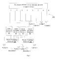
- Fig.2 is a structural diagram of an array antenna according to an embodiment of the invention.
- an Array Antenna 20 may comprise a plurality of Linear arrays 202, Uplink-Downlink Duplexers 204 and Beam-Forming Networks 206.
- the number of the linear arrays of antenna may be the n power of 2 (n is a positive integer).
- n is a positive integer.
- Each linear array is a dual-polarized linear array comprising a positive-polarized array and a negative-polarized array.
- the first linear array comprises a Positive-Polarized Array 1 and a Negatively-Polarized Array 5
- the second linear array comprises a Positive-Polarized Array 2 and a Negative-Polarized Array 6
- the third linear array comprises a Positive-Polarized Array 3 and a Negatively-Polarized Array 7
- the fourth linear array comprises a Positive-Polarized Array 4 and a Negative-Polarized Array 8.
- Each positive-polarized array or negative-polarized array comprises at least two antenna elements (see Fig.1 , which is not shown in Fig.2 ).
- the input end of Beam-Forming Network 206 is coupled with a downlink signal output end of a RF (Radio Frequency) unit, and the two output ends of the Beam-Forming Network 206 are coupled with downlink signal transmitting ends of two Uplink-Downlink Duplexers 204 respectively.
- RF Radio Frequency
- the shared transceiving ends of the two Uplink-Downlink Duplexers 204 are respectively coupled with arrays having the same polarization direction in two adjacent linear arrays, and the arrays having the same polarization direction in the two adjacent linear arrays form a beam with 65-degree beamwidth on a downlink through the Beam-Forming Network 206.
- the beamwidth of beam formed by each linear array is controlled to be about 90 degrees and then the beams with 90-degree beamwidth are combined through a beam-forming network to be transformed to a beam with 65-degree beamwidth.
- a regular scheme may be implemented by adjusting the backplate width and the sidewall height of the antenna, the backplate width is generally 0.4 ⁇ 0.6 wavelength, and the sidewall height is generally 8mm ⁇ 14mm.
- the uplink signal output ends of two uplink-downlink duplexers are coupled with the uplink signal input ends of a RF unit.
- Linear arrays uncoupled with uplink-downlink duplexers in the plurality of linear arrays (such as Positive-Polarized Array 1, Negative-Polarized Array 5, Positive-Polarized Array 4 and Negative-Polarized Array 8 of Fig.2 ) are all coupled with uplink input ends of the RF unit.
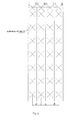
- the space(i.e., "a" as shown in Fig.1 ) between two adjacent linear arrays for transmitting downlink signals may be in a range of [0.35 ⁇ , 0.7 ⁇ ].
- the reason for taking the space between two adjacent linear arrays into account is that the correlation between two adjacent linear arrays is stronger and it is facilitated to control the beamwidth.
- the size of the array antenna must be taken into account, and thereby the space (i.e., "d” as shown in Fig.1 ) between two adjacent linear arrays for receiving uplink signals, such as, the space between the first linear array and the second linear array and the space between the third linear array and the fourth linear array, may be in a range of [ ⁇ /2, ⁇ ], wherein ⁇ is the wavelength corresponding to the center operation frequency of the array antenna.
- the Positive-Polarized Array 1 and the Negative-Polarized Array 5 being two polarization units of the first linear array, are used for receiving signals (Uplink 1 and Uplink 2).
- the Positive-Polarized Array 2 and the Negative-Polarized Array 6, the Positive-Polarized Array 3 and the Negative-Polarized Array 7, being two polarization units of the second linear array and the third linear array respectively, are divided into downlinks and uplinks by the uplink-downlink duplexers, wherein, the beam-forming networks are added on downlinks to form two beams having fixed shape for downlink transmission (i.e. Downlink 1 and Downlink 2), and the uplinks are used for receiving signals (Uplink 5, Uplink 6, Uplink 7 and Uplink 8).
- the signals transmitted from downlinks of the second and third linear array are respectively formed beams having fixed shape through the beam-forming networks, and these beams are combined and transformed from the beams having the same polarization direction.
- the beams from the Positive-Polarized Array 2 and the Positive-Polarized Array 3 are combined and transformed to a positive-polarized beam with 65-degree beamwidth
- the beams from the Negative-Polarized Array 6 and the Negative-Polarized Array 7 are combined and transformed to a negative-polarized beam with 65-degree beamwidth.
- Fig.2 shows a 2T8R array antenna based on fixed beam-forming.
- the beams combined and transformed from beams of two center linear arrays are used for transmission at the transmitting ends, and at the receiving ends, four linear arrays with totally 8 positive-polarized and negative-polarized arrays are used to receive signals. Therefore, a 2T8R array antenna is constructed and implemented.
- any two adjacent linear arrays of the array antenna may be used to form a beam with 65-degree beamwidth for the purpose of downlink transmission with a sectored pattern and a fixed beamwidth, while avoiding the issue of over-wide beamwidth caused by direct radiation of an individual linear array.
- At least one pair of adjacent linear arrays may be multiplexed as transceiving antennas.
- the linear arrays that are multiplexed as the transceiving antennas may be positioned in the center of the array antenna.
- the shaped beams have a favorable symmetry due to the symmetry on both of the antenna structure and the backplates, thus the two beams from downlinks can be overlapped well to some extent, which will be beneficial to the improvement of the downlink transmission rate of the MIMO system.
- two beams of downlink data are transmitted through two linear arrays to constitute a 2T8R array antenna.
- Fig.3 is a structure diagram of the array antenna according to another embodiment of this invention.
- two adjacent linear arrays at the most left side may be multiplexed as transceiving antennas.
- a positive-polarized beam with 65-degree beamwidth is formed using the Positive-Polarized Array 1, the Positive-Polarized Array 2 and a beam-forming network
- a negative-polarized beam with 65-degree beamwidth is formed using the Negative-Polarized Array 5, the Negative-Polarized Array 6 and a beam-forming network.
- two positive-polarized/negative-polarized beams with 65-degree beamwidth may be formed respectively using the Positive-Polarized Array 3, the Positive-Polarized Array 4 and a beam-forming network or using the Negative-Polarized Array 7, the Negative-Polarized Array 8 and a beam-forming network.
- Fig.4 is a structure diagram of the array antenna according to still another embodiment of this invention.
- four beams of downlink data may be transmitted by using four linear arrays.
- four beams with 65-degree beamwidth from downlink may be formed respectively by using the Positive-Polarized Array 1, the Positive-Polarized Array 2 and a beam-forming network, by using the Negative-Polarized Array 5, the Negative-Polarized Array 6 and a beam-forming network, by using the Positive-Polarized Array 3, the Positive-Polarized Array 4 and a beam-forming network, and by using the Negative-Polarized Array 7, the Negative-Polarized Array 8 and a beam-forming network.
- a 4T8R MIMO array antenna can be constituted.
- the array antenna of the embodiment described above may be applied to a base station to improve network service speed and link performance.
- a beam having fixed shape is formed on the downlink direction only based on two antennas having the same polarization direction.
- at least one positive-polarized beam with 65-degree beamwidth and a negative-polarized beam with 65-degree beamwidth may be formed, and downlink MIMO may be realized in a most effective manner when the two beams overlap with each other.
- the beam from downlink in the present invention may have fixed direction, and be capable of covering a complete sector.
Landscapes
- Engineering & Computer Science (AREA)
- Computer Networks & Wireless Communication (AREA)
- Signal Processing (AREA)
- Variable-Direction Aerials And Aerial Arrays (AREA)
- Radio Transmission System (AREA)
Applications Claiming Priority (1)
| Application Number | Priority Date | Filing Date | Title |
|---|---|---|---|
| PCT/CN2012/082243 WO2014047858A1 (zh) | 2012-09-28 | 2012-09-28 | 阵列天线和基站 |
Publications (3)
| Publication Number | Publication Date |
|---|---|
| EP2902931A1 true EP2902931A1 (de) | 2015-08-05 |
| EP2902931A4 EP2902931A4 (de) | 2016-04-06 |
| EP2902931B1 EP2902931B1 (de) | 2019-02-27 |
Family
ID=50386834
Family Applications (1)
| Application Number | Title | Priority Date | Filing Date |
|---|---|---|---|
| EP12885274.6A Active EP2902931B1 (de) | 2012-09-28 | 2012-09-28 | Gruppenantenne und basisstation |
Country Status (4)
| Country | Link |
|---|---|
| US (1) | US9653817B2 (de) |
| EP (1) | EP2902931B1 (de) |
| JP (1) | JP6121540B2 (de) |
| WO (1) | WO2014047858A1 (de) |
Cited By (2)
| Publication number | Priority date | Publication date | Assignee | Title |
|---|---|---|---|---|
| WO2019154362A1 (zh) * | 2018-02-06 | 2019-08-15 | 京信通信系统(中国)有限公司 | 多制式融合的天线 |
| WO2022193424A1 (zh) * | 2021-03-15 | 2022-09-22 | 罗森伯格技术有限公司 | 一种能够辐射双波束和第三波束的天线 |
Families Citing this family (3)
| Publication number | Priority date | Publication date | Assignee | Title |
|---|---|---|---|---|
| US9548852B2 (en) * | 2014-09-04 | 2017-01-17 | Commscope Technologies Llc | Antenna cross connect scheme for LTE |
| WO2021003063A1 (en) * | 2019-07-01 | 2021-01-07 | Commscope Technologies Llc | Multi-band base station antennas having mimo arrays and related methods of operation |
| US11515622B2 (en) * | 2019-07-16 | 2022-11-29 | Commscope Technologies Llc | Base station antennas having multiband beam-former arrays and related methods of operation |
Family Cites Families (15)
| Publication number | Priority date | Publication date | Assignee | Title |
|---|---|---|---|---|
| SE510995C2 (sv) * | 1997-03-24 | 1999-07-19 | Ericsson Telefon Ab L M | Aktiv sändnings/mottagnings gruppantenn |
| US6760603B1 (en) * | 1997-09-15 | 2004-07-06 | Kathrein-Werke Kg | Compact dual-polarized adaptive antenna array communication method and apparatus |
| US6304214B1 (en) * | 1999-05-07 | 2001-10-16 | Lucent Technologies Inc. | Antenna array system having coherent and noncoherent reception characteristics |
| JP2001177338A (ja) * | 1999-12-21 | 2001-06-29 | Matsushita Electric Ind Co Ltd | 移動体識別装置および移動体識別システム |
| DE60027208T2 (de) * | 2000-09-02 | 2006-08-31 | Nokia Corp. | Feststrahl-gruppenantenne, basisstation und verfahren zur signalübertragung über eine feststrahl-gruppenantenne |
| DE60128837T2 (de) * | 2001-04-16 | 2008-02-28 | Fractus, S.A. | Doppelbandige dualpolarisierte gruppenantenne |
| US20040235528A1 (en) * | 2003-05-21 | 2004-11-25 | Korisch Ilya A. | Overlapped subarray antenna feed network for wireless communication system phased array antenna |
| US7538740B2 (en) | 2006-03-06 | 2009-05-26 | Alcatel-Lucent Usa Inc. | Multiple-element antenna array for communication network |
| CN101335910B (zh) | 2007-06-29 | 2012-02-29 | 中国移动通信集团公司 | 智能天线与多输入多输出天线的复用天线系统和方法 |
| CN101635391A (zh) | 2008-07-24 | 2010-01-27 | 中兴通讯股份有限公司 | 支持mimo及智能天线技术的天线阵列 |
| EP2226890A1 (de) * | 2009-03-03 | 2010-09-08 | Hitachi Cable, Ltd. | Mobile Kommunikationsbasisstationsantenne |
| JP5386721B2 (ja) * | 2009-03-03 | 2014-01-15 | 日立金属株式会社 | 移動通信用基地局アンテナ |
| US8416142B2 (en) * | 2009-12-18 | 2013-04-09 | Kathrein-Werke Kg | Dual-polarized group antenna |
| CN101789812B (zh) | 2010-01-15 | 2013-02-27 | 重庆邮电大学 | 基于双极化天线的lte mimo通信传播信道建模方法 |
| WO2011103919A1 (en) * | 2010-02-25 | 2011-09-01 | Telefonaktiebolaget L M Ericsson (Publ) | A communication system node comprising a re-configuration network |
-
2012
- 2012-09-28 EP EP12885274.6A patent/EP2902931B1/de active Active
- 2012-09-28 US US14/431,696 patent/US9653817B2/en active Active
- 2012-09-28 JP JP2015533395A patent/JP6121540B2/ja active Active
- 2012-09-28 WO PCT/CN2012/082243 patent/WO2014047858A1/zh not_active Ceased
Cited By (2)
| Publication number | Priority date | Publication date | Assignee | Title |
|---|---|---|---|---|
| WO2019154362A1 (zh) * | 2018-02-06 | 2019-08-15 | 京信通信系统(中国)有限公司 | 多制式融合的天线 |
| WO2022193424A1 (zh) * | 2021-03-15 | 2022-09-22 | 罗森伯格技术有限公司 | 一种能够辐射双波束和第三波束的天线 |
Also Published As
| Publication number | Publication date |
|---|---|
| EP2902931A4 (de) | 2016-04-06 |
| US9653817B2 (en) | 2017-05-16 |
| JP6121540B2 (ja) | 2017-04-26 |
| EP2902931B1 (de) | 2019-02-27 |
| US20150255881A1 (en) | 2015-09-10 |
| JP2015536077A (ja) | 2015-12-17 |
| WO2014047858A1 (zh) | 2014-04-03 |
Similar Documents
| Publication | Publication Date | Title |
|---|---|---|
| TWI583145B (zh) | 射頻收發系統 | |
| US11075462B2 (en) | Antenna device | |
| US10651568B2 (en) | Base station antenna system with enhanced array spacing | |
| US20210194127A1 (en) | High gain and large bandwidth antenna incorporating a built-in differential feeding scheme | |
| JP6084690B2 (ja) | 4偏波(quadri−polarized)アンテナ発振器、4偏波アンテナ、4偏波マルチアンテナアレイ | |
| US10090591B2 (en) | Antenna system | |
| EP2741369B1 (de) | Mehrmodusantenne und basisstation dafür | |
| US10680790B2 (en) | Antenna system | |
| EP3319176A1 (de) | Gruppenantenne und netzwerkvorrichtung | |
| WO2019077813A1 (ja) | アンテナ装置 | |
| US9653817B2 (en) | Array antenna and base station | |
| EP3776874B1 (de) | Antennenanordnung zur übertragung von referenzsignalen | |
| EP2438689B1 (de) | Knoten in einem drahtlosen kommunikationssystem mit verschiedenen antennendiversitätsverfahren für uplink und downlink | |
| US9154206B2 (en) | Vertical beam design for UE-specific beamforming by matching to a CB | |
| CN106992802B (zh) | 用于用户终端的信号收发装置、用户终端和信号传输方法 | |
| US11108168B2 (en) | Antenna system for portable communication device for millimeter wave communication | |
| CN103700952B (zh) | 阵列天线和基站 | |
| CN106549226A (zh) | 射频收发系统 | |
| WO2025140021A1 (zh) | 天线装置及基站天线系统 | |
| WO2023231751A1 (zh) | 天线阵列、天线和网络设备 | |
| CN121750028A (zh) | 针对具有混合的均匀天线端口和非均匀天线端口的ue的mimo配置 | |
| CN114902580A (zh) | 利用四极化天线模块阵列实现波束的空间-极化分离的天线装置 | |
| CN103516406A (zh) | 信号收发方法及装置 |
Legal Events
| Date | Code | Title | Description |
|---|---|---|---|
| PUAI | Public reference made under article 153(3) epc to a published international application that has entered the european phase |
Free format text: ORIGINAL CODE: 0009012 |
|
| 17P | Request for examination filed |
Effective date: 20150327 |
|
| AK | Designated contracting states |
Kind code of ref document: A1 Designated state(s): AL AT BE BG CH CY CZ DE DK EE ES FI FR GB GR HR HU IE IS IT LI LT LU LV MC MK MT NL NO PL PT RO RS SE SI SK SM TR |
|
| AX | Request for extension of the european patent |
Extension state: BA ME |
|
| DAX | Request for extension of the european patent (deleted) | ||
| REG | Reference to a national code |
Ref country code: DE Ref legal event code: R079 Ref document number: 602012057309 Country of ref document: DE Free format text: PREVIOUS MAIN CLASS: G06F0019000000 Ipc: H01Q0001240000 |
|
| RA4 | Supplementary search report drawn up and despatched (corrected) |
Effective date: 20160308 |
|
| RIC1 | Information provided on ipc code assigned before grant |
Ipc: H01Q 21/06 20060101ALI20160302BHEP Ipc: H04B 7/10 20060101ALI20160302BHEP Ipc: H01Q 21/26 20060101ALI20160302BHEP Ipc: H04B 7/06 20060101ALI20160302BHEP Ipc: H01Q 1/24 20060101AFI20160302BHEP |
|
| STAA | Information on the status of an ep patent application or granted ep patent |
Free format text: STATUS: EXAMINATION IS IN PROGRESS |
|
| 17Q | First examination report despatched |
Effective date: 20170324 |
|
| GRAP | Despatch of communication of intention to grant a patent |
Free format text: ORIGINAL CODE: EPIDOSNIGR1 |
|
| STAA | Information on the status of an ep patent application or granted ep patent |
Free format text: STATUS: GRANT OF PATENT IS INTENDED |
|
| INTG | Intention to grant announced |
Effective date: 20181005 |
|
| GRAS | Grant fee paid |
Free format text: ORIGINAL CODE: EPIDOSNIGR3 |
|
| GRAA | (expected) grant |
Free format text: ORIGINAL CODE: 0009210 |
|
| STAA | Information on the status of an ep patent application or granted ep patent |
Free format text: STATUS: THE PATENT HAS BEEN GRANTED |
|
| AK | Designated contracting states |
Kind code of ref document: B1 Designated state(s): AL AT BE BG CH CY CZ DE DK EE ES FI FR GB GR HR HU IE IS IT LI LT LU LV MC MK MT NL NO PL PT RO RS SE SI SK SM TR |
|
| REG | Reference to a national code |
Ref country code: GB Ref legal event code: FG4D |
|
| REG | Reference to a national code |
Ref country code: CH Ref legal event code: EP |
|
| REG | Reference to a national code |
Ref country code: AT Ref legal event code: REF Ref document number: 1102672 Country of ref document: AT Kind code of ref document: T Effective date: 20190315 |
|
| REG | Reference to a national code |
Ref country code: IE Ref legal event code: FG4D |
|
| REG | Reference to a national code |
Ref country code: DE Ref legal event code: R096 Ref document number: 602012057309 Country of ref document: DE |
|
| REG | Reference to a national code |
Ref country code: NL Ref legal event code: MP Effective date: 20190227 |
|
| REG | Reference to a national code |
Ref country code: LT Ref legal event code: MG4D |
|
| PG25 | Lapsed in a contracting state [announced via postgrant information from national office to epo] |
Ref country code: PT Free format text: LAPSE BECAUSE OF FAILURE TO SUBMIT A TRANSLATION OF THE DESCRIPTION OR TO PAY THE FEE WITHIN THE PRESCRIBED TIME-LIMIT Effective date: 20190627 Ref country code: SE Free format text: LAPSE BECAUSE OF FAILURE TO SUBMIT A TRANSLATION OF THE DESCRIPTION OR TO PAY THE FEE WITHIN THE PRESCRIBED TIME-LIMIT Effective date: 20190227 Ref country code: FI Free format text: LAPSE BECAUSE OF FAILURE TO SUBMIT A TRANSLATION OF THE DESCRIPTION OR TO PAY THE FEE WITHIN THE PRESCRIBED TIME-LIMIT Effective date: 20190227 Ref country code: NO Free format text: LAPSE BECAUSE OF FAILURE TO SUBMIT A TRANSLATION OF THE DESCRIPTION OR TO PAY THE FEE WITHIN THE PRESCRIBED TIME-LIMIT Effective date: 20190527 Ref country code: NL Free format text: LAPSE BECAUSE OF FAILURE TO SUBMIT A TRANSLATION OF THE DESCRIPTION OR TO PAY THE FEE WITHIN THE PRESCRIBED TIME-LIMIT Effective date: 20190227 Ref country code: LT Free format text: LAPSE BECAUSE OF FAILURE TO SUBMIT A TRANSLATION OF THE DESCRIPTION OR TO PAY THE FEE WITHIN THE PRESCRIBED TIME-LIMIT Effective date: 20190227 |
|
| PG25 | Lapsed in a contracting state [announced via postgrant information from national office to epo] |
Ref country code: BG Free format text: LAPSE BECAUSE OF FAILURE TO SUBMIT A TRANSLATION OF THE DESCRIPTION OR TO PAY THE FEE WITHIN THE PRESCRIBED TIME-LIMIT Effective date: 20190527 Ref country code: GR Free format text: LAPSE BECAUSE OF FAILURE TO SUBMIT A TRANSLATION OF THE DESCRIPTION OR TO PAY THE FEE WITHIN THE PRESCRIBED TIME-LIMIT Effective date: 20190528 Ref country code: IS Free format text: LAPSE BECAUSE OF FAILURE TO SUBMIT A TRANSLATION OF THE DESCRIPTION OR TO PAY THE FEE WITHIN THE PRESCRIBED TIME-LIMIT Effective date: 20190627 Ref country code: HR Free format text: LAPSE BECAUSE OF FAILURE TO SUBMIT A TRANSLATION OF THE DESCRIPTION OR TO PAY THE FEE WITHIN THE PRESCRIBED TIME-LIMIT Effective date: 20190227 Ref country code: LV Free format text: LAPSE BECAUSE OF FAILURE TO SUBMIT A TRANSLATION OF THE DESCRIPTION OR TO PAY THE FEE WITHIN THE PRESCRIBED TIME-LIMIT Effective date: 20190227 Ref country code: RS Free format text: LAPSE BECAUSE OF FAILURE TO SUBMIT A TRANSLATION OF THE DESCRIPTION OR TO PAY THE FEE WITHIN THE PRESCRIBED TIME-LIMIT Effective date: 20190227 |
|
| REG | Reference to a national code |
Ref country code: AT Ref legal event code: MK05 Ref document number: 1102672 Country of ref document: AT Kind code of ref document: T Effective date: 20190227 |
|
| PG25 | Lapsed in a contracting state [announced via postgrant information from national office to epo] |
Ref country code: SK Free format text: LAPSE BECAUSE OF FAILURE TO SUBMIT A TRANSLATION OF THE DESCRIPTION OR TO PAY THE FEE WITHIN THE PRESCRIBED TIME-LIMIT Effective date: 20190227 Ref country code: RO Free format text: LAPSE BECAUSE OF FAILURE TO SUBMIT A TRANSLATION OF THE DESCRIPTION OR TO PAY THE FEE WITHIN THE PRESCRIBED TIME-LIMIT Effective date: 20190227 Ref country code: IT Free format text: LAPSE BECAUSE OF FAILURE TO SUBMIT A TRANSLATION OF THE DESCRIPTION OR TO PAY THE FEE WITHIN THE PRESCRIBED TIME-LIMIT Effective date: 20190227 Ref country code: CZ Free format text: LAPSE BECAUSE OF FAILURE TO SUBMIT A TRANSLATION OF THE DESCRIPTION OR TO PAY THE FEE WITHIN THE PRESCRIBED TIME-LIMIT Effective date: 20190227 Ref country code: EE Free format text: LAPSE BECAUSE OF FAILURE TO SUBMIT A TRANSLATION OF THE DESCRIPTION OR TO PAY THE FEE WITHIN THE PRESCRIBED TIME-LIMIT Effective date: 20190227 Ref country code: DK Free format text: LAPSE BECAUSE OF FAILURE TO SUBMIT A TRANSLATION OF THE DESCRIPTION OR TO PAY THE FEE WITHIN THE PRESCRIBED TIME-LIMIT Effective date: 20190227 Ref country code: ES Free format text: LAPSE BECAUSE OF FAILURE TO SUBMIT A TRANSLATION OF THE DESCRIPTION OR TO PAY THE FEE WITHIN THE PRESCRIBED TIME-LIMIT Effective date: 20190227 Ref country code: AL Free format text: LAPSE BECAUSE OF FAILURE TO SUBMIT A TRANSLATION OF THE DESCRIPTION OR TO PAY THE FEE WITHIN THE PRESCRIBED TIME-LIMIT Effective date: 20190227 |
|
| REG | Reference to a national code |
Ref country code: DE Ref legal event code: R097 Ref document number: 602012057309 Country of ref document: DE |
|
| PG25 | Lapsed in a contracting state [announced via postgrant information from national office to epo] |
Ref country code: PL Free format text: LAPSE BECAUSE OF FAILURE TO SUBMIT A TRANSLATION OF THE DESCRIPTION OR TO PAY THE FEE WITHIN THE PRESCRIBED TIME-LIMIT Effective date: 20190227 Ref country code: SM Free format text: LAPSE BECAUSE OF FAILURE TO SUBMIT A TRANSLATION OF THE DESCRIPTION OR TO PAY THE FEE WITHIN THE PRESCRIBED TIME-LIMIT Effective date: 20190227 |
|
| PG25 | Lapsed in a contracting state [announced via postgrant information from national office to epo] |
Ref country code: AT Free format text: LAPSE BECAUSE OF FAILURE TO SUBMIT A TRANSLATION OF THE DESCRIPTION OR TO PAY THE FEE WITHIN THE PRESCRIBED TIME-LIMIT Effective date: 20190227 |
|
| PLBE | No opposition filed within time limit |
Free format text: ORIGINAL CODE: 0009261 |
|
| STAA | Information on the status of an ep patent application or granted ep patent |
Free format text: STATUS: NO OPPOSITION FILED WITHIN TIME LIMIT |
|
| 26N | No opposition filed |
Effective date: 20191128 |
|
| PG25 | Lapsed in a contracting state [announced via postgrant information from national office to epo] |
Ref country code: SI Free format text: LAPSE BECAUSE OF FAILURE TO SUBMIT A TRANSLATION OF THE DESCRIPTION OR TO PAY THE FEE WITHIN THE PRESCRIBED TIME-LIMIT Effective date: 20190227 |
|
| PG25 | Lapsed in a contracting state [announced via postgrant information from national office to epo] |
Ref country code: TR Free format text: LAPSE BECAUSE OF FAILURE TO SUBMIT A TRANSLATION OF THE DESCRIPTION OR TO PAY THE FEE WITHIN THE PRESCRIBED TIME-LIMIT Effective date: 20190227 |
|
| PG25 | Lapsed in a contracting state [announced via postgrant information from national office to epo] |
Ref country code: MC Free format text: LAPSE BECAUSE OF FAILURE TO SUBMIT A TRANSLATION OF THE DESCRIPTION OR TO PAY THE FEE WITHIN THE PRESCRIBED TIME-LIMIT Effective date: 20190227 |
|
| REG | Reference to a national code |
Ref country code: CH Ref legal event code: PL |
|
| PG25 | Lapsed in a contracting state [announced via postgrant information from national office to epo] |
Ref country code: LU Free format text: LAPSE BECAUSE OF NON-PAYMENT OF DUE FEES Effective date: 20190928 Ref country code: CH Free format text: LAPSE BECAUSE OF NON-PAYMENT OF DUE FEES Effective date: 20190930 Ref country code: IE Free format text: LAPSE BECAUSE OF NON-PAYMENT OF DUE FEES Effective date: 20190928 Ref country code: LI Free format text: LAPSE BECAUSE OF NON-PAYMENT OF DUE FEES Effective date: 20190930 |
|
| REG | Reference to a national code |
Ref country code: BE Ref legal event code: MM Effective date: 20190930 |
|
| PG25 | Lapsed in a contracting state [announced via postgrant information from national office to epo] |
Ref country code: BE Free format text: LAPSE BECAUSE OF NON-PAYMENT OF DUE FEES Effective date: 20190930 |
|
| PG25 | Lapsed in a contracting state [announced via postgrant information from national office to epo] |
Ref country code: CY Free format text: LAPSE BECAUSE OF FAILURE TO SUBMIT A TRANSLATION OF THE DESCRIPTION OR TO PAY THE FEE WITHIN THE PRESCRIBED TIME-LIMIT Effective date: 20190227 |
|
| PG25 | Lapsed in a contracting state [announced via postgrant information from national office to epo] |
Ref country code: MT Free format text: LAPSE BECAUSE OF FAILURE TO SUBMIT A TRANSLATION OF THE DESCRIPTION OR TO PAY THE FEE WITHIN THE PRESCRIBED TIME-LIMIT Effective date: 20190227 Ref country code: HU Free format text: LAPSE BECAUSE OF FAILURE TO SUBMIT A TRANSLATION OF THE DESCRIPTION OR TO PAY THE FEE WITHIN THE PRESCRIBED TIME-LIMIT; INVALID AB INITIO Effective date: 20120928 |
|
| PG25 | Lapsed in a contracting state [announced via postgrant information from national office to epo] |
Ref country code: MK Free format text: LAPSE BECAUSE OF FAILURE TO SUBMIT A TRANSLATION OF THE DESCRIPTION OR TO PAY THE FEE WITHIN THE PRESCRIBED TIME-LIMIT Effective date: 20190227 |
|
| PGFP | Annual fee paid to national office [announced via postgrant information from national office to epo] |
Ref country code: DE Payment date: 20250819 Year of fee payment: 14 |
|
| PGFP | Annual fee paid to national office [announced via postgrant information from national office to epo] |
Ref country code: GB Payment date: 20250814 Year of fee payment: 14 |
|
| PGFP | Annual fee paid to national office [announced via postgrant information from national office to epo] |
Ref country code: FR Payment date: 20250821 Year of fee payment: 14 |