EP2903015A1 - Disjoncteur - Google Patents
Disjoncteur Download PDFInfo
- Publication number
- EP2903015A1 EP2903015A1 EP13840500.6A EP13840500A EP2903015A1 EP 2903015 A1 EP2903015 A1 EP 2903015A1 EP 13840500 A EP13840500 A EP 13840500A EP 2903015 A1 EP2903015 A1 EP 2903015A1
- Authority
- EP
- European Patent Office
- Prior art keywords
- wiring
- circuit breaker
- housing
- wire
- screw
- Prior art date
- Legal status (The legal status is an assumption and is not a legal conclusion. Google has not performed a legal analysis and makes no representation as to the accuracy of the status listed.)
- Granted
Links
Images




Classifications
-
- H—ELECTRICITY
- H01—ELECTRIC ELEMENTS
- H01H—ELECTRIC SWITCHES; RELAYS; SELECTORS; EMERGENCY PROTECTIVE DEVICES
- H01H71/00—Details of the protective switches or relays covered by groups H01H73/00 - H01H83/00
- H01H71/08—Terminals; Connections
-
- H—ELECTRICITY
- H01—ELECTRIC ELEMENTS
- H01H—ELECTRIC SWITCHES; RELAYS; SELECTORS; EMERGENCY PROTECTIVE DEVICES
- H01H71/00—Details of the protective switches or relays covered by groups H01H73/00 - H01H83/00
- H01H71/02—Housings; Casings; Bases; Mountings
-
- H—ELECTRICITY
- H01—ELECTRIC ELEMENTS
- H01R—ELECTRICALLY-CONDUCTIVE CONNECTIONS; STRUCTURAL ASSOCIATIONS OF A PLURALITY OF MUTUALLY-INSULATED ELECTRICAL CONNECTING ELEMENTS; COUPLING DEVICES; CURRENT COLLECTORS
- H01R4/00—Electrically-conductive connections between two or more conductive members in direct contact, i.e. touching one another; Means for effecting or maintaining such contact; Electrically-conductive connections having two or more spaced connecting locations for conductors and using contact members penetrating insulation
- H01R4/28—Clamped connections, spring connections
- H01R4/38—Clamped connections, spring connections utilising a clamping member acted on by screw or nut
Definitions
- the present invention relates to a circuit breaker in the field of power distribution, and more particularly, to a circuit breaker that may realize a hybrid junction of various wires.
- the existing circuit breaker particularly a miniature circuit breaker realizes its wiring function through the reliable connection between terminals and loop wires.
- the circuit breaker is mainly used for protecting end of the lines in the early stage. With regard to this loop, it may be obtained and applied as long as one wiring function of the wire is realized.
- branched wiring is usually performed on each phase of a circuit breaker in a next-stage parallel system or parallel lines due to the need of distribution of power system or circuit design. For example, when the line is required from the outlet end of the master switch into multiple parallel branches, it usually employs a manner of performing parallel wiring on the same phase terminals of the circuit breakers on these parallel branches.
- the type of wires that can be connected to the circuit breaker is increased from one type initially to two types.
- the increased wiring type causes various permutation and combination of wires that may be connected to the existing circuit breaker.
- the wires commonly used by the circuit breaker in the market include: multi-strand wires, single-strand wires, bus (bus bar) and wires having annular joints used for realizing quick wiring. Therefore, a circuit breaker that can realize the wiring function of combination of any two commonly used wires will adapt for the market demands more quickly.
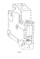
- the first technical scheme as shown in Figure 1 , wherein wiring boards and terminals are mounted within a housing of a circuit breaker.
- the terminal includes a wire trap that can generate relative movement with the wiring board, and a screw that is in screw-thread fit with the wire trap.
- a wire is connected between the wire trap and the wiring board, and is fastened through the screw to realize the wiring function of the circuit breaker.
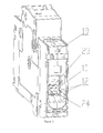
- the second technical scheme as shown in Figure 2 , which is the most common wiring manner of the circuit breaker at present.
- a second wiring board is added on the movement direction of the wire trap. This wiring board is equipotential with the original first wiring board.
- the screw in screw-thread fit with the wire trap traverses said second wiring board, and the bus (bus bar) wiring function is realized through the screw and the second wiring board.
- the bus (bus bar) function used in the first technical solution can also be designed.
- the second technical solution separates the bus (bus bar) wiring function from the conventional wiring function and makes the two functions independent mutually through the two wiring boards. This enables the second technical solution to realize all the wiring functions of the first technical solution while realizing the bus (bus bar) wiring function; but, it is inevitably to make the terminals and wiring board structure relatively complicated.
- the technical problem to be solved by the present invention is to provide a circuit breaker which has simple structure, can realize a hybrid junction of various wires, and can provide safety for connection of wires.
- the present invention discloses a circuit breaker, which includes a housing, wiring boards 1 and terminals 2 disposed within the housing.
- the terminal 2 includes a screw 6, a press board 7 and a wire trap 8 provided with a incoming line hole and a wiring space, said screw 6 passes through a threaded hole on the top end face 29 of the wire trap 8 and contacts with the press board 7 which is able to lift up and down and embedded in the wire trap 8.
- Said wiring board 1 traverses the wire trap 8, and divides the wiring space of the wire trap 8 into two independent wiring spaces 23, 24.
- a first wiring space 23 is formed among the wiring board 1, the press board 7 and the side walls of the wire trap 8.
- a second wiring space 24 is formed among the wiring board 1, the bottom end face 14 of the wire trap 8 and the side walls of the wire trap 8.
- a first line hole 4 is provided in the housing at a position above the screw 6 of the terminal 2.
- the press board 7 and the wire trap 8 perform a relative displacement with the wiring board 1 under the action of the screw 6 to compress the two independent wiring spaces so as to realize the connection between wires.
- said inner wall of the housing is provided with a guide board 12 for guiding the wires connected to the two independent wiring spaces 23, 24 on an incoming line direction that connects the wires with the terminal 2.
- the wires can be conveniently guided by the guide board to respectively enter the two independent wiring spaces.
- said inside of the housing is provided with a wiring channel 20 for holding a wire exposed end on the incoming line direction that connects the wires with the terminal 2.
- the wire exposed end when the wire is connected to the terminal is disposed in the housing through the wiring channel.
- the creepage distance and the electrical clearance are increased, which effectively isolates the security risks between adjacent wires after the wire is connected to the multipole circuit breaker, thus realizing electrical safety.
- the circuit breaker further includes a wiring bar annex 22 which may be connected to a bus (bus bar) wire.
- the wiring bar annex 22 includes a connecting bar 18 connected to any one of the two independent wiring spaces 23, 24, and an insulation baffle 16 used for fixing the connecting bar 18 and provided with a incoming line hole.
- the insulation baffle 16 is fixed on the housing along the incoming line direction of the wire.
- the hybrid junction of the wires having bus bar type's connection is realized through the wiring bar annex, thus expanding the types of the wires that can be connected to the circuit breaker in a hybrid manner.
- the connecting bar 18 is provided with a wiring screw 17 which may be connected to a wire having annular joints
- the housing is provided with a second line hole 3 at a position above the wiring screw 17 of the wiring bar annex 22.
- the hybrid junction with the wires having annular joints can be realized through the setting of adding the wiring screw, thus expanding the types of the wires that can be connected to the circuit breaker in a hybrid manner.
- the insulation baffle 16 is provided with a stop pin 15, and the stop pin 15 is mutually engaged with a stop gear 19 disposed on the corresponding position of the housing to realize self-locking and fixing of the insulation baffle 16.
- This is a specific insulation baffle fixing structure.
- the mutual engaging of the stop pin and the stop gear not only can guarantee the installation intensity, but also is convenient to assemble and disassemble.
- the circuit breaker forms the wiring channel 20 having a distance not smaller than the distance between the first line hole 4 and the second line hole 3 and holding the wire exposed end on the incoming line direction that connects the wires with the terminal 2 in the housing. Due to the design of the first line hole, the second line hole and the additionally disposed wiring bar annex, a pair of wiring channels having a distance not smaller than the distance between the first line hole and the second line hole on the incoming line direction that connects the wires with the terminal in the housing are formed, thus being capable of realizing electrical safety.
- the connecting bar 18 includes an electrical connecting element 27 embedded into any one of the two independent wiring spaces 23, 24, and a mounting element 28 fixedly connected to the electrical connecting element 27.
- the width of the mounting element 28 is larger than the width of the electrical connecting element 27, and the wiring screw 17 is disposed on the mounting element 28. This is a specific connecting bar structure.
- the housing is provided with a locating surface 10 corresponding to connecting bar end face 21 at the two sides of the mounting element 28 of the connecting bar 18.
- the connecting bar end faces 21 are embedded into the locating surface 10. While ensuring the connecting bar connected into the wiring space to realize reliable guide, the locating surface offset counteract torque generated by the wiring screw of the connecting bar when the connecting bar is connected to the wire having annular joints, prevents the connecting bar from swinging along the torque plane, and ensures the reliable wiring function of the wiring bar annex.
- the wiring space of the wire trap is divided into two independent wiring spaces, and equivalently separating out two terminals, wherein the two terminals may finish respective wiring functions thereof and do not interfere with each other.
- the invention has simple structure, and also realizes a wiring function of hybrid junction of single-strand wires with different diameter while reserving all the wiring functions of the existing first technical solution. Further, the invention may also be additionally provided with the wiring bar annex connected to the terminal to realize the hybrid junction with the wires having bus (bus bar) type joints in the second technical solution in the case of not increasing the wiring board, thus expanding the types of the wires that can be connected to the circuit breaker in a hybrid manner.
- the invention is provided with the wiring screw on the connecting bar annex to realize hybrid junction with the wires having annular joints, thus further expanding the types of the wires that can be connected to the circuit breaker in a hybrid manner.
- the wiring channel is equipped within the housing, and the wire exposed end when the wire is connected to the terminal is disposed within the housing through the wiring channel. Moreover, the creepage distance and the electrical clearance are increased, which effectively isolates the security risks between adjacent wires after the wire is connected to the multipole circuit breaker, thus realizing electrical safety.
- the present invention discloses a circuit breaker, which includes a housing, wiring boards 1 and terminals 2 equipped within the housing.
- Each terminal 2 includes a screw 6, a press board 7 and a wire trap 8 provided with a incoming line hole and a wiring space.
- the screw 6 passes through a threaded hole on the top end face 29 of the wire trap 8 and contacts with the press board 7 which is able to lift up and down and embedded in the wire trap 8.
- the wiring board 1 traverses the wire trap 8 and divides the wiring space of the wire trap 8 into two independent wiring spaces 23, 24.
- a first wiring space 23 is formed among the wiring board 1, the press board 7 and the side walls of the wire trap 8.
- a second wiring space 24 is formed among the wiring board 1, the bottom end face 14 of the wire trap 8 and the side walls of the wire trap 8.
- the housing is provided with a first line hole 4 at a position above the screw 6 of the terminal 2.
- the press board 7 and the wire trap 8 perform a relative displacement with the wiring board 1 under the action of the screw 6 to compress the two independent wiring spaces so as to realize the connection between wires.
- the circuit breaker further of the present invention further includes a wiring bar annex 22 which may be connected to a bus (bus bar) wire.
- the wiring bar annex 22 includes a connecting bar 18 connected to any one of the two independent wiring spaces 23, 24, and an insulation baffle 16 used for fixing the connecting bar 18 and provided with a incoming line hole.
- the insulation baffle 16 is fixed on the housing along the incoming line direction of the wire. Further, the connecting bar 18 is provided with a wiring screw 17 which may be connected to a wire having annular joint, and the housing is provided with a second line hole 3 at a position above the wiring screw 17 of the wiring bar annex 22.
- a wiring space of the wire trap is divided into two independent wiring spaces, and equivalently separating out two terminals, wherein the two terminals may finish respective wiring functions thereof and do not interfere with each other.
- the invention has simple structure, and also realizes a hybrid junction of single-strand wires with different diameter while reserving all the wiring functions of the existing first technical solution. Further, the invention may also be additionally provided with a wiring bar annex connected to the terminal to realize hybrid junction with the wires having bus bar type joints in the existing second technical solution in the case of not increasing a wiring board, thus expanding the types of the wires that can be connected in a hybrid manner in the circuit breaker.
- the invention is provided with the wiring screw on the connecting bar annex to realize hybrid junction with the wires having annular joint, thus further expanding the types of the wires that can be connected in a hybrid manner in the circuit breaker.
- the wiring channel is disposed in the housing, and the wire exposed end when the wire is connected to the terminal is disposed in the housing through the wiring channel. Moreover, the creepage distance and the electrical clearances are increased, which effectively isolates the security risks between adjacent wires after the wire is connected to the multipole circuit breaker, thus realizing electrical safety.
- the circuit breaker of the embodiment includes an enclosed housing.
- the housing includes insulated first housing 5A and second housing 5B.
- the insides of the first housing 5A and the second housing 5B are provided with spaces for holding each part of the circuit breaker, and various splicing and fastening components, and an operating mechanism, a contact device, a trip unit, an explosion chamber and so on of the circuit breaker are respectively fixed inside the two housings, then the two housings are spliced and fixed to form the complete circuit breaker, meanwhile, the internal components to achieve a reliable secured and sealed.
- the terminal 2 includes a wire trap 8 mutually fit with the wiring board 1 and capable of generating relative movement with the wiring board 1, a screw 6 in screw thread fit with the wire trap 8, and a press board 7 mutually fit with the screw 6 and generating relative movement with the wiring board 1 with the pushing of the screw 6.
- the wire trap 8 is provided with a incoming line hole and a wiring space, and is in a hollow rectangle structure, wherein the hollow portion thereof is the wiring space.
- the top end face 29 of the wire trap 8 is provided with a threaded hole.
- the screw 6 is disposed in the threaded hole.
- the screw thread end of the screw 6 is contacted with the press board 7 which is able to lift up and down and embedded in the wire trap 8 through the threaded hole.
- the wiring board 1 also traverses the interior of the wire trap 8.
- the wiring board 1 is fixed on the housing to divide the wiring space of the wire trap 8 into two mutually independent wiring spaces.
- a first wiring space 23 is formed among the wiring board 1, the press board 7 and the side walls of the wire trap 8.
- a second wiring space 24 is formed among the wiring board 1, the bottom end face 14 of the wire trap 8 and the side walls of the wire trap 8.
- the housing is provided with a first line hole 4 at a position above the screw 6 of the terminal 2.
- a screw driver may enter the housing through the first line hole 4 to tighten the screw, when installing the wires.
- the inner wall of the first housing 5A and the inner wall of the second housing 5B are provided with a convex guide board 12 for guiding the wires connected to the two independent wiring spaces on a incoming line direction that connects the wires with the terminal 2.
- the end face of the guide board 12 is flush with the end face of the wiring board 1. The wires may be guided conveniently to enter separately the corresponding two independent wiring spaces through the guide board 12.
- the screw 6 When connecting the wires, the screw 6 is screwed to fasten. Firstly, the press board 7 will move towards the wiring board 1 constantly with the pushing of the screw 6 to fix the wires between the press board 7 and the wiring board 1 and realize the wiring function of the first wiring space 23. The screw 6 is tightened continuously. After the press board end face 9 is contacted with the upper end face 11 of the wiring board, the screw 6 will not move downwards. The wire trap 8 under the action of screw thread fit moves upwards along the screw 6.
- the bottom end face 14 of the wire trap moves towards the lower end face 13 of the wiring board to compact the wire between the wire trap 8 and the wiring board 1, thus realizing the wiring function of the second wiring space 24 and finally finishing the wiring function of any two commonly used wires, while both the two wiring spaces can be considered as independent terminals.
- the embodiment has simple structure.
- the wiring space of the wire trap is divided into two independent wiring spaces, wherein the two wiring spaces can finish respective wiring functions.
- the connection of common wires like multi-strand wires, single-strand wires and the like can be realized; meanwhile, the wiring function of hybrid junction of single-strand wires with different diameter is also realized.
- the wiring space of the wire trap is divided into two mutually independent wiring spaces. It is apparent for those skilled in the art to expand the technical solution into a plurality of wiring boards, wherein these wiring boards are all at the same electrical potential.
- the space of the wire trap is divided into a plurality of independent spaces, thus realizing hybrid junction of a plurality of commonly used wires.
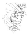
- the wire connecting solution of the two independent wiring spaces formed through the first line hole 4, the terminal 2 and the wiring board 1 is suitable for commonly used wiring boards and terminals, and has a certain restriction on the types of the wire joints that can be installed. Therefore, in order to expand the application scope of the circuit breaker so as to adapt to more types of wire joints, the circuit breaker may also be additionally provided with a wiring bar annex 22 that may be connected to a bus (bus bar) wire according to the wiring conditions. As shown in Figs. 7 to 9 , the wiring bar annex 22 includes a connecting bar 18 connected to any one of the two independent wiring spaces 23, 24, and an insulation baffle 16 used for fixing the connecting bar 18 and provided with a incoming line hole.
- the insulation baffle 16 is fixed on the housing along the incoming line direction of the wire.
- the connecting bar 18 is connected into any one of the independent wiring spaces of the terminal 2 and a certain installation torque is kept.
- the installation of the wiring bar annex 22 is finished, thus realizing the expansion of the wiring function and ensures electrical safety.
- the embodiment realizes hybrid junction with the bus (bus bar) wire through the wiring bar annex 22.
- the connecting bar 18 is provided with a wiring screw 17 which may be connected to a wire having annular joint
- the housing is provided with a second line hole 3 at a position above the wiring screw 17 of the wiring bar annex 22.
- a screw driver may enter the housing through the second line hole 3 to tighten the screw 17.
- the second line hole 3 and the first line hole 4 are disposed in parallel and extend along the fit plane of the first housing 5A and the second housing 5B.
- the embodiment realizes hybrid junction with the bus (bus bar) wire through the wiring bar annex 22.
- the embodiment realizes hybrid junction with the wire having annular joint through the setting of increasing the wiring screw.
- the connecting bar 18 in the embodiment includes a electrical connecting portion 27 embedded into any one of the two independent wiring spaces 23, 24, and an mounting element 28 fixedly connected to the electrical connecting element 27.
- the electrical connecting element 27 is a square cylinder, and the width of the mounting element 28 is larger than the electrical connecting element 27; in this way, the portion of the mounting element 28 exceeding the electrical connecting element 27 is just formed a flange portion, i.e., forming two wiring channel end faces 21.
- the wiring screw 17 is disposed on the mounting element 28.
- the first housing 5A and the second housing 5B are provided with a locating surface 10 corresponding to connecting bar end faces 21 at the two sides of the mounting element 28 of the connecting bar 18.
- the connecting bar end faces 21 are embedded into said locating surface 10. While ensuring the connecting bar 18 connected into said wiring space to realize reliable guide, the locating surface 10 offset the counteract torque generated by the wiring screw 17 of the connecting bar 18 when the connecting bar 18 is connected to the wire having annular joint, prevents the connecting bar 18 from swinging along the torque plane, and ensures the reliable wiring function of the wiring bar annex 22.
- the insulation baffle 16 is provided with a stop pin 15, and the stop pin 15 is mutually engaged with a stop gear 19 disposed on a corresponding position of the housing to realize self-locking and fixing of the insulation baffle 16.
- the stop pin 15 and the stop gear 19 are mutually engaged, which prevents the insulation baffle 16 from sliding on or falling off the housing along the installing direction to realize said self-locking of the insulation baffle 16 and ensures the safety of said wiring bar annex 22, and is also convenient to assemble and disassemble.
- the embodiment employs two pairs of line holes (first line hole 4 and second line hole 3) disposed in parallel and the design of the wiring bar annex 22 that can be additionally disposed to form the wiring channel 20 having a distance not smaller than the distance between the first line hole 4 and the second line hole 3 and holding the wire exposed end on the incoming line direction that connects the wires with the terminal 2 in the housing. Due to the wiring channel 20, the wiring opening of the terminal 2 is equivalent to be embedded into the interior of the housing and the wires are connected to the interior of the terminal 2. Even if partial metal is exposed outside the terminal 2, the wiring channel 20 may also isolate the exposed portion.
- the embodiment prevents the security risks brought by that the wire exposed end is disposed outside the housing of the circuit breaker, and prevents the security risks brought by that too small of the electrical clearance and the creepage distance between two adjacent wires after the wires of the multi pole circuit breaker are connected.
- the electrical safety function realized by the embodiment through the wiring channel 20 may also be realized in a common circuit breaker that does not have two pairs of line holes and the design of additionally arranging the wiring bar annex, as long as a certain protection channel is reserved at the incoming line opening of the wire of the terminal in the housing, which will certainly increase the volume of the circuit breaker.
Landscapes
- Connections Arranged To Contact A Plurality Of Conductors (AREA)
- Breakers (AREA)
- Distribution Board (AREA)
Applications Claiming Priority (2)
| Application Number | Priority Date | Filing Date | Title |
|---|---|---|---|
| CN2012204952823U CN202816824U (zh) | 2012-09-25 | 2012-09-25 | 一种断路器 |
| PCT/CN2013/073184 WO2014048095A1 (fr) | 2012-09-25 | 2013-03-26 | Disjoncteur |
Publications (3)
| Publication Number | Publication Date |
|---|---|
| EP2903015A1 true EP2903015A1 (fr) | 2015-08-05 |
| EP2903015A4 EP2903015A4 (fr) | 2016-06-08 |
| EP2903015B1 EP2903015B1 (fr) | 2019-12-11 |
Family
ID=47875667
Family Applications (1)
| Application Number | Title | Priority Date | Filing Date |
|---|---|---|---|
| EP13840500.6A Active EP2903015B1 (fr) | 2012-09-25 | 2013-03-26 | Disjoncteur |
Country Status (7)
| Country | Link |
|---|---|
| US (1) | US9490092B2 (fr) |
| EP (1) | EP2903015B1 (fr) |
| CN (1) | CN202816824U (fr) |
| CA (1) | CA2881855C (fr) |
| ES (1) | ES2769833T3 (fr) |
| MX (1) | MX358386B (fr) |
| WO (1) | WO2014048095A1 (fr) |
Cited By (1)
| Publication number | Priority date | Publication date | Assignee | Title |
|---|---|---|---|---|
| EP3225360A1 (fr) * | 2016-03-29 | 2017-10-04 | Schneider Electric Industries SAS | Accessoire de serrage au bon couple, et appareil de protection électrique comportant au moins une borne raccordée au moyen d'un tel accessoire |
Families Citing this family (15)
| Publication number | Priority date | Publication date | Assignee | Title |
|---|---|---|---|---|
| CN102881528B (zh) * | 2012-09-25 | 2015-03-18 | 上海诺雅克电气有限公司 | 一种断路器 |
| CN202816824U (zh) * | 2012-09-25 | 2013-03-20 | 上海诺雅克电气有限公司 | 一种断路器 |
| US9728972B2 (en) * | 2014-08-20 | 2017-08-08 | Qfe 002 Llc | Alternative energy bus bar by pass breaker, methods of use and installation |
| CN106356253B (zh) * | 2015-07-16 | 2018-07-27 | 上海良信电器股份有限公司 | 一种压板式接线端子 |
| CN106356255B (zh) * | 2015-07-16 | 2018-06-01 | 上海良信电器股份有限公司 | 一种推杆式接线端子 |
| CN106356256B (zh) * | 2015-07-16 | 2018-09-21 | 上海良信电器股份有限公司 | 一种喉箍式接线端子 |
| CN106356254B (zh) * | 2015-07-16 | 2018-07-27 | 上海良信电器股份有限公司 | 一种连杆式接线端子 |
| CN111128615A (zh) * | 2020-01-21 | 2020-05-08 | 浙江天正电气股份有限公司 | 一种多p断路器的接线结构 |
| CN111640631A (zh) * | 2020-07-02 | 2020-09-08 | 乐清市高科环保电子有限公司 | 一种断路器用的接线装置 |
| JP7839143B2 (ja) | 2020-07-24 | 2026-04-01 | ベイシス エヌゼット リミテッド | 改良された配電盤 |
| CN114628200A (zh) * | 2020-12-09 | 2022-06-14 | 德力西电气有限公司 | 一种用于电动车的断路器壳体结构和断路器 |
| CN114743839B (zh) * | 2020-12-23 | 2023-10-24 | 上海华宿电气股份有限公司 | 一种多极导线连接结构 |
| CN112863951B (zh) * | 2021-01-05 | 2022-09-02 | 三峡大学 | 一种电气工程配电断路器 |
| CA219264S (en) | 2022-08-19 | 2024-12-10 | Osho Ltd | Electrical distribution board |
| CA219265S (en) | 2022-08-19 | 2024-12-11 | Osho Ltd | Control module for an electrical distribution board |
Family Cites Families (15)
| Publication number | Priority date | Publication date | Assignee | Title |
|---|---|---|---|---|
| US2321603A (en) * | 1940-04-27 | 1943-06-15 | Ite Circuit Breaker Ltd | Circuit breaker |
| US3054025A (en) * | 1959-01-26 | 1962-09-11 | Ite Circuit Breaker Ltd | Interlock clip means |
| US3369099A (en) * | 1965-09-30 | 1968-02-13 | Murray Mfg Corp | Circuit breaker having break-away walls |
| FR2358575A1 (fr) * | 1976-07-16 | 1978-02-10 | Kedves Louis | Lame-tampon portee par la vis |
| FR2742918B1 (fr) | 1995-12-20 | 1998-02-06 | Schneider Electric Sa | Dispositif de raccordement d'un conducteur exterieur tel un cable a une plage de contact d'un appareil electrique |
| DE102004042427A1 (de) * | 2004-09-02 | 2007-11-08 | Abb Patent Gmbh | Elektrisches Installationsgerät |
| US7132913B2 (en) * | 2004-09-22 | 2006-11-07 | Eaton Corporation | Universal terminal assembly for electric power switch |
| FR2894722B1 (fr) * | 2005-12-09 | 2009-05-22 | Schneider Electric Ind Sas | Borne de connexion electrique et appareil electrique de coupure comportant une telle borne |
| US7462791B1 (en) * | 2006-04-14 | 2008-12-09 | Reliance Controls Corporation | Interlock assembly for sequentially actuating power supply switches including a neutrally connected switch |
| CN101170015B (zh) * | 2006-10-28 | 2013-06-19 | Abb专利有限公司 | 设备开关装置以及用于设备开关装置的连接端子 |
| US7798868B2 (en) * | 2009-01-07 | 2010-09-21 | Eaton Corporation | Electrical switching apparatus and terminal connector assembly therefor |
| EP2315313B1 (fr) * | 2009-10-26 | 2012-02-08 | Schneider Electric Industries SAS | Ensemble pour la connexion multiple dans un appareil électrique |
| US8536475B2 (en) * | 2011-12-14 | 2013-09-17 | Sensata Technologies Massachusetts, Inc. | Integrated en-style auxiliary barrier connector |
| CN202816824U (zh) * | 2012-09-25 | 2013-03-20 | 上海诺雅克电气有限公司 | 一种断路器 |
| CN102881528B (zh) * | 2012-09-25 | 2015-03-18 | 上海诺雅克电气有限公司 | 一种断路器 |
-
2012
- 2012-09-25 CN CN2012204952823U patent/CN202816824U/zh not_active Withdrawn - After Issue
-
2013
- 2013-03-26 CA CA2881855A patent/CA2881855C/fr active Active
- 2013-03-26 WO PCT/CN2013/073184 patent/WO2014048095A1/fr not_active Ceased
- 2013-03-26 ES ES13840500T patent/ES2769833T3/es active Active
- 2013-03-26 US US14/430,686 patent/US9490092B2/en active Active
- 2013-03-26 EP EP13840500.6A patent/EP2903015B1/fr active Active
- 2013-03-26 MX MX2015003516A patent/MX358386B/es active IP Right Grant
Cited By (4)
| Publication number | Priority date | Publication date | Assignee | Title |
|---|---|---|---|---|
| EP3225360A1 (fr) * | 2016-03-29 | 2017-10-04 | Schneider Electric Industries SAS | Accessoire de serrage au bon couple, et appareil de protection électrique comportant au moins une borne raccordée au moyen d'un tel accessoire |
| FR3050132A1 (fr) * | 2016-03-29 | 2017-10-20 | Schneider Electric Ind Sas | Accessoire de serrage au bon couple, et appareil de protection electrique comportant au moins une borne raccordee au moyen d'un tel accessoire |
| US10347999B2 (en) | 2016-03-29 | 2019-07-09 | Schneider Electric Industries Sas | Item for tightening to the correct torque, and electrical protection device comprising at least one terminal connected by means of such an item |
| RU2757910C2 (ru) * | 2016-03-29 | 2021-10-22 | Шнейдер Электрик Эндюстри Сас | Изделие для затягивания до правильного крутящего момента и электрическое защитное устройство, содержащее по меньшей мере один зажим, соединенный с помощью такого изделия |
Also Published As
| Publication number | Publication date |
|---|---|
| EP2903015B1 (fr) | 2019-12-11 |
| MX358386B (es) | 2018-08-17 |
| US9490092B2 (en) | 2016-11-08 |
| MX2015003516A (es) | 2017-03-29 |
| CN202816824U (zh) | 2013-03-20 |
| EP2903015A4 (fr) | 2016-06-08 |
| CA2881855A1 (fr) | 2014-04-03 |
| US20150248987A1 (en) | 2015-09-03 |
| ES2769833T3 (es) | 2020-06-29 |
| CA2881855C (fr) | 2018-03-27 |
| WO2014048095A1 (fr) | 2014-04-03 |
Similar Documents
| Publication | Publication Date | Title |
|---|---|---|
| CA2881855C (fr) | Disjoncteur | |
| KR101553946B1 (ko) | 배선용 차단기 | |
| US8618897B2 (en) | Switching device and terminal-side accessories | |
| US20050057333A1 (en) | Circuit breaker lug cover and gasket | |
| CN102881528B (zh) | 一种断路器 | |
| KR101209892B1 (ko) | 분기 부스바, 부스바 결합용 구조체, 및 분기 부스바 키트 | |
| KR101044288B1 (ko) | 부스바용 커넥터를 활용한 수배전반 | |
| KR100942103B1 (ko) | 배전반 | |
| JP4490486B2 (ja) | 高電圧スイッチギア・アセンブリ | |
| KR200402632Y1 (ko) | 변류기 케이스 | |
| US9595799B2 (en) | Electrical enclosure having a dual bus bar and a component with a dual bus bar connector | |
| KR200287656Y1 (ko) | 단자대 | |
| JP6628590B2 (ja) | スイッチギヤ | |
| KR102432165B1 (ko) | 스위치기어 조립체를 고전압 케이블에 접속하기 위한 케이블 종단부 | |
| KR20130100596A (ko) | 회로차단기 | |
| KR200148677Y1 (ko) | 배선용 차단기의 단자 커버 | |
| CN220963199U (zh) | 一种带熔断器直流开关座 | |
| US11804686B2 (en) | Compact auxiliary connector | |
| KR102054217B1 (ko) | 전원분배장치 | |
| KR20050110064A (ko) | 진공차단기의 에폭시 몰드 일체형 진공 인터럽터 | |
| KR102020680B1 (ko) | 전원분배장치 | |
| KR20240142356A (ko) | 가스절연 개폐장치 | |
| KR101582610B1 (ko) | 배전반 버킷의 2차측 커넥터용 메일 커넥터 | |
| KR101563588B1 (ko) | 가스절연개폐장치 도체 홀 커버 결합구조 | |
| KR200452221Y1 (ko) | 진공차단기 |
Legal Events
| Date | Code | Title | Description |
|---|---|---|---|
| PUAI | Public reference made under article 153(3) epc to a published international application that has entered the european phase |
Free format text: ORIGINAL CODE: 0009012 |
|
| 17P | Request for examination filed |
Effective date: 20150306 |
|
| AK | Designated contracting states |
Kind code of ref document: A1 Designated state(s): AL AT BE BG CH CY CZ DE DK EE ES FI FR GB GR HR HU IE IS IT LI LT LU LV MC MK MT NL NO PL PT RO RS SE SI SK SM TR |
|
| AX | Request for extension of the european patent |
Extension state: BA ME |
|
| DAX | Request for extension of the european patent (deleted) | ||
| RA4 | Supplementary search report drawn up and despatched (corrected) |
Effective date: 20160510 |
|
| RIC1 | Information provided on ipc code assigned before grant |
Ipc: H01H 71/08 20060101AFI20160503BHEP Ipc: H01R 4/38 20060101ALI20160503BHEP |
|
| STAA | Information on the status of an ep patent application or granted ep patent |
Free format text: STATUS: EXAMINATION IS IN PROGRESS |
|
| 17Q | First examination report despatched |
Effective date: 20181023 |
|
| GRAP | Despatch of communication of intention to grant a patent |
Free format text: ORIGINAL CODE: EPIDOSNIGR1 |
|
| STAA | Information on the status of an ep patent application or granted ep patent |
Free format text: STATUS: GRANT OF PATENT IS INTENDED |
|
| INTG | Intention to grant announced |
Effective date: 20190730 |
|
| RIN1 | Information on inventor provided before grant (corrected) |
Inventor name: LU, QIAN Inventor name: YAN, PENGBIN |
|
| GRAS | Grant fee paid |
Free format text: ORIGINAL CODE: EPIDOSNIGR3 |
|
| GRAA | (expected) grant |
Free format text: ORIGINAL CODE: 0009210 |
|
| STAA | Information on the status of an ep patent application or granted ep patent |
Free format text: STATUS: THE PATENT HAS BEEN GRANTED |
|
| AK | Designated contracting states |
Kind code of ref document: B1 Designated state(s): AL AT BE BG CH CY CZ DE DK EE ES FI FR GB GR HR HU IE IS IT LI LT LU LV MC MK MT NL NO PL PT RO RS SE SI SK SM TR |
|
| REG | Reference to a national code |
Ref country code: GB Ref legal event code: FG4D |
|
| REG | Reference to a national code |
Ref country code: CH Ref legal event code: EP |
|
| REG | Reference to a national code |
Ref country code: AT Ref legal event code: REF Ref document number: 1213027 Country of ref document: AT Kind code of ref document: T Effective date: 20191215 |
|
| REG | Reference to a national code |
Ref country code: DE Ref legal event code: R096 Ref document number: 602013063969 Country of ref document: DE |
|
| REG | Reference to a national code |
Ref country code: IE Ref legal event code: FG4D |
|
| REG | Reference to a national code |
Ref country code: NL Ref legal event code: MP Effective date: 20191211 |
|
| REG | Reference to a national code |
Ref country code: LT Ref legal event code: MG4D |
|
| PG25 | Lapsed in a contracting state [announced via postgrant information from national office to epo] |
Ref country code: NO Free format text: LAPSE BECAUSE OF FAILURE TO SUBMIT A TRANSLATION OF THE DESCRIPTION OR TO PAY THE FEE WITHIN THE PRESCRIBED TIME-LIMIT Effective date: 20200311 Ref country code: BG Free format text: LAPSE BECAUSE OF FAILURE TO SUBMIT A TRANSLATION OF THE DESCRIPTION OR TO PAY THE FEE WITHIN THE PRESCRIBED TIME-LIMIT Effective date: 20200311 Ref country code: FI Free format text: LAPSE BECAUSE OF FAILURE TO SUBMIT A TRANSLATION OF THE DESCRIPTION OR TO PAY THE FEE WITHIN THE PRESCRIBED TIME-LIMIT Effective date: 20191211 Ref country code: LT Free format text: LAPSE BECAUSE OF FAILURE TO SUBMIT A TRANSLATION OF THE DESCRIPTION OR TO PAY THE FEE WITHIN THE PRESCRIBED TIME-LIMIT Effective date: 20191211 Ref country code: LV Free format text: LAPSE BECAUSE OF FAILURE TO SUBMIT A TRANSLATION OF THE DESCRIPTION OR TO PAY THE FEE WITHIN THE PRESCRIBED TIME-LIMIT Effective date: 20191211 Ref country code: SE Free format text: LAPSE BECAUSE OF FAILURE TO SUBMIT A TRANSLATION OF THE DESCRIPTION OR TO PAY THE FEE WITHIN THE PRESCRIBED TIME-LIMIT Effective date: 20191211 Ref country code: GR Free format text: LAPSE BECAUSE OF FAILURE TO SUBMIT A TRANSLATION OF THE DESCRIPTION OR TO PAY THE FEE WITHIN THE PRESCRIBED TIME-LIMIT Effective date: 20200312 |
|
| PG25 | Lapsed in a contracting state [announced via postgrant information from national office to epo] |
Ref country code: HR Free format text: LAPSE BECAUSE OF FAILURE TO SUBMIT A TRANSLATION OF THE DESCRIPTION OR TO PAY THE FEE WITHIN THE PRESCRIBED TIME-LIMIT Effective date: 20191211 Ref country code: RS Free format text: LAPSE BECAUSE OF FAILURE TO SUBMIT A TRANSLATION OF THE DESCRIPTION OR TO PAY THE FEE WITHIN THE PRESCRIBED TIME-LIMIT Effective date: 20191211 |
|
| REG | Reference to a national code |
Ref country code: ES Ref legal event code: FG2A Ref document number: 2769833 Country of ref document: ES Kind code of ref document: T3 Effective date: 20200629 |
|
| PG25 | Lapsed in a contracting state [announced via postgrant information from national office to epo] |
Ref country code: AL Free format text: LAPSE BECAUSE OF FAILURE TO SUBMIT A TRANSLATION OF THE DESCRIPTION OR TO PAY THE FEE WITHIN THE PRESCRIBED TIME-LIMIT Effective date: 20191211 |
|
| PG25 | Lapsed in a contracting state [announced via postgrant information from national office to epo] |
Ref country code: NL Free format text: LAPSE BECAUSE OF FAILURE TO SUBMIT A TRANSLATION OF THE DESCRIPTION OR TO PAY THE FEE WITHIN THE PRESCRIBED TIME-LIMIT Effective date: 20191211 Ref country code: RO Free format text: LAPSE BECAUSE OF FAILURE TO SUBMIT A TRANSLATION OF THE DESCRIPTION OR TO PAY THE FEE WITHIN THE PRESCRIBED TIME-LIMIT Effective date: 20191211 Ref country code: EE Free format text: LAPSE BECAUSE OF FAILURE TO SUBMIT A TRANSLATION OF THE DESCRIPTION OR TO PAY THE FEE WITHIN THE PRESCRIBED TIME-LIMIT Effective date: 20191211 Ref country code: PT Free format text: LAPSE BECAUSE OF FAILURE TO SUBMIT A TRANSLATION OF THE DESCRIPTION OR TO PAY THE FEE WITHIN THE PRESCRIBED TIME-LIMIT Effective date: 20200506 |
|
| PG25 | Lapsed in a contracting state [announced via postgrant information from national office to epo] |
Ref country code: SM Free format text: LAPSE BECAUSE OF FAILURE TO SUBMIT A TRANSLATION OF THE DESCRIPTION OR TO PAY THE FEE WITHIN THE PRESCRIBED TIME-LIMIT Effective date: 20191211 Ref country code: IS Free format text: LAPSE BECAUSE OF FAILURE TO SUBMIT A TRANSLATION OF THE DESCRIPTION OR TO PAY THE FEE WITHIN THE PRESCRIBED TIME-LIMIT Effective date: 20200411 Ref country code: SK Free format text: LAPSE BECAUSE OF FAILURE TO SUBMIT A TRANSLATION OF THE DESCRIPTION OR TO PAY THE FEE WITHIN THE PRESCRIBED TIME-LIMIT Effective date: 20191211 |
|
| REG | Reference to a national code |
Ref country code: DE Ref legal event code: R097 Ref document number: 602013063969 Country of ref document: DE |
|
| REG | Reference to a national code |
Ref country code: AT Ref legal event code: MK05 Ref document number: 1213027 Country of ref document: AT Kind code of ref document: T Effective date: 20191211 |
|
| PLBE | No opposition filed within time limit |
Free format text: ORIGINAL CODE: 0009261 |
|
| STAA | Information on the status of an ep patent application or granted ep patent |
Free format text: STATUS: NO OPPOSITION FILED WITHIN TIME LIMIT |
|
| PG25 | Lapsed in a contracting state [announced via postgrant information from national office to epo] |
Ref country code: DK Free format text: LAPSE BECAUSE OF FAILURE TO SUBMIT A TRANSLATION OF THE DESCRIPTION OR TO PAY THE FEE WITHIN THE PRESCRIBED TIME-LIMIT Effective date: 20191211 Ref country code: MC Free format text: LAPSE BECAUSE OF FAILURE TO SUBMIT A TRANSLATION OF THE DESCRIPTION OR TO PAY THE FEE WITHIN THE PRESCRIBED TIME-LIMIT Effective date: 20191211 |
|
| REG | Reference to a national code |
Ref country code: CH Ref legal event code: PL |
|
| 26N | No opposition filed |
Effective date: 20200914 |
|
| PG25 | Lapsed in a contracting state [announced via postgrant information from national office to epo] |
Ref country code: AT Free format text: LAPSE BECAUSE OF FAILURE TO SUBMIT A TRANSLATION OF THE DESCRIPTION OR TO PAY THE FEE WITHIN THE PRESCRIBED TIME-LIMIT Effective date: 20191211 Ref country code: PL Free format text: LAPSE BECAUSE OF FAILURE TO SUBMIT A TRANSLATION OF THE DESCRIPTION OR TO PAY THE FEE WITHIN THE PRESCRIBED TIME-LIMIT Effective date: 20191211 Ref country code: SI Free format text: LAPSE BECAUSE OF FAILURE TO SUBMIT A TRANSLATION OF THE DESCRIPTION OR TO PAY THE FEE WITHIN THE PRESCRIBED TIME-LIMIT Effective date: 20191211 |
|
| REG | Reference to a national code |
Ref country code: BE Ref legal event code: MM Effective date: 20200331 |
|
| PG25 | Lapsed in a contracting state [announced via postgrant information from national office to epo] |
Ref country code: LU Free format text: LAPSE BECAUSE OF NON-PAYMENT OF DUE FEES Effective date: 20200326 |
|
| PG25 | Lapsed in a contracting state [announced via postgrant information from national office to epo] |
Ref country code: CH Free format text: LAPSE BECAUSE OF NON-PAYMENT OF DUE FEES Effective date: 20200331 Ref country code: IE Free format text: LAPSE BECAUSE OF NON-PAYMENT OF DUE FEES Effective date: 20200326 Ref country code: LI Free format text: LAPSE BECAUSE OF NON-PAYMENT OF DUE FEES Effective date: 20200331 |
|
| PG25 | Lapsed in a contracting state [announced via postgrant information from national office to epo] |
Ref country code: BE Free format text: LAPSE BECAUSE OF NON-PAYMENT OF DUE FEES Effective date: 20200331 |
|
| GBPC | Gb: european patent ceased through non-payment of renewal fee |
Effective date: 20200326 |
|
| PG25 | Lapsed in a contracting state [announced via postgrant information from national office to epo] |
Ref country code: GB Free format text: LAPSE BECAUSE OF NON-PAYMENT OF DUE FEES Effective date: 20200326 |
|
| PG25 | Lapsed in a contracting state [announced via postgrant information from national office to epo] |
Ref country code: MT Free format text: LAPSE BECAUSE OF FAILURE TO SUBMIT A TRANSLATION OF THE DESCRIPTION OR TO PAY THE FEE WITHIN THE PRESCRIBED TIME-LIMIT Effective date: 20191211 Ref country code: CY Free format text: LAPSE BECAUSE OF FAILURE TO SUBMIT A TRANSLATION OF THE DESCRIPTION OR TO PAY THE FEE WITHIN THE PRESCRIBED TIME-LIMIT Effective date: 20191211 |
|
| PG25 | Lapsed in a contracting state [announced via postgrant information from national office to epo] |
Ref country code: MK Free format text: LAPSE BECAUSE OF FAILURE TO SUBMIT A TRANSLATION OF THE DESCRIPTION OR TO PAY THE FEE WITHIN THE PRESCRIBED TIME-LIMIT Effective date: 20191211 |
|
| PGFP | Annual fee paid to national office [announced via postgrant information from national office to epo] |
Ref country code: ES Payment date: 20250404 Year of fee payment: 13 |
|
| PGFP | Annual fee paid to national office [announced via postgrant information from national office to epo] |
Ref country code: DE Payment date: 20260320 Year of fee payment: 14 |
|
| PGFP | Annual fee paid to national office [announced via postgrant information from national office to epo] |
Ref country code: IT Payment date: 20260317 Year of fee payment: 14 |
|
| PGFP | Annual fee paid to national office [announced via postgrant information from national office to epo] |
Ref country code: FR Payment date: 20260323 Year of fee payment: 14 |
|
| PGFP | Annual fee paid to national office [announced via postgrant information from national office to epo] |
Ref country code: TR Payment date: 20260318 Year of fee payment: 14 |
|
| PGFP | Annual fee paid to national office [announced via postgrant information from national office to epo] |
Ref country code: CZ Payment date: 20260319 Year of fee payment: 14 |