EP2903016A1 - Unité de rayonnement d'électrons ayant des fils de cathode à chauffage direct inclinés par rapport au sens de transport - Google Patents
Unité de rayonnement d'électrons ayant des fils de cathode à chauffage direct inclinés par rapport au sens de transport Download PDFInfo
- Publication number
- EP2903016A1 EP2903016A1 EP15000241.8A EP15000241A EP2903016A1 EP 2903016 A1 EP2903016 A1 EP 2903016A1 EP 15000241 A EP15000241 A EP 15000241A EP 2903016 A1 EP2903016 A1 EP 2903016A1
- Authority
- EP
- European Patent Office
- Prior art keywords
- irradiation
- electron beam
- beam unit
- transport direction
- heizkathodendrähte
- Prior art date
- Legal status (The legal status is an assumption and is not a legal conclusion. Google has not performed a legal analysis and makes no representation as to the accuracy of the status listed.)
- Withdrawn
Links
Images




Classifications
-
- H—ELECTRICITY
- H01—ELECTRIC ELEMENTS
- H01J—ELECTRIC DISCHARGE TUBES OR DISCHARGE LAMPS
- H01J33/00—Discharge tubes with provision for emergence of electrons or ions from the vessel; Lenard tubes
- H01J33/02—Details
-
- G—PHYSICS
- G21—NUCLEAR PHYSICS; NUCLEAR ENGINEERING
- G21K—HANDLING OF PARTICLES OR IONISING RADIATION NOT OTHERWISE PROVIDED FOR; IRRADIATION DEVICES; GAMMA RAY OR X-RAY MICROSCOPES
- G21K5/00—Irradiation devices
- G21K5/10—Irradiation devices with provision for relative movement of beam source and object to be irradiated
-
- H—ELECTRICITY
- H01—ELECTRIC ELEMENTS
- H01J—ELECTRIC DISCHARGE TUBES OR DISCHARGE LAMPS
- H01J33/00—Discharge tubes with provision for emergence of electrons or ions from the vessel; Lenard tubes
- H01J33/02—Details
- H01J33/04—Windows
Definitions
- the invention relates to an electron beam unit, which is designed to generate a flatly extended irradiation field for electron irradiation of irradiation material. Moreover, the invention relates to a method for irradiation of irradiation material with electrons.
- Electron beam units are designed to accelerate electrons and provide an accelerated electron beam radiation field.
- the irradiation with electrons can be used for a variety of different uses.
- the accelerated electron for electron beam curing (ESH) of printing inks, paints and other coatings can be used.
- the high-energy electrons can be used to sterilize surfaces.
- This object of the invention is achieved by an electron beam unit according to claim 1 and by a method for irradiation of irradiation with electrons according to claim 17.
- An electron beam unit is designed to generate an areally extended irradiation field for the electron irradiation of irradiation material.
- the irradiation material can be guided in a predetermined transport direction through the irradiation field, and the irradiation field extends over an irradiation width transversely to the transport direction.
- the electron beam unit comprises a plurality of heating cathode wires for generating electrons, wherein the Schukathodendrähte are arranged above the irradiation along the irradiation width of the electron beam unit and wherein the Schukathodendrähte are aligned parallel to each other.
- the electron beam unit further comprises at least one grating element, which is intended to subtract the electrons from the Bankkathodendrähten, distribute and accelerate, and an electron exit window, from which the electrons emerge after acceleration.
- the Schukathodendrumblete are aligned relative to the transport direction rotated by a predetermined angle, resulting in an oblique course of the Bankkathodendrähte relative to the transport direction.
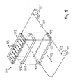
- Fig. 1 shows an electron beam unit 100 according to the prior art.
- the electron beam unit 100 is designed to irradiate irradiation material with a high dose rate in a planar manner.
- the material to be irradiated may be a material web 101, which is guided past the electron-beam unit 100 in a transport direction 102.
- the electron beam unit 100 can also be used to irradiate other irradiation material that is passed under the electron beam unit 100 at a certain speed.
- the electron beam unit 100 comprises a powerful cathode arrangement 103, which is designed to provide a sufficient number of free electrons for an areally extended irradiation of the irradiation material.
- the cathode assembly 103 includes a plurality of heating cathode wires 104 disposed in a plane above the web to be irradiated.
- the Schukathodendrähte 104 are preferably made of tungsten.
- the Schukathodendrähte 104 are arranged along the irradiation width 105 of the electron beam unit 100 parallel to each other at regular intervals, for example, at intervals of 6-10 cm.
- the irradiation width 105 of the electron beam unit 100 is usually in the range between about 30 cm and 3.5 m, depending on the width of the material to be irradiated.
- all Schukathodendrähte 104 are oriented parallel to each other in the transport direction 102.
- a constant voltage is applied to the heating cathode wires 104 so that a current of several amperes begins to flow through each of the heating cathode wires 104.
- Each of the heating cathode wires 104 is thus heated with a heating power of e.g. 150 W per wire heated.
- a heating power e.g. 150 W per wire heated.
- the electron beam unit 100 further includes one or more grid elements disposed below the cathode assembly 103.
- the grating elements are intended to subtract and distribute the electrons from the cathode assembly 103.
- Electron beam unit 100 shown comprises two grating elements 106 and 107. Between the cathode assembly 103 and the grating elements 106, 107, a grid voltage is applied. Thereby, the grating elements 106, 107 are set to a positive potential relative to the cathode assembly 103 to withdraw and distribute the electrons from the cathode assembly 103.
- the actual acceleration of the electrons takes place between the grating elements 106, 107 and the electron exit window 108.
- an acceleration voltage in the order of magnitude of a few 100 kV is applied between the grating elements 106, 107 and the electron exit window 108.
- the electrons are accelerated by this acceleration voltage to an energy of a few 100 keV, then pass through the electron exit window 108 into the open and act on the material web 101 to be irradiated.
- the electron exit window 108 of the electron beam unit 100 extends transversely to the transport direction 102 over the entire width of the web 101 to be irradiated.
- the width of the electron exit window 108 determines the irradiation width 105 of the electron beam unit 100.
- the length 109 of the electron exit window 108 is for example in the range of 5-30 cm.
- the electron exit window 108 comprises a thin film and a support structure on which the film rests.
- the film must be sufficiently thin so that the accelerated electrons can pass without significant energy losses.
- the film must be sufficiently stable so that it can withstand the pressure difference between the vacuum inside the electron beam unit 100 and the ambient pressure outside.
- a thin metal foil is used, for example a titanium foil having a thickness in the range between 5 ⁇ m and 30 ⁇ m.
- the metal foil rests on a support plate having a plurality of recesses through which the accelerated electrons can pass.
- the material web 101 to be irradiated is unwound from a development 110 in accordance with the arrow 111 and in the transport direction 102 with a given speed past the electron exit window 108.
- the irradiated material web 101 is wound on the winding 112 in the direction of the arrow 113.
- the material web 101 may be, for example, a web of paper, plastic or textile material.
- the electron beam irradiation can be used, for example, to harden printing ink, lacquer layers or other finishing layers applied to the material web 101.
- the dose rate with which the material web 101 is irradiated depends on the number and energy of the accelerated electrons and on the speed at which the material web 101 passes under the electron beam unit 100.
- a material web 101 is irradiated with electrons
- the plates to be irradiated are moved past the electron exit window 108 at a predetermined speed in a transport direction. In this way it is possible to harden on the plates applied paint layers, paint layers and other finishing layers.
- the plates may be, for example, wood panels or laminate panels, which are needed, for example, in the field of furniture production.
- Fig. 2A is the cathode assembly 103 of in Fig. 1 shown electron beam unit 100 shown in plan view. Evident are the along the irradiation width 105 parallel to each other at regular intervals arranged Bankkathodendrähte 104, which provide the required free electrons available. Typically, the heating cathode wires 104 are arranged along the entire irradiation width 105 of the electron beam unit at regular intervals of about 6-10 cm. In Fig. 2A the Schukathodendrähte 104 are aligned in the transport direction 102.
- the various heating cathode wires 104 of the cathode assembly 103 typically have small differences in thickness and structure resulting in emission differences with respect to lead the released electrons.
- the Schukathodendrähte 104 may have slightly different thicknesses.
- the Schukathodendrähte 104 may have grooves or peaks, so that the so-called peak effect occurs.
- the material tungsten tends to crystallize in partial areas, wherein the crystallized areas then also have an influence on the emission behavior.
- the electron emission over the irradiation width of the electron beam unit is not constant, but rather has variations caused by the mentioned differences in thickness and structure of the heating cathode wires 104.
- Fig. 2B the dose distribution associated with the cathode assembly 103 is plotted along the irradiation width 105 of the electron beam unit. On the vertical axis the dose is plotted in kGy, and on the right axis the position along the irradiation width 105 is plotted. It can be seen that the differences in thickness and structure of the Schukathodendrähte 104 lead to an inhomogeneous dose distribution along the irradiation width 105. The dose distribution may have burglary and elevations, so that there is usually no uniform wave pattern. This results in an uneven irradiation of the material to be irradiated.
- the Wienkathodendrumblete relative to the transport direction to be rotated by a predetermined angle, so that there is an oblique course of the Schukathodendrähte relative to the transport direction.
- a correspondingly formed cathode assembly 300 which comprises a plurality of Bankkathodendrumbleten 301 juxtaposed along the irradiation width of the electron beam unit.
- the Schukathodendrähte 301 are arranged in a plane above the web to be irradiated.
- the Schukathodendrähte 301 are arranged at regular intervals from each other along the irradiation width of the electron beam unit. All Walkerkathodendrähte 301 parallel to each other and are oriented in the same direction.
- Fig. 2A arranged all Walkerkathodendrähte 301 relative to the transport direction 302 by a predetermined angle ⁇ twisted.
- the angle ⁇ is for example in the range between about 2 ° and 60 °. Particularly preferred is a range for the angle ⁇ between 5 ° and 30 °.
- a predetermined point on a material web to be irradiated is considered, which is moved in the transport direction 302 under the cathode assembly 300.
- the predetermined point reaches position 303A.
- the point reaches position 303B, and a little later position 303C.
- the dose distributions acting at positions 303A, 303B, 303C on the material to be irradiated are in Fig. 3B shown.
- the irradiation dose is plotted in kGy, and along the right axis the position along the irradiation width of the electron emitter is plotted.
- the dose distribution 304A acts on the web.
- the predetermined point has moved to the position 303B, at this position 303B, the rightward dose distribution 304B acts on the web.
- the dose distribution 304B has shifted slightly to the right relative to the dose distribution 304A.
- the even further to the right shifted dose distribution 304C acts on the material web.
- the predetermined point on the material web is exposed to a dose distribution which shifts from left to right. On average, therefore, when passing through the electron beam unit, an average dose distribution 305 acts on each point of the material web Fig. 3B is shown as a dashed line.
- the dose fluctuations of the averaged dose distribution 305 are significantly lower than the dose fluctuations of the original dose distributions 304A, 304B, 304C.
- the averaging of the dose distributions 304A, 304B, 304C effected by the oblique course of the heating cathode wires 301 causes a reduction in the dose fluctuations along the irradiation width, so that the homogeneity of the electron irradiation can be markedly improved.
- the dose variations of the original dose distributions 304A, 304B and 304C are in the range of about 5.1-5.5%
- the average dose distribution 305 in the case shown has only a dose variation of 3.7%.
- the accuracy with which a desired irradiation dose can be applied therefore significantly improved by the oblique arrangement of Schukathodendrähte.
- FIG. 12 shows an electron beam unit 400, which is provided with a corresponding Fig. 3A trained cathode assembly 300 is equipped.
- the cathode assembly 300 includes a plurality of juxtaposed Bankkathodendrähten 301, which are arranged relative to the transport direction 302 each rotated by a predetermined angle ⁇ .
- the electron beam unit 400 further comprises a first grid element 401 and a second grid element 402, which are designed to draw off and distribute the free electrons generated by the heating cathode wires 301.
- the electrons are subjected to strong acceleration between the second grid element 402 and the electron exit window 403.
- the high energy electrons then pass through the electron exit window 403.
- the material web 404 is unwound from the unwind 405 and passed in the transport direction 302 under the electron exit window 403. There, the material web 404 is acted upon by high-energy electrons. The irradiated material web 404 is then wound up on the reel 406.
- the oblique orientation of the heating cathode wires 301 relative to the transport direction 302 ensures that the material web 404 is subjected to an averaged dose distribution when passing through the electron exit window 403. This improves the homogeneity of the electron irradiation.
- the electron beam unit 400 can also be used to irradiate other workpieces which are moved under a predetermined transport speed in a specific transport direction under the electron beam unit 400.
- the electron beam unit can be used for the irradiation of plates, which are guided in a certain transport direction under the electron beam unit.
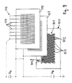
- Fig. 5 are the voltages required to accelerate the electrons in an overview.
- the Schukathodendrähte 301 of the cathode assembly 300 are arranged in a plane above the web to be irradiated. All Schukathodendrähte 301 of the cathode assembly 300 are parallel to each other and are oriented in the same direction. Relative to the transport direction 302, the Schukathodendrähte 301 are arranged rotated by the predetermined angle ⁇ , so that seen in the transport direction 302 results in an oblique course of Bankkathodendrähte 301.
- the heating cathode wires 301 When a current on the order of a few amperes flows through the heating cathode wires 301, the heating cathode wires 301 are strongly heated and a cloud of free electrons is formed around the heating cathode wires 301.
- a grid voltage U G on the order of a few hundred volts is applied.
- the grid voltage is poled so that the two grid elements 401, 402 are at a positive potential relative to the Schukathodendrähten 301.
- the grid voltage U G is designed to subtract the free electrons from the Bankkathodendrähten 301, distribute and accelerate to the grid elements 401, 402 towards.
- the two grid elements 401 and 402 are at the same potential.
- the acceleration voltage U B is applied, which moves in the order of about 60 kV to several hundred kV.
- the acceleration voltage U B is polarized such that the electron exit window 403 is at a positive potential relative to the grid elements 401, 402.
- the electron exit window 403 is part of the housing of the electron beam unit 400 and is therefore grounded.
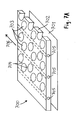
- Fig. 5 is in the representation of the electron exit window 403 and the structure of the support structure 500 drawn with.
- the support structure 500 is formed as a perforated plate and includes a plurality of openings 501 through which the accelerated electrons can pass.
- a plurality of cooling channels 502 can be seen, which extend within the support structure from the front to the back of the electron exit window 403. The direction in which the in Fig. 5 shown cooling channels 502, corresponding to the transport direction 302 of the material web 404th
- FIGs. 6A-6C three embodiments of cathode assemblies are shown, each having obliquely arranged to the transport direction Schukathodendrähte.
- cathode assembly 600 includes a plurality of Bankkathodendrumbleten 601, which are arranged obliquely to the transport direction 602.
- the heating cathode wires 601 are arranged such that the end point 603 of a heating cathode wire as viewed in the transporting direction 602 lies behind the starting point 604 of an adjacent heating cathode wire, as shown in FIG Fig. 6A is illustrated by the dashed lines 605.
- This arrangement of the Bankkathodendrähte 601 is achieved that each point along the in Fig. 6A also shown irradiation width 606 is covered by exactly one Bankkathodendraht 601. This achieves a particularly uniform charging of the surface radiator with electrons.
- FIG. 6B another embodiment of a cathode assembly 607 is shown.
- the cathode arrangement 607 comprises a plurality of heating cathode wires 608, which are arranged parallel to one another and at an angle to the transport direction 609.
- the arrangement of the Schukathodendrumblete 608 is chosen so that the end portion 610 of a Schukathodendrahts in the transport direction 609 as viewed overlaps each with the beginning portion 611 of an adjacent Schukathodendrahts.
- FIG. 6C another embodiment of a cathode assembly 613 is shown, which in turn comprises a plurality of Bankkathodendrumbleten 614, which are arranged relative to the transport direction 615 obliquely.
- a Bankkathodendraht 614 seen in the transport direction 615 is formed overlapping with the adjacent Schukathodendraht 614.
- the heating cathode wires 614 are arranged so that the end point 616 of a Schukathodendrahts seen in the direction of transport 615 is respectively behind the starting point 617 of the next Schukathodendrahts 614, as shown in FIG Fig.
- This second aspect is a stand-alone measure that can be implemented independently of the previously described oblique arrangement of the Schukathodendrähte.
- this second aspect can also be combined in an advantageous manner with the first aspect, namely the oblique arrangement of Schukathodendrähte.
- FIG. 7A an electron exit window 700 according to the prior art is shown.
- the electron exit window 700 comprises a metal foil 701 and a support structure 702, on which the metal foil 701 rests.
- the metal foil 701 and the support structure 702 extend over the entire irradiation width of the electron beam unit.
- Inside the electron beam unit there is a vacuum, while outside the electron beam unit the normal atmospheric pressure prevails.
- the metal foil 701 abuts against the outside of the support structure 702. Due to the pressure difference between the vacuum inside the electron beam unit and the ambient pressure outside of the Electron beam unit, the metal foil 701 is pressed from the outside against the support structure 702.
- the metal foil 701 must be sufficiently stable in order to be able to withstand this pressure difference.
- the metal foil 701 must be formed sufficiently thin, so that the accelerated electrons are only slightly weakened when passing through the metal foil 701.
- the metal foil 701 preferably has a thickness in the range between, for example, 5 ⁇ m and 20 ⁇ m.
- a thin titanium foil having a thickness in the range between 5 ⁇ m and 20 ⁇ m can be used.
- the support structure 702 is typically formed in the manner of a perforated plate and includes a plurality of openings 703 and webs 704. Through the openings 703 of the support structure 702, the accelerated electrons can pass through unhindered and are then weakened only by the metal foil 701. In the area of the webs 704, however, the accelerated electrons are absorbed. The webs 704 are necessary in order to obtain a sufficiently high stability of the support structure 702 over the entire irradiation width.
- the support structure 702 absorbs a variety of high energy electrons. As a result, the support structure 702 heats up strongly.
- a plurality of cooling channels 705 are provided within the support structure 702. Coolant is pumped through these cooling passages 705, and thus the heat caused by the absorbed electrons is removed.
- the cooling channels 705 extend in the longitudinal direction. The cooling channels 705 are thus aligned in the transport direction 706 of the material to be irradiated.
- Fig. 7B the electron exit window 700 is shown in plan view, wherein the support structure 702 can be seen.
- the accelerated electrons can pass through the openings 703 of the support structure 702.
- Fig. 7C shows the dose distribution 707 of the irradiation dose, which is delivered along the irradiation width of the electron beam unit to the material to be irradiated.
- the position along the irradiation width of the electron beam unit is plotted, and on the vertical axis the irradiation dose is plotted in kGy.
- the dose distribution 707 has characteristic subsidences 709 at the locations 708 where the cooling channels 705 run. At points 708 where the cooling channels 705 extend, the accelerated electrons can not penetrate the support structure 702. There arise therefore characteristic shadowing, which can be seen in the dose distribution 707 as subsidence 709. Because of these shades occurring along the irradiation width, the dose applied to the irradiation material becomes inhomogeneous and thus inaccurate.
- the cooling channels are oriented rotated relative to the transport direction of the irradiation by a predetermined angle, so that there is an oblique course of the cooling channels relative to the transport direction.
- FIG. 8 an electron exit window 800 is shown with a correspondingly formed support structure 801.
- the support structure 801 has a plurality of openings 802 through which the accelerated electrons can pass.
- the support structure 801 has a multiplicity of cooling channels 803 arranged parallel to one another, which are arranged next to one another along the irradiation width of the electron beam unit.
- the cooling channels 803 are arranged relative to the transport direction 804 rotated by a predetermined angle ⁇ .
- the cooling channels 803 therefore run obliquely to the transport direction 804.
- the angle ⁇ can be, for example, in the range between approximately 2 ° and 60 °. Particularly preferred is a range for the angle ⁇ between 5 ° and 30 °.
- a first dose distribution acts on the point under consideration. If the point then reaches a second position 806 at a later time, then a dose distribution shifted to the left by a distance acts on the point under consideration. During the irradiation period, the dose distribution 707 with the reductions 709 thus shifts continuously from right to left, so that in total an average dose distribution acts on the irradiation material. Through this averaging process, the shading caused by the cooling channels 803 is averaged out.
- Fig. 9 are the voltages required to accelerate the electrons in an overview.
- the Schukathodendrähte 104 of the cathode assembly 103 are arranged in a plane above the web to be irradiated.
- the Schukathodendrähte 104 of the cathode assembly 103 are arranged parallel to each other.
- the heating cathode wires 104 are oriented in the transporting direction 804.
- a grid voltage U G is applied in the order of a few hundred volts.
- the grid voltage U G serves to draw the free electrons from the Bankkathodendrähten 104, distribute and accelerate to the grid elements 106, 107 out.
- the grid voltage is poled so that the two grid elements 106, 107 are at a positive potential relative to the Bankkathodendrähten 104.
- the acceleration voltage U B which is on the order of about 60 kV to several hundred kV, is applied between the grid elements 106, 107 and the electron exit window 800.
- the acceleration voltage U B is polarized such that the electron exit window 800 is at a positive potential relative to the grid elements 106, 107.
- the acceleration voltage U B is used to accelerate the electrons on the path between the second grid element 107 and the electron exit window 800.
- the electron exit window 800 is part of the housing of the electron beam unit 100 and is therefore grounded.
- FIG. 9 In the illustration of the electron exit window 800, the structure of the support structure 801 is also shown.
- the support structure 801 is formed as a perforated plate and includes a plurality of openings 802 through which the accelerated electrons can pass.
- a plurality of cooling channels 803 can be seen, which extend within the support structure 801 from the front to the back of the electron exit window 800. It can be seen that the cooling channels 803 are arranged rotated relative to the transport direction 804 by an angle ⁇ and thus extend obliquely to the transport direction 804.
- Supporting structure 1000 shown includes a plurality of cooling channels 1001, which are arranged obliquely to the transport direction 1002.
- the cooling channels 1001 are arranged such that the end point 1003 of a cooling channel, viewed in the transporting direction 1002, lies in each case behind the starting point 1004 of an adjacent cooling channel, as shown in FIG Fig. 10A is illustrated by the dashed lines.
- This arrangement of the cooling channels 1001 ensures that each point along the in Fig. 10A also shown irradiation width 1005 is covered by exactly one cooling channel 1001. As a result, the shadowing caused by the cooling channels is uniformly distributed along the irradiation width 1005.
- FIG. 10B another embodiment of a support structure 1006 is shown.
- the support structure 1006 comprises a plurality of cooling channels 1007, which are arranged parallel to one another and at an angle to the transport direction 1008.
- the arrangement of the cooling channels 1007 is chosen so that the end portion 1009 of a cooling channel, viewed in the transport direction 1008, overlaps each with the starting portion 1010 of an adjacent cooling channel.
- the shadings caused by the cooling channels are distributed uniformly along the irradiation width 1011.
- a further embodiment of a support structure 1012 is shown, which in turn comprises a plurality of cooling channels 1013, which are arranged obliquely relative to the transport direction 1014.
- a cooling channel 1013 seen in the transport direction 1014, is formed overlapping with the adjacent cooling channel 1013.
- the cooling channels 1013 are arranged such that the end point 1015 of a cooling channel, viewed in the transport direction 1014, lies in each case behind the starting point 1016 of the next but one cooling channel, as shown in FIG Fig. 10C is illustrated by the dashed lines.
- the shadings caused by the cooling channels are distributed uniformly along the irradiation width 1017.
- the cooling channels are oriented rotated relative to the transport direction of the irradiation by a predetermined angle, so that there is an oblique course of the cooling channels relative to the transport direction.
- the second aspect is a standalone measure that can be implemented on its own, independently of the first aspect.
- the Schuhodendrumblete are arranged rotated relative to the transport direction by a predetermined angle, so that there is an oblique course of the Schukathodendrumblete relative to the transport direction. Also in this first aspect is an independent measure that can be implemented independently of the second aspect alone.
- the Wienkathodendrähte are arranged rotated relative to the transport direction by a predetermined first angle, and according to the second aspect, the cooling channels are oriented relative to the transport direction of the irradiated by a predetermined second angle.
Landscapes
- Electron Sources, Ion Sources (AREA)
- Physical Or Chemical Processes And Apparatus (AREA)
Applications Claiming Priority (1)
| Application Number | Priority Date | Filing Date | Title |
|---|---|---|---|
| DE102014001344.8A DE102014001344B4 (de) | 2014-02-02 | 2014-02-02 | Elektronenstrahleinheit mit schräg zur Transportrichtung ausgerichteten Heizkathodendrähten sowie Verfahren zur Bestrahlung |
Related Child Applications (1)
| Application Number | Title | Priority Date | Filing Date |
|---|---|---|---|
| EP23163846.1A Previously-Filed-Application EP4224044A1 (fr) | 2014-02-07 | 2015-02-06 | Soupape à tiroir |
Publications (1)
| Publication Number | Publication Date |
|---|---|
| EP2903016A1 true EP2903016A1 (fr) | 2015-08-05 |
Family
ID=52434512
Family Applications (1)
| Application Number | Title | Priority Date | Filing Date |
|---|---|---|---|
| EP15000241.8A Withdrawn EP2903016A1 (fr) | 2014-02-02 | 2015-01-27 | Unité de rayonnement d'électrons ayant des fils de cathode à chauffage direct inclinés par rapport au sens de transport |
Country Status (2)
| Country | Link |
|---|---|
| EP (1) | EP2903016A1 (fr) |
| DE (1) | DE102014001344B4 (fr) |
Families Citing this family (3)
| Publication number | Priority date | Publication date | Assignee | Title |
|---|---|---|---|---|
| DE102019118657B4 (de) | 2019-07-10 | 2024-07-25 | Vitalij Lissotschenko | Vorrichtung zur Erzeugung einer Elektronenstrahlung sowie 3D-Druck-Vorrichtung |
| DE102019124684A1 (de) | 2019-09-13 | 2021-03-18 | Vitalij Lissotschenko | Vorrichtung zur Erzeugung einer Elektronenstrahlung sowie 3D-Druck-Vorrichtung |
| DE102024128457A1 (de) * | 2024-10-01 | 2026-04-02 | Fraunhofer-Gesellschaft zur Förderung der angewandten Forschung eingetragener Verein | Vorrichtung zum Beaufschlagen von Fluiden und Innenwandungen von Hohlkörpern mit beschleunigten Elektronen |
Citations (6)
| Publication number | Priority date | Publication date | Assignee | Title |
|---|---|---|---|---|
| JPS5920957A (ja) * | 1982-07-26 | 1984-02-02 | Nisshin Haiboruteeji Kk | 電子線照射装置 |
| JPH09292500A (ja) * | 1996-04-25 | 1997-11-11 | Nissin High Voltage Co Ltd | 電子線照射装置の窓箔冷却構造 |
| JPH1172600A (ja) * | 1997-08-28 | 1999-03-16 | Nissin High Voltage Co Ltd | 電子線照射装置 |
| JP2002243899A (ja) * | 2001-02-19 | 2002-08-28 | Nissin High Voltage Co Ltd | 電子線照射装置 |
| JP2008237380A (ja) * | 2007-03-26 | 2008-10-09 | Shibuya Kogyo Co Ltd | 電子線殺菌装置 |
| DE102009057357A1 (de) * | 2009-12-07 | 2011-06-09 | Electron Crosslinking Ab | Elektronenstrahleinheit zum Aufprägen eines Intensitätsprofils |
Family Cites Families (8)
| Publication number | Priority date | Publication date | Assignee | Title |
|---|---|---|---|---|
| US5414267A (en) * | 1993-05-26 | 1995-05-09 | American International Technologies, Inc. | Electron beam array for surface treatment |
| US5962995A (en) * | 1997-01-02 | 1999-10-05 | Applied Advanced Technologies, Inc. | Electron beam accelerator |
| US6545398B1 (en) * | 1998-12-10 | 2003-04-08 | Advanced Electron Beams, Inc. | Electron accelerator having a wide electron beam that extends further out and is wider than the outer periphery of the device |
| US6239543B1 (en) * | 1999-08-23 | 2001-05-29 | American International Technologies, Inc. | Electron beam plasma formation for surface chemistry |
| JP2002182000A (ja) * | 2000-12-14 | 2002-06-26 | Ushio Inc | 電子ビーム処理装置 |
| US6750461B2 (en) * | 2001-10-03 | 2004-06-15 | Si Diamond Technology, Inc. | Large area electron source |
| WO2003067636A1 (fr) * | 2002-01-22 | 2003-08-14 | Tokyo Electron Limited | Dispositif et procede de traitement de surface |
| JP2005195469A (ja) * | 2004-01-07 | 2005-07-21 | Toyo Ink Mfg Co Ltd | 電子線照射装置および電子線照射方法 |
-
2014
- 2014-02-02 DE DE102014001344.8A patent/DE102014001344B4/de active Active
-
2015
- 2015-01-27 EP EP15000241.8A patent/EP2903016A1/fr not_active Withdrawn
Patent Citations (6)
| Publication number | Priority date | Publication date | Assignee | Title |
|---|---|---|---|---|
| JPS5920957A (ja) * | 1982-07-26 | 1984-02-02 | Nisshin Haiboruteeji Kk | 電子線照射装置 |
| JPH09292500A (ja) * | 1996-04-25 | 1997-11-11 | Nissin High Voltage Co Ltd | 電子線照射装置の窓箔冷却構造 |
| JPH1172600A (ja) * | 1997-08-28 | 1999-03-16 | Nissin High Voltage Co Ltd | 電子線照射装置 |
| JP2002243899A (ja) * | 2001-02-19 | 2002-08-28 | Nissin High Voltage Co Ltd | 電子線照射装置 |
| JP2008237380A (ja) * | 2007-03-26 | 2008-10-09 | Shibuya Kogyo Co Ltd | 電子線殺菌装置 |
| DE102009057357A1 (de) * | 2009-12-07 | 2011-06-09 | Electron Crosslinking Ab | Elektronenstrahleinheit zum Aufprägen eines Intensitätsprofils |
Also Published As
| Publication number | Publication date |
|---|---|
| DE102014001344B4 (de) | 2015-08-20 |
| DE102014001344A1 (de) | 2015-08-06 |
Similar Documents
| Publication | Publication Date | Title |
|---|---|---|
| DE102009040031B4 (de) | Lasergetriebene Teilchenstrahl-Bestrahlungsvorrichtung sowie -Verfahren | |
| DE112005002171B4 (de) | Teilchenstrahl-Bestrahlungsverfahren und dafür verwendete Teilchenstrahl-Bestrahlungsvorrichtung | |
| DE69931502T2 (de) | Kollimator für strahlentherapiegerät | |
| DE3105359A1 (de) | Ionenimplantationssystem, verfahren zur strahlablenkung zwecks gleichfoermiger bestrahlung, ablenksystem und verfahren zur erzeugung einer nichtlinearen wellenform | |
| DE102008023350A1 (de) | Teilchenbestrahlungsvorrichtung, Teilchenbestrahlungsverfahren und Teilchenstrahlbehandlungssystem | |
| WO2015058971A1 (fr) | Dispositif de génération d'électrons accélérés | |
| DE69108367T2 (de) | Vorrichtung zum Vakuumbeschichten mittels Bogenentladung. | |
| DE102014001344B4 (de) | Elektronenstrahleinheit mit schräg zur Transportrichtung ausgerichteten Heizkathodendrähten sowie Verfahren zur Bestrahlung | |
| EP2510535B1 (fr) | Système de déviation des faisceaux électroniques | |
| DE1808719B2 (de) | Verfahren und Vorrichtung zusn Be handeln von Oberflachen, insbesondere zum Harten von Lackschichten, durch Be strahlung mit Ladungstragerstrahlen | |
| DE19518717C2 (de) | Vorrichtung zum Bestrahlen von Oberflächen mit Elektronen | |
| DE102012211285B3 (de) | Röntgenröhre und Verfahren zum Betrieb einer Röntgenröhre | |
| EP2903017A2 (fr) | Structure d'appui doté de canaux de refroidissement s'étendant de manière inclinée pour une fenêtre de sortie d'électrons | |
| DE102011018613B4 (de) | Bestrahlungsanlage mit mehreren einstellbaren Messbereichen einer Strahlmonitoreinrichtung und Steuerverfahren für diese Bestrahlungsanlage | |
| DE3442243C2 (fr) | ||
| CH616017A5 (fr) | ||
| DE4102983A1 (de) | Oberflaechenstruktur einer walze sowie verfahren und vorrichtung zur erzeugung der oberflaechenstruktur | |
| DE2317748A1 (de) | Ablenkvorrichtung zur umformung eines schmalen strahlenbuendels energiereicher elektronen in ein breites strahlenbuendel gewuenschter querschnittsflaeche | |
| DE2306567C3 (de) | Bestrahlungsanlage mit einem Elektronenbeschleuniger | |
| DE3816946A1 (de) | Elektronenstrahl-bestrahlungseinrichtung | |
| DE102015209825A1 (de) | Vorrichtung zum Teilen einer laufenden Materialbahn in Transportrichtung | |
| DE3146826A1 (de) | Vorrichtung zur oberflaechenbehandlung von folienartigen werkstoffen mit koronaentladungen | |
| DE3407320C1 (de) | Verfahren und Anlage zur Elektronenstrahlhärtung | |
| DE102009061727B4 (de) | Elektronenstrahleinheit mit Strahlfeldbegrenzung und Verfahren dazu | |
| DE1211727B (de) | Einrichtung zur Regelung der Ablenkung des Elektronenstrahles eines Teilchenbeschleunigers in horizontaler Bauweise |
Legal Events
| Date | Code | Title | Description |
|---|---|---|---|
| PUAI | Public reference made under article 153(3) epc to a published international application that has entered the european phase |
Free format text: ORIGINAL CODE: 0009012 |
|
| 17P | Request for examination filed |
Effective date: 20150127 |
|
| AK | Designated contracting states |
Kind code of ref document: A1 Designated state(s): AL AT BE BG CH CY CZ DE DK EE ES FI FR GB GR HR HU IE IS IT LI LT LU LV MC MK MT NL NO PL PT RO RS SE SI SK SM TR |
|
| AX | Request for extension of the european patent |
Extension state: BA ME |
|
| STAA | Information on the status of an ep patent application or granted ep patent |
Free format text: STATUS: THE APPLICATION IS DEEMED TO BE WITHDRAWN |
|
| 18D | Application deemed to be withdrawn |
Effective date: 20160206 |