EP2903261A1 - Appareil et procédé pour détecter un événement à partir d'une pluralité d'images photographiées - Google Patents
Appareil et procédé pour détecter un événement à partir d'une pluralité d'images photographiées Download PDFInfo
- Publication number
- EP2903261A1 EP2903261A1 EP13840942.0A EP13840942A EP2903261A1 EP 2903261 A1 EP2903261 A1 EP 2903261A1 EP 13840942 A EP13840942 A EP 13840942A EP 2903261 A1 EP2903261 A1 EP 2903261A1
- Authority
- EP
- European Patent Office
- Prior art keywords
- event
- interest
- rule
- individual
- event rule
- Prior art date
- Legal status (The legal status is an assumption and is not a legal conclusion. Google has not performed a legal analysis and makes no representation as to the accuracy of the status listed.)
- Granted
Links
Images


Classifications
-
- G—PHYSICS
- G06—COMPUTING OR CALCULATING; COUNTING
- G06T—IMAGE DATA PROCESSING OR GENERATION, IN GENERAL
- G06T7/00—Image analysis
- G06T7/20—Analysis of motion
- G06T7/292—Multi-camera tracking
-
- G—PHYSICS
- G06—COMPUTING OR CALCULATING; COUNTING
- G06T—IMAGE DATA PROCESSING OR GENERATION, IN GENERAL
- G06T7/00—Image analysis
- G06T7/20—Analysis of motion
-
- G—PHYSICS
- G06—COMPUTING OR CALCULATING; COUNTING
- G06T—IMAGE DATA PROCESSING OR GENERATION, IN GENERAL
- G06T7/00—Image analysis
- G06T7/20—Analysis of motion
- G06T7/254—Analysis of motion involving subtraction of images
-
- G—PHYSICS
- G06—COMPUTING OR CALCULATING; COUNTING
- G06V—IMAGE OR VIDEO RECOGNITION OR UNDERSTANDING
- G06V20/00—Scenes; Scene-specific elements
- G06V20/50—Context or environment of the image
- G06V20/52—Surveillance or monitoring of activities, e.g. for recognising suspicious objects
-
- H—ELECTRICITY
- H04—ELECTRIC COMMUNICATION TECHNIQUE
- H04N—PICTORIAL COMMUNICATION, e.g. TELEVISION
- H04N7/00—Television systems
- H04N7/18—Closed-circuit television [CCTV] systems, i.e. systems in which the video signal is not broadcast
-
- H—ELECTRICITY
- H04—ELECTRIC COMMUNICATION TECHNIQUE
- H04N—PICTORIAL COMMUNICATION, e.g. TELEVISION
- H04N7/00—Television systems
- H04N7/18—Closed-circuit television [CCTV] systems, i.e. systems in which the video signal is not broadcast
- H04N7/181—Closed-circuit television [CCTV] systems, i.e. systems in which the video signal is not broadcast for receiving images from a plurality of remote sources
-
- G—PHYSICS
- G06—COMPUTING OR CALCULATING; COUNTING
- G06T—IMAGE DATA PROCESSING OR GENERATION, IN GENERAL
- G06T2207/00—Indexing scheme for image analysis or image enhancement
- G06T2207/30—Subject of image; Context of image processing
- G06T2207/30232—Surveillance
-
- G—PHYSICS
- G06—COMPUTING OR CALCULATING; COUNTING
- G06T—IMAGE DATA PROCESSING OR GENERATION, IN GENERAL
- G06T2210/00—Indexing scheme for image generation or computer graphics
- G06T2210/12—Bounding box
-
- G—PHYSICS
- G08—SIGNALLING
- G08B—SIGNALLING SYSTEMS, e.g. PERSONAL CALLING SYSTEMS; ORDER TELEGRAPHS; ALARM SYSTEMS
- G08B13/00—Burglar, theft or intruder alarms
- G08B13/18—Actuation by interference with heat, light, or radiation of shorter wavelength; Actuation by intruding sources of heat, light, or radiation of shorter wavelength
- G08B13/189—Actuation by interference with heat, light, or radiation of shorter wavelength; Actuation by intruding sources of heat, light, or radiation of shorter wavelength using passive radiation detection systems
- G08B13/194—Actuation by interference with heat, light, or radiation of shorter wavelength; Actuation by intruding sources of heat, light, or radiation of shorter wavelength using passive radiation detection systems using image scanning and comparing systems
- G08B13/196—Actuation by interference with heat, light, or radiation of shorter wavelength; Actuation by intruding sources of heat, light, or radiation of shorter wavelength using passive radiation detection systems using image scanning and comparing systems using television cameras
- G08B13/19639—Details of the system layout
- G08B13/19641—Multiple cameras having overlapping views on a single scene
Definitions
- the present disclosure in one or more embodiments relates to an apparatus and a method for detecting an event from a plurality of captured images. More particularly, the present disclosure relates to an apparatus and a method for detecting a single event from multiple captured images, by converting an event rule for a synthesized image from the multiple captured images through conversion functions corresponding to the coordinate systems of multiple cameras into individual event rules as a basis for determining multiple individual events, and identifying the determined multiple individual events through the predetermined conversion functions as a single event.
- a typical video security system sets an event rule for each of installed cameras and the event rule is used as a basis for detecting each and every event and to produce multiple redundant event detections even from a a single object that actually causes those events. Such unnecessary detections increase processing burden and time required for identifying numerous event occurrences as an actually same event.
- the present disclosure provides an apparatus and a method for detecting a single event from multiple captured images by converting an event rule for a synthesized image from the multiple captured images through conversion functions corresponding to the coordinate systems of the multiple cameras into individual event rules as a basis for determining multiple individual events, and detecting or identifying the determined multiple individual events through the predetermined conversion functions as the single event.
- an apparatus for generating an individual event rule comprises an image receiver, an image synthesis unit, an event rule acquisition unit, an individual event rule generator and a rule transmitter.
- the image receiver is configured to receive multiple captured images from multiple cameras.
- the image synthesis unit is configured to synthesize the multiple captured images into a main image through conversion functions corresponding to coordinate systems of the multiple cameras.
- the event rule acquisition unit is configured to acquire an event rule for the main image.
- the individual event rule generator is configured to convert the event rule through the conversion functions into individual event rules corresponding respectively to the cameras.
- the rule transmitter is configured to transmit the individual event rules for identifying a single event.
- an event detecting apparatus includes an image receiver, a rule receiver, an object-of-interest extractor, an individual event determiner, an event identifier and an event output unit.
- the image receiver is configured to receive multiple captured images from multiple cameras.
- the rule receiver is configured to receive an event rule as a basis for determining the presence or absence of a predetermined event from a synthesized image of the multiple captured images and individual event rules which are converted from the event rule through conversion functions corresponding to coordinate systems of the multiple cameras.
- the object-of-interest extractor is configured to extract an object-of-interest from the captured images.
- the individual event determiner is configured to determine whether trace information of the object-of-interest corresponds to individual events based on the individual event rules.
- the event identifier is configured to generate inversely converted trace information from the trace information of the object-of-interest through the conversion functions, determine whether multiple pieces of the inversely converted trace information comply with the event rule, and when the multiple pieces of the inversely converted trace information comply with the event rule, identify the object-of-interest as a single event.
- the event output unit is configured to generate output information according to the identified single event.
- a method for generating an individual event rule includes receiving multiple captured images from multiple cameras; synthesizing the multiple captured images through conversion functions corresponding to coordinate systems of the multiple cameras into a main image; acquiring an event rule for the main image; generating individual event rules by converting the event rule through the conversion functions into the individual event rules corresponding respectively to the cameras; and transmitting the individual event rules for identifying a single event.
- an event detecting method includes receiving multiple captured images from multiple cameras; receiving an event rule as a basis for determining the presence or absence of a predetermined event of a synthesized image of the multiple captured images and individual event rules which are converted from the event rule through conversion functions corresponding to coordinate systems of the multiple cameras; extracting an object-of-interest from the captured images; determining an individual event by determining whether trace information of the object-of-interest corresponds to individual events based on the individual event rules; performing event identification, including generating an inversely converted trace information from the trace information of the object-of-interest through the conversion functions, determining if multiple pieces of the inversely converted trace information comply with the event rule, and if comply with the event rule, identifying the object-of-interest as a single event; and performing event output by generating output information according to the identified single event.
- a single event is detected from multiple captured images, by converting an event rule for a synthesized image from the multiple captured images through conversion functions corresponding to the coordinate systems of multiple cameras into individual event rules as a basis for determining multiple individual events, and identifying the determined multiple individual events through the predetermined conversion functions as the single event. Therefore, multiple event rules are not necessary, repeated events are not detected, and thus events can be easily stored, identified and managed. In addition, the number of detecting devices can be reduced by setting a single event rule for a plurality of cameras.
- first, second, A, B, (a), and (b) are used. These are solely for the purpose of differentiating one component from another, and one of ordinary skill would understand that the terms are not to imply or suggest the substances, the order or sequence of the components. If a component is described as 'connected', 'coupled', or 'linked' to another component, one of ordinary skill in the art would understand that the components are not necessarily directly 'connected', 'coupled', or 'linked' but also are indirectly 'connected', 'coupled', or 'linked' via a third component.
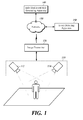
- FIG. 1 is a schematic block diagram of an event detecting system according to at least one embodiment of the present disclosure.
- the event detecting system includes an image capture apparatus 110, an image transmitter 120, a network 130, an individual event rule generating apparatus 140 and an event detecting apparatus 150.
- the image capture apparatus 110 includes a first camera 112 and a second camera 114.
- the image capture apparatus 110 is a device for capturing images.
- the image capture apparatus 110 includes at least one camera, for example, a closed circuit television (CCTV) camera, a security camera, etc. capable of capturing images in order to monitor an object as to whether some events such as movement, intrusion, deviation, theft and being left unattended, are occurred with respect to the object.
- the captured image includes a plurality of frames captured by the multiple cameras 112 and 114.
- the image capture apparatus 110 includes the multiple cameras such as the first camera 112 and the second camera 114 for capturing all or a part of an area of the same location in different directions.
- the first camera 112 is able to be arranged to capture the left side of the playground and the second camera 114 is able to be arranged to capture the right side of the playground.
- the image transmitter 120 transmits the images captured by the image capture apparatus 110 including the multiple cameras to the individual event rule generating apparatus 140 and to the event rule detecting apparatus 150.
- the image transmitter 120 is illustrated as exchanging data of images and rules via the network 130, at least one embodiment of the present disclosure is not limited thereto, and the image transmitter 120 transmits and receives data via a network 130.
- the network 130 is capable of transmitting and receiving the data of the images and rules, and includes least one of local area communication network and a communication network corresponding to a communication base station installed by an operator.
- the individual event rule generating apparatus 140 receives the captured images from the image transmitter 120, generates a main image that is synthesized from the captured images by using predetermined conversion functions, and sets a pre-generated event rule for the main image. In addition, the individual event rule generating apparatus 140 processes the main image causing the event rule through the predetermined conversion function to generate a plurality of individual rule images. And the individual event rule generating apparatus 140 transmits both the event rule for the main image and individual event rules for the individual rule images to the event detecting apparatus 150.
- the individual event rule generating apparatus 140 synthesizes the multiple captured images and generates a single main image through the predetermined conversion functions corresponding to coordinate systems of the cameras.
- the predetermined conversion functions are functions of a scheme such as homography and calibration for correcting a distorted image using coordinates system.
- the individual event rule generating apparatus 140 acquires an event rule for the synthesized main image.
- the event rule serves as a rule that is set up through a manager's manipulation with respect to the synthesized main image and it means conditional information for recognizing the occurrence of an event if there is an object-of-interest moving through a region-of-interest generated through a manager's setting command such as interface manipulation or coordinate input. A detailed description of the event rule will be given with reference to FIG. 2 .
- the individual event rule generating apparatus 140 converts the event rule for the main image into individual event rules corresponding respectively to the multiple cameras through the predetermined conversion functions corresponding to the coordinate systems of the cameras. For example, upon obtaining an event rule set to a circular shape of region-of-interest for the main image, the individual event rule generating apparatus 140 converts the left half circle of the region-of-interest into a first individual event rule through a conversion function corresponding to the first camera 112 and converts the right half circle of the region-of-interest into a second individual event rule through a conversion function corresponding to the second camera 114.
- the individual event rule generating apparatus 140 converts ' ⁇ ' or the left part of the T-shaped region-of-interest to the first individual event rule through the conversion function corresponding to the first camera 112 and converts ' ⁇ ' or the right part of the T-shaped region-of-interest to the second individual event rule through the conversion function corresponding to the second camera 114.
- the event detecting apparatus 150 is adapted to receive the event rule and the individual event rules from the individual event rule generating apparatus 140 and detect an object-of-interest corresponding to an event.
- the event detecting apparatus 150 is connected to the image transmitter 120 to receive the captured images. It receives the event rule and individual event rules from the individual event rule generating apparatus 140.
- the event rule indicates a rule for the main image generated from the individual event rule generating apparatus 140 through a predetermined conversion function and the individual event rules indicate rules corresponding respectively to the cameras, which are converted through predetermined conversion functions corresponding to coordinate systems of the cameras.
- the event detecting apparatus 150 compares prestored background images with the captured images, determines their difference as a moving object-of-interest, and extracts trace information of the object-of-interest.
- the trace information is desirably expressed by a coordinate value, e.g., (x, y) at which the object-of-interest is located, at least one embodiment of the present disclosure is not necessarily restricted thereto.
- the trace information is a distance value from a predetermined starting point.
- the prestored background images are precaptured by multiple cameras and they represent images indicating a still background for a predetermined time rather than the moving object-of-interest in the captured images.
- the event detecting apparatus 150 is responsive to a change in the sign value of the trace information of the object-on-interest for identifying identifies the object-of-interest as an individual event passing through a region-of-interest according to the individual event rules.
- the individual event is an individual event in which the object-of-interest passes through a boundary line in the region-of-interest according to the individual event rules, at least one embodiment of the present disclosure is not necessarily limited thereto, and the individual event rule is an individual event of a trespassing on or an escape from the boundary region in the region-of-interest.
- the event detecting apparatus 150 generates inversely converted trace information by using a predetermined conversion function from the trace information of the object-of-interest determined as the individual event. If multiple pieces of inversely converted trace information corresponding respectively to the multiple cameras comply with the event rule, the event detecting apparatus 150 identifies the inversely converted trace information as a single event. From the trace information of the object-of-interest identified as the individual event, the inversely converted trace information is generated through a conversion function such as homography and calibration for correcting a distorted image by using a coordinate system of a camera.
- a conversion function such as homography and calibration for correcting a distorted image by using a coordinate system of a camera.
- the event detecting apparatus 150 performs the operation of monitoring an event by displaying and/or alerting output information of the detected event.
- the event detecting apparatus 150 calculates statistical information of an event by using the output information for the detected event.
- the statistical information refers to information calculated through determining the number of occurrences of events such as a trespassing on, intrusion into and escape from the region-of-interest.
- FIG. 2 is a schematic block diagram of an individual event rule generator according to at least one embodiment of the present disclosure.
- the individual event rule generating apparatus 140 includes an image receiver 210, an image synthesizer 222, an event rule acquisition unit 224, an individual event rule generator 226, an event rule generator 230 and a rule transmitter 240.
- the image receiver 210 is connected to the image transmitter 120 and receives captured images.
- the captured images refer to images captured by a plurality of cameras included in the image capture apparatus 110.
- a captured image is, but is not always limited to, one frame or is an image composed of a combination of a plurality of frames.
- the image synthesizer 222 generates a single main image by synthesizing the multiple captured images through predetermined conversion functions.
- the image synthesizer 222 synthesizes the multiple captured images by using predetermined conversion functions corresponding to coordinate systems of the cameras to generate the single main image.
- the predetermined conversion functions are functions using a homography and calibration scheme for correcting a distorted image by using the coordinate systems. For example, when the first camera 112 and the second camera 114 capture the images of the same area in different directions, the image synthesizer 222 receives from the first camera 112 a captured image with a pedestrian located in the left side of the image, and receives from the second camera 114 a captured image with the pedestrian located in the right side of the image so as to generate a main image in which the passerby is centrally located through the predetermined conversion function.
- the event rule acquisition unit 224 acquires an event rule for the main image from the event rule generator 230.
- the event rule is a rule that is set up through the manager's manipulation with respect to the synthesized main image from the captured images and it means conditional information for recognizing the occurrence of an event if there is an object-of-interest moving through a region-of-interest generated through a manager's setting command such as interface manipulation or coordinate input.
- the event rule acquisition unit 224 Upon obtaining the event rule for the initially synthesized main image from the image synthesizer 222, the event rule acquisition unit 224 acquires the event rule generated through a manager's setting command such as interface manipulation or coordinate input in the event rule generator 230. In addition, upon obtaining an event rule for the second or later synthesized main image from the image synthesizer 222, the event rule acquisition unit 224 acquires the prestored event rule for the initially synthesized main image in the event rule generator 230.
- the event rule acquisition unit 224 acquires a manager's event rule set on an interface screen in the form of a circular region-of-interest encircling the pedestrian with a predetermined boundary reference value, and it acquires preset event rules for subsequently generated main images. Meanwhile, the event rule acquisition unit 224 acquires an event rule generated through the manager's interface manipulation or coordinate input if the region-of-interest or the boundary reference value of the event rule is changed or deleted.
- event rule acquisition unit 224 has been described as a separate module for acquiring an event rule from the event rule generator 230, at least one embodiment of the present disclosure is not necessarily restricted thereto, to consolidate the event rule acquisition unit 224 and the event rule generator 230 into one module for generating and storing the event rule through interface manipulation or coordinate input by the manager.
- the individual event rule generator 226 converts the event rule for the main image into individual event rules through predetermined conversion functions.
- the individual event rule generator 226 converts the event rule for the main image acquired from the event rule acquisition unit 224 into individual event rules corresponding respectively to the cameras through predetermined conversion functions corresponding to coordinate systems of the cameras. For example, upon acquisition of an event rule set to a circular shape of region-of-interest for the main image from the event rule acquisition unit 224, the individual event rule generator 226 converts the left semi-circle of the region-of-interest into a first individual event rule through a conversion function corresponding to the first camera 112 and convert the right semi-circle of the region-of-interest into a second individual event rule through a conversion function corresponding to the second camera 114.
- the event rule generator 230 generates an event rule for detecting a moving object and transmits the generated event rule to the event rule acquisition unit 224.
- the event rule is a rule set through manipulation by a manager and means conditional information for recognizing the occurrence of an event if there is an object-of-interest moving through a region-of-interest generated through a manager's setting command such as interface manipulation or coordinate input.
- the event rule generator 230 generates an event rule by using a region-of-interest generated through a manager's setting command such as interface manipulation or coordinate input and using a boundary reference value such as a distance value or a sign value set based on the region-of-interest.
- the event rule generator 230 generates the event rule only once through the manager's setting command when the main image is generated initially from the image synthesizer 222 and the event rule generator 230 transmits pre-generated event rule for the second or later synthesized main image to the event rule acquisition unit 224.
- the event rule generator 224 generates a new event rule when the setting command of the manager such as interface manipulation or coordinates input is input due to change or deletion of the region-of-interest or the boundary reference value.
- the event rule generator 230 generates the region-of-interest and the boundary reference value for detecting an event.
- the region-of-interest is a region for detecting an event and refers to a figure including line segments, curves and closed curves.
- the boundary reference value refers to a distance value and a sign value which are set based on the region-of-interest.
- the distance value is set so as to be increased by 1 as the object-of-interest is separated from the boundary of the region-of-interest by a predetermined distance when the boundary of the region-of-interest is set to 0.
- the sign value is a value indicating whether the object-of-interest passes through the region-of-interest. And the sign value is, but is not limited to, '+' and '-'.
- an event for traffic volume of a road is monitored, specifically, when an event for vehicles passing from the left to the right of the region-of-interest is monitored, a sign value of the left side of the region-of-interest is set to '+' and a sign value of the right side of the region-of-interest is set to '-' so that the event for vehicles in which a sign value is changed from '+' to '-' or from '-' to '+' is detected.
- the event rule generator 230 changes an event rule according to characteristics of an event to be monitored through manipulation by a manager. For example, in the case in which the event rule generator 230 sets a region-of-interest through input by the manager and generates an event rule for detecting all events for an object-of-interest passing through the set region-of-interest, when a distance value of the object-of-interest is greater than a predetermined threshold value and a sign value is changed from '+' to '-' or from '-' to '+' based on the preset region-of-interest and the boundary reference value, the event rule generator 230 sets an event rule for determining this as an event.
- the event rule is set such that the case in which the distance value of the object-of-distance is less than the predetermined threshold value is not an event regardless of change of the sign value.
- Such an event rule is set in order to prevent the case in which the object-of-interest approximating to a predetermined distance of the region-of-interest enters or deviates from the region-of-interest from being determined as an event.
- the event rule has been described as detecting the object-of-interests corresponding to an event using both the predetermined distance value and the sign value, at least one embodiment of the present disclosure is not necessarily limited thereto and the event rule detects the event only with the change of the sign value.
- the rule transmitter 240 transmits the event rule for the main image acquired from the event rule acquisition unit 224 and the individual event rules generated from the individual event rule generator 226 to the event detecting apparatus 150 so as to detect an object-of-interest corresponding to an individual event rule and determine whether the detected object-of-interest is an object-of-interest for the same event based on the event rule.
- FIG. 3 is schematic block diagram of an event detecting apparatus according to at least one embodiment of the present disclosure.
- the event detecting apparatus 150 includes a captured image receiver 310, a rule receiver 320, an object-of-interest receiver 330, an individual event determiner 340, an event identifier 350 and a monitoring unit 360.
- the captured image receiver 310 is connected to the image transmitter 120 and receives captured images.
- the captured images are images captured by a plurality of cameras included in the image capture apparatus 110 and represent captured images corresponding respectively to the multiple cameras.
- a captured image is composed of, not necessarily limited thereto, a single captured frame, or the captured image is an image composed of a combination of a plurality of frames.
- the rule receiver 320 receives an event rule and individual event rules from the individual event rule generating apparatus 140.
- the event rule indicates an event rule for a main image generated through a predetermined conversion function in the individual event rule generating apparatus 140 and the individual event rules indicate rules corresponding respectively to the cameras, which are converted from the event rule through predetermined conversion functions corresponding to coordinate systems of the cameras in the individual event rule generating apparatus 140.
- the object-of-interest receiver 330 compares pre-stored background images with the captured images and determines a different part therebetween as a moving object-of-interest, thereby extracting trace information of an object-of-interest.
- the trace information is expressed by a coordinate value (e.g. (x, y)) at which the object-of-interest is located, but not necessarily restricted thereto. And the trace information may be a distance value from a predetermined reference.
- the pre-stored background images are background images captured by the multiple cameras and represent images indicating a still background for a predetermined time rather than the moving object-of-interest in the captured images.
- the trace information of the object-of-interest extracted from the object-of-interest receiver 330 is used for the individual event determiner 340 to determine whether the object-of-interest corresponds to an individual event, based on the individual event rules.
- the individual event determiner 340 determines whether the object-of-interest generated from the individual event determiner 340 corresponds to an individual event, based on the individual event rules. In more detail, the individual event determiner 340 checks whether the sign value of the trace information of the object-of-interest is changed, based on the individual event rules and determines whether the object-of-interest generates an individual event in which the object-of-interest passes through a region-of-interest according to the individual event rules.
- the individual event is an individual event in which the object-of-interest passes through a boundary line of the region-of-interest according to the individual event rules, at least one embodiment of the present disclosure is not necessarily limited thereto, and the individual event is an individual event for intrusion into or deviation from the boundary region of the region-of-interest.
- the region-of-interest for the individual event rule is set to a vertical boundary line in the center of an image and sign values of the left side and the right side of the boundary line based on the vertical boundary line are set to '+' and '-', respectively
- the individual event determiner 340 extracts trace information of a moving object - of-interest from the captured images and identifies an object-of-interest in which the sign value of the trace information is changed from '+' to '-' as the individual event.
- the event identifier 350 generates inversely converted trace information through a predetermined conversion function from the trace information of the object-of-interest identified as the individual event by the individual event determiner 340. If multiple pieces of inversely converted trace information corresponding respectively to the cameras satisfy the event rule, the event identifier 350 identifies the inversely converted trace information as a single event.
- the trace information of the object-of-interest identified as the individual event is converted into the inversely converted trace information through a conversion function such as homography and calibration for correcting a distorted image using a coordinate system of a camera.
- the event identifier 350 For example, if a first object-of-interest determined based on a first individual event rule having a region-of-interest of ' ⁇ ' in the first camera 112 and a second object-of-interest determined based on a second individual event rule having a region-of-interest of ' ⁇ ' in the second camera 114 are determined in the individual event determiner 340, the event identifier 350 generates first inversely converted information through a predetermined conversion function from trace information of the first object-of-interest and generates second inversely converted trace information through a predetermined conversion function from trace information of the second object-of-interest. The event identifier 350 identifies the first inversely converted trace information and the second inversely converted trace information as one event based on an event rule having a region-of-interest of ' ⁇ '.
- the monitoring unit 360 monitors the event by displaying and alerting output information of the event identified from the event identifier 350.
- the monitoring unit 360 is shown in FIG. 3 as being included in the event detecting apparatus 150, at least one embodiment of the present disclosure is not necessarily restricted thereto, and the monitoring unit 360 is implemented by a separate device connected to the event detecting apparatus 150 via local area communication such as a wireless LAN signal, Bluetooth, or ZigBee.
- the monitoring unit 360 calculates statistical information of an event using output information of the detected event.
- the statistical information refers to information calculated through the number of occurrences of events in which the object-of-interest passes through, intrudes into and deviates from the region-of-interest.
- the monitoring unit 360 calculates statistical information of events such as the number of customers visiting a store, traffic volume passing through a road, or the number of people passing through a predetermined area.
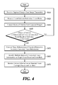
- FIG. 4 is a flowchart of a method performed by an event detecting apparatus for detecting an event, according to at least one embodiment of the present disclosure.
- the event detecting apparatus 150 receives, from the image transmitter 120, images captured from the image capture apparatus 110 (S410).
- the image capture apparatus 110 is implemented as multiple cameras and the event detecting apparatus 150 acquires a plurality of images captured respectively by the multiple cameras.
- the event detecting apparatus 150 receives an event rule and individual event rules from the individual event rule generating apparatus 140 (S420).
- the event rule means an event rule for a main image generated through a predetermined conversion function in the individual event rule generating apparatus 140 and the individual event rules indicate rules corresponding respectively to the multiple cameras, which are converted through predetermined conversion functions corresponding to coordinate systems of the cameras.
- the event detecting apparatus 150 extracts an object-of-interest from the captured images (S430).
- the event detecting apparatus 150 compares pre-stored background images with the captured images and determines a different part therebetween as a moving object-of-interest, thereby extracting trace information of the object-of-interest.
- the trace information is expressed by a coordinate value (e.g. (x, y)) at which the object-of-interest is located, but not restricted thereto.
- the trace information is a distance value from a predetermined reference.
- the pre-stored background images are background images pre-captured by the multiple cameras and represent images indicating a still background for a predetermined time rather than a moving object-of-interest in the captured images.
- the event detecting apparatus 150 determines whether the object-of-interest corresponds to an individual event based on the individual event rules received in Step S420 (S440). The event detecting apparatus 150 determines whether the object-of-interest generates an individual event in which the object-of-interest passes through a region-of-interest by confirming whether a sign value of the trace information of the object-of-interest is changed based on the individual event rules.
- the event detecting apparatus 150 extracts trace information of a moving object-of-interest from the captured images and identify an object-of-interest in which the sign value for the trace information is changed from '+' to '-' as an individual event.
- the event detecting apparatus 150 If the object-of-interest corresponds to the individual event, the event detecting apparatus 150 generates inverse trace information through a predetermined conversion function from the trace information of the object-of-interest (S450).
- the inversely converted trace information is generated by inversely converting the trace information of the object-of-interest corresponding to the individual event through a conversion function such as homography and calibration for correcting a distorted image using a coordinate system of a camera.
- the event detecting apparatus 150 identifies the object-of-interest as a single event (S460). If the inversely converted trace information is included in a region-of-interest based on a preset event rule and if it is determined that a sign value of the inversely converted trace information is changed, the event detecting apparatus 150 identifies the object-of-interest as an event.
- the event detecting apparatus 150 performs monitoring by displaying and alerting output information for the detected event (S470).
- Steps S410 to S470 of FIG. 4 have been described as being sequentially performed, this is only an exemplary description of the technical idea of at least one embodiment of the present disclosure. Those skilled in the art will appreciate that various modifications, additions and substitutions are possible, without departing from the characteristics of at least one embodiment of the present disclosure. For example, the order of steps shown in FIG. 4 are able to be changed, or one or more of Steps S410 to S470 may be performed in parallel. Therefore, the present disclosure is not limited to the time-series order as shown in FIG. 4 .
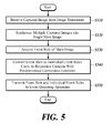
- FIG. 5 is a flowchart of a method performed by an individual event rule generating apparatus for generating an individual event rule according to at least one embodiment of the present disclosure.
- the individual event rule generator 140 receives, from the image transmitter 120, images captured from the image capture apparatus 110 (S510).
- the image capture apparatus 110 includes a plurality of cameras and the individual event rule generator 140 acquires a plurality of captured images captured respectively by the cameras.
- the individual event rule generator 140 synthesizes the captured images into one main image through predetermined conversion functions corresponding to coordinate systems of the cameras (S520).
- the predetermined conversion functions are functions using a homography and calibration scheme for correcting a distorted image using the coordinate system.
- the individual event rule generating apparatus 140 acquires an event rule for the main image (S530).
- the event rule is a rule set through manipulation of a manager for the main image in which the captured images are synthesized and means conditional information for recognizing operation in which an object-of-interest passes through a region-of-interest generated through a setting command of a manager such as interface manipulation or coordinate input as an event.
- the individual event rule generating apparatus 140 converts an event rule for the main image into individual event rules corresponding respectively to the cameras using the predetermined conversion functions corresponding to the coordinate systems of the cameras (S540). For example, if an event rule set as a region-of-interest in the form of a circle in the main image is acquired, the individual event rule generating apparatus 140 converts the left semi-circle of the region-of-interest into a first individual event rule through a conversion function corresponding to the first camera 112 and convert the right semi-circle of the region-of-interest into a second individual event rule through a conversion function corresponding to the second camera 114.
- the individual event rule generating apparatus 140 transmits the event rule for the main image and the individual event rules to the event detecting apparatus 150 in order to detect an object-of-interest corresponding to an event (S550).
- Steps S510 to S550 of FIG. 5 have been described as being sequentially performed, this is only an exemplary description of the technical idea of at least one embodiment of the present disclosure. Those skilled in the art will appreciate that various modifications, additions and substitutions are possible, without departing from the spirit and scope of the claimed invention. For example, the order of steps shown in FIG. 5 is able to be changed, or one or more of Steps S510 to S550 is able to be performed in parallel. Therefore, the present disclosure is not limited to the time-series order as shown in FIG. 5 .
- the present disclosure is highly useful for application to an apparatus and a method for detecting an event from multiple captured images, by converting an event rule for a synthesized image from the multiple captured images through conversion functions corresponding to the coordinate systems of multiple cameras into individual event rules as a basis for determining multiple individual events, and identifying the determined multiple individual events through the predetermined conversion functions as the single event. Therefore, multiple event rules need not be set, repeated events are not detected, and events can be easily stored, identified and managed.
Landscapes
- Engineering & Computer Science (AREA)
- Multimedia (AREA)
- Physics & Mathematics (AREA)
- General Physics & Mathematics (AREA)
- Theoretical Computer Science (AREA)
- Computer Vision & Pattern Recognition (AREA)
- Signal Processing (AREA)
- Closed-Circuit Television Systems (AREA)
- Image Analysis (AREA)
- Studio Devices (AREA)
Applications Claiming Priority (2)
| Application Number | Priority Date | Filing Date | Title |
|---|---|---|---|
| KR1020120106797A KR101937272B1 (ko) | 2012-09-25 | 2012-09-25 | 복수 개의 촬영영상으로부터 이벤트를 검출하는 장치 및 방법 |
| PCT/KR2013/008592 WO2014051337A1 (fr) | 2012-09-25 | 2013-09-25 | Appareil et procédé pour détecter un événement à partir d'une pluralité d'images photographiées |
Publications (3)
| Publication Number | Publication Date |
|---|---|
| EP2903261A1 true EP2903261A1 (fr) | 2015-08-05 |
| EP2903261A4 EP2903261A4 (fr) | 2016-10-26 |
| EP2903261B1 EP2903261B1 (fr) | 2020-11-25 |
Family
ID=50388638
Family Applications (1)
| Application Number | Title | Priority Date | Filing Date |
|---|---|---|---|
| EP13840942.0A Active EP2903261B1 (fr) | 2012-09-25 | 2013-09-25 | Appareil et procédé pour détecter un événement à partir d'une pluralité d'images photographiées |
Country Status (5)
| Country | Link |
|---|---|
| US (1) | US9639937B2 (fr) |
| EP (1) | EP2903261B1 (fr) |
| KR (1) | KR101937272B1 (fr) |
| CN (1) | CN104704816B (fr) |
| WO (1) | WO2014051337A1 (fr) |
Cited By (1)
| Publication number | Priority date | Publication date | Assignee | Title |
|---|---|---|---|---|
| EP3310044A1 (fr) * | 2016-10-14 | 2018-04-18 | Synology Incorporated | Procédé et appareil associé pour réaliser un comptage coopératif avec le aide de plusieurs caméras |
Families Citing this family (14)
| Publication number | Priority date | Publication date | Assignee | Title |
|---|---|---|---|---|
| WO2014051262A1 (fr) * | 2012-09-25 | 2014-04-03 | 에스케이텔레콤 주식회사 | Procédé d'établissement de règles d'événement et appareil de surveillance d'événement l'utilisant |
| KR101632198B1 (ko) * | 2015-02-10 | 2016-07-01 | 주식회사 일리시스 | 객체 이동 시간 기반 관심 영역 이벤트 발생 감지 방법 |
| EP3159853B1 (fr) * | 2015-10-23 | 2019-03-27 | Harman International Industries, Incorporated | Systèmes et procédés d'analyse avancée d'assistance au conducteur |
| US10592749B2 (en) * | 2016-11-14 | 2020-03-17 | General Electric Company | Systems and methods for analyzing turns at an airport |
| KR102634188B1 (ko) | 2016-11-30 | 2024-02-05 | 한화비전 주식회사 | 영상 감시 시스템 |
| JP6844503B2 (ja) * | 2017-11-06 | 2021-03-17 | 京セラドキュメントソリューションズ株式会社 | 監視システム |
| CN109974667B (zh) * | 2017-12-27 | 2021-07-23 | 宁波方太厨具有限公司 | 一种室内人体定位方法 |
| JP6915575B2 (ja) * | 2018-03-29 | 2021-08-04 | 京セラドキュメントソリューションズ株式会社 | 制御装置及び監視システム |
| CN109872483B (zh) * | 2019-02-22 | 2020-09-29 | 华中光电技术研究所(中国船舶重工集团有限公司第七一七研究所) | 一种入侵警戒光电监测系统及方法 |
| KR102247359B1 (ko) * | 2019-07-31 | 2021-05-04 | (주)유디피 | 원격 모니터링을 위한 영상 분석 시스템 및 방법 |
| CN113099173A (zh) * | 2021-03-25 | 2021-07-09 | 湖南桥康智能科技有限公司 | 一种具有物体位移测量计算功能的智能网络摄像机 |
| CN112797900B (zh) * | 2021-04-07 | 2021-07-06 | 中科慧远视觉技术(北京)有限公司 | 多相机板材尺寸测量方法 |
| EP4106328B1 (fr) * | 2021-06-17 | 2025-10-08 | Honeywell International Inc. | Système de vidéosurveillance à intelligence distribuée |
| CN114170752A (zh) * | 2021-12-08 | 2022-03-11 | 潍坊欣龙生物材料有限公司 | 周界安防的监视方法 |
Family Cites Families (20)
| Publication number | Priority date | Publication date | Assignee | Title |
|---|---|---|---|---|
| CA2296439C (fr) | 1997-07-15 | 2009-09-15 | Kia Silverbrook | Appareil photographique a systeme d'impression interne |
| US8564661B2 (en) * | 2000-10-24 | 2013-10-22 | Objectvideo, Inc. | Video analytic rule detection system and method |
| KR100940237B1 (ko) * | 2003-03-06 | 2010-02-04 | 삼성테크윈 주식회사 | 이벤트 발생과 연동하여 모니터링 및 레코딩 제어가가능한 감시시스템 및 그 제어방법 |
| WO2006022630A1 (fr) * | 2004-07-26 | 2006-03-02 | Silicon Optix, Inc. | Systeme est procede de vision panoramique |
| KR100872878B1 (ko) * | 2006-09-29 | 2008-12-10 | (주)로그시스 | 감시 카메라의 이벤트 검출 촬영시스템 |
| KR101187908B1 (ko) * | 2007-09-11 | 2012-10-05 | 삼성테크윈 주식회사 | 복수의 이벤트 영상을 표시하는 통합 감시 시스템 및 이를이용한 복수의 이벤트 영상 표시 방법 |
| CN101119482B (zh) * | 2007-09-28 | 2011-07-20 | 北京智安邦科技有限公司 | 一种全景监控方法及设备 |
| KR20090035379A (ko) * | 2007-10-05 | 2009-04-09 | 주식회사 케이티 | 주차장내 영상감지를 이용한 지능형 보안방범 시스템 및 그제어방법 |
| KR100924580B1 (ko) * | 2007-12-26 | 2009-10-30 | (주)네스테크놀로지 | 영상신호 감시용 신호변환기 통합 영상 감시 시스템 |
| US20090195382A1 (en) * | 2008-01-31 | 2009-08-06 | Sensormatic Electronics Corporation | Video sensor and alarm system and method with object and event classification |
| KR100954375B1 (ko) * | 2008-05-06 | 2010-04-26 | (주) 티앤엑스시스템즈 | 지능형 영상 감시 시스템 |
| US8570376B1 (en) * | 2008-11-19 | 2013-10-29 | Videomining Corporation | Method and system for efficient sampling of videos using spatiotemporal constraints for statistical behavior analysis |
| US8416296B2 (en) * | 2009-04-14 | 2013-04-09 | Behavioral Recognition Systems, Inc. | Mapper component for multiple art networks in a video analysis system |
| US8503539B2 (en) * | 2010-02-26 | 2013-08-06 | Bao Tran | High definition personal computer (PC) cam |
| KR20110136907A (ko) * | 2010-06-16 | 2011-12-22 | 주식회사 영국전자 | 광역 감시 시스템 및 이에 있어서의 감시 데이터 처리 방법 |
| KR101180887B1 (ko) * | 2010-09-08 | 2012-09-07 | 중앙대학교 산학협력단 | 이상행위 검출장치 및 방법 |
| CN102045544A (zh) * | 2010-11-10 | 2011-05-04 | 无锡中星微电子有限公司 | 一种视频监控系统及其视频数据的传输方法 |
| CN102510482A (zh) * | 2011-11-29 | 2012-06-20 | 蔡棽 | 一种提高能见度和可视距离的图像拼接重建及全局监控方法 |
| US9530060B2 (en) * | 2012-01-17 | 2016-12-27 | Avigilon Fortress Corporation | System and method for building automation using video content analysis with depth sensing |
| JP6148480B2 (ja) * | 2012-04-06 | 2017-06-14 | キヤノン株式会社 | 画像処理装置、画像処理方法 |
-
2012
- 2012-09-25 KR KR1020120106797A patent/KR101937272B1/ko active Active
-
2013
- 2013-09-25 WO PCT/KR2013/008592 patent/WO2014051337A1/fr not_active Ceased
- 2013-09-25 CN CN201380049910.2A patent/CN104704816B/zh active Active
- 2013-09-25 EP EP13840942.0A patent/EP2903261B1/fr active Active
-
2015
- 2015-03-24 US US14/667,552 patent/US9639937B2/en active Active
Cited By (2)
| Publication number | Priority date | Publication date | Assignee | Title |
|---|---|---|---|---|
| EP3310044A1 (fr) * | 2016-10-14 | 2018-04-18 | Synology Incorporated | Procédé et appareil associé pour réaliser un comptage coopératif avec le aide de plusieurs caméras |
| US10223592B2 (en) | 2016-10-14 | 2019-03-05 | Synology Incorporated | Method and associated apparatus for performing cooperative counting with aid of multiple cameras |
Also Published As
| Publication number | Publication date |
|---|---|
| EP2903261B1 (fr) | 2020-11-25 |
| US9639937B2 (en) | 2017-05-02 |
| EP2903261A4 (fr) | 2016-10-26 |
| US20150199815A1 (en) | 2015-07-16 |
| WO2014051337A1 (fr) | 2014-04-03 |
| CN104704816B (zh) | 2018-06-01 |
| KR101937272B1 (ko) | 2019-04-09 |
| CN104704816A (zh) | 2015-06-10 |
| KR20140039927A (ko) | 2014-04-02 |
Similar Documents
| Publication | Publication Date | Title |
|---|---|---|
| EP2903261A1 (fr) | Appareil et procédé pour détecter un événement à partir d'une pluralité d'images photographiées | |
| JP6644827B2 (ja) | ビデオ監視システム並びにビデオ監視方法 | |
| KR102045871B1 (ko) | 인공지능 기술에 기반한 화재감지시스템 및 인공지능 기술에 기반한 화재감지방법 | |
| KR101793636B1 (ko) | 통합 지능형 cctv 영상 처리 시스템 | |
| EP2966852B1 (fr) | Procédé, dispositif, et système de vidéo surveillance | |
| KR101570339B1 (ko) | 영상분석 서버를 통한 미래 발생범죄 예측 시스템 | |
| KR101471846B1 (ko) | Fx 감시카메라를 제어하는 콘트롤박스 및 fx 보안 시스템 및 fx 보안시스템 제어방법 | |
| KR101513215B1 (ko) | 객체 행동패턴 cctv 영상 분석서버 | |
| KR101397453B1 (ko) | 영상 감시 시스템 및 그 방법 | |
| KR101084914B1 (ko) | 차량번호 및 사람 이미지의 인덱싱 관리시스템 | |
| KR101352337B1 (ko) | 지능형 다기능 현장 감시 장치 및 그 방법 | |
| JP2007158421A (ja) | 監視カメラシステム及び顔画像追跡記録方法 | |
| KR101921868B1 (ko) | 고해상도 카메라를 이용한 지능형 영상 감시 시스템 및 그 방법 | |
| KR101485512B1 (ko) | 객체 행동패턴의 해마 신경망 학습을 이용한 미래범죄 발생확률 우선순위 이벤트 cctv 영상처리 방법 | |
| KR101298684B1 (ko) | 무 감지센서 기반의 차량 번호 인식 시스템 및 그 동작방법 | |
| KR20160053601A (ko) | 영상 처리 장치 및 방법 | |
| KR101492473B1 (ko) | 사용자 기반 상황 인지형 씨씨티비 통합관제시스템 | |
| KR20110109147A (ko) | 방범 시스템 | |
| KR101621822B1 (ko) | 하이브리드 이미지 전송 기반의 방범겸용 차량번호 인식 장치, 그리고 이를 이용한 차량번호 인식 및 제공 방법 | |
| KR20150112712A (ko) | 객체 행동패턴 cctv 영상 분석서버 | |
| KR102056854B1 (ko) | 아이피(ip) 비디오 월 시스템 및 이의 구동방법 | |
| KR102113527B1 (ko) | 열화상 ip cctv 시스템 및 이를 통한 화재 감지 방법 | |
| KR101436283B1 (ko) | 영상분석 서버를 통한 미래 발생범죄 예측 시스템 | |
| KR20100077662A (ko) | 지능형 영상감시 시스템 및 영상감시 방법 | |
| KR101465314B1 (ko) | 원격지의 모니터링 시스템을 관리하는 온라인 관리 및 보수 시스템 및 그 방법 |
Legal Events
| Date | Code | Title | Description |
|---|---|---|---|
| PUAI | Public reference made under article 153(3) epc to a published international application that has entered the european phase |
Free format text: ORIGINAL CODE: 0009012 |
|
| 17P | Request for examination filed |
Effective date: 20150427 |
|
| AK | Designated contracting states |
Kind code of ref document: A1 Designated state(s): AL AT BE BG CH CY CZ DE DK EE ES FI FR GB GR HR HU IE IS IT LI LT LU LV MC MK MT NL NO PL PT RO RS SE SI SK SM TR |
|
| AX | Request for extension of the european patent |
Extension state: BA ME |
|
| DAX | Request for extension of the european patent (deleted) | ||
| RA4 | Supplementary search report drawn up and despatched (corrected) |
Effective date: 20160927 |
|
| RIC1 | Information provided on ipc code assigned before grant |
Ipc: H04N 7/18 20060101AFI20160920BHEP Ipc: G06T 7/20 20060101ALI20160920BHEP Ipc: G06K 9/00 20060101ALI20160920BHEP |
|
| STAA | Information on the status of an ep patent application or granted ep patent |
Free format text: STATUS: EXAMINATION IS IN PROGRESS |
|
| 17Q | First examination report despatched |
Effective date: 20180723 |
|
| GRAP | Despatch of communication of intention to grant a patent |
Free format text: ORIGINAL CODE: EPIDOSNIGR1 |
|
| STAA | Information on the status of an ep patent application or granted ep patent |
Free format text: STATUS: GRANT OF PATENT IS INTENDED |
|
| INTG | Intention to grant announced |
Effective date: 20200619 |
|
| GRAS | Grant fee paid |
Free format text: ORIGINAL CODE: EPIDOSNIGR3 |
|
| GRAA | (expected) grant |
Free format text: ORIGINAL CODE: 0009210 |
|
| STAA | Information on the status of an ep patent application or granted ep patent |
Free format text: STATUS: THE PATENT HAS BEEN GRANTED |
|
| AK | Designated contracting states |
Kind code of ref document: B1 Designated state(s): AL AT BE BG CH CY CZ DE DK EE ES FI FR GB GR HR HU IE IS IT LI LT LU LV MC MK MT NL NO PL PT RO RS SE SI SK SM TR |
|
| REG | Reference to a national code |
Ref country code: GB Ref legal event code: FG4D |
|
| REG | Reference to a national code |
Ref country code: CH Ref legal event code: EP |
|
| REG | Reference to a national code |
Ref country code: AT Ref legal event code: REF Ref document number: 1339640 Country of ref document: AT Kind code of ref document: T Effective date: 20201215 |
|
| REG | Reference to a national code |
Ref country code: DE Ref legal event code: R096 Ref document number: 602013074357 Country of ref document: DE |
|
| REG | Reference to a national code |
Ref country code: IE Ref legal event code: FG4D |
|
| REG | Reference to a national code |
Ref country code: AT Ref legal event code: MK05 Ref document number: 1339640 Country of ref document: AT Kind code of ref document: T Effective date: 20201125 |
|
| REG | Reference to a national code |
Ref country code: NL Ref legal event code: MP Effective date: 20201125 |
|
| PG25 | Lapsed in a contracting state [announced via postgrant information from national office to epo] |
Ref country code: GR Free format text: LAPSE BECAUSE OF FAILURE TO SUBMIT A TRANSLATION OF THE DESCRIPTION OR TO PAY THE FEE WITHIN THE PRESCRIBED TIME-LIMIT Effective date: 20210226 Ref country code: FI Free format text: LAPSE BECAUSE OF FAILURE TO SUBMIT A TRANSLATION OF THE DESCRIPTION OR TO PAY THE FEE WITHIN THE PRESCRIBED TIME-LIMIT Effective date: 20201125 Ref country code: RS Free format text: LAPSE BECAUSE OF FAILURE TO SUBMIT A TRANSLATION OF THE DESCRIPTION OR TO PAY THE FEE WITHIN THE PRESCRIBED TIME-LIMIT Effective date: 20201125 Ref country code: NO Free format text: LAPSE BECAUSE OF FAILURE TO SUBMIT A TRANSLATION OF THE DESCRIPTION OR TO PAY THE FEE WITHIN THE PRESCRIBED TIME-LIMIT Effective date: 20210225 Ref country code: PT Free format text: LAPSE BECAUSE OF FAILURE TO SUBMIT A TRANSLATION OF THE DESCRIPTION OR TO PAY THE FEE WITHIN THE PRESCRIBED TIME-LIMIT Effective date: 20210325 |
|
| PG25 | Lapsed in a contracting state [announced via postgrant information from national office to epo] |
Ref country code: LV Free format text: LAPSE BECAUSE OF FAILURE TO SUBMIT A TRANSLATION OF THE DESCRIPTION OR TO PAY THE FEE WITHIN THE PRESCRIBED TIME-LIMIT Effective date: 20201125 Ref country code: IS Free format text: LAPSE BECAUSE OF FAILURE TO SUBMIT A TRANSLATION OF THE DESCRIPTION OR TO PAY THE FEE WITHIN THE PRESCRIBED TIME-LIMIT Effective date: 20210325 Ref country code: PL Free format text: LAPSE BECAUSE OF FAILURE TO SUBMIT A TRANSLATION OF THE DESCRIPTION OR TO PAY THE FEE WITHIN THE PRESCRIBED TIME-LIMIT Effective date: 20201125 Ref country code: SE Free format text: LAPSE BECAUSE OF FAILURE TO SUBMIT A TRANSLATION OF THE DESCRIPTION OR TO PAY THE FEE WITHIN THE PRESCRIBED TIME-LIMIT Effective date: 20201125 Ref country code: BG Free format text: LAPSE BECAUSE OF FAILURE TO SUBMIT A TRANSLATION OF THE DESCRIPTION OR TO PAY THE FEE WITHIN THE PRESCRIBED TIME-LIMIT Effective date: 20210225 Ref country code: AT Free format text: LAPSE BECAUSE OF FAILURE TO SUBMIT A TRANSLATION OF THE DESCRIPTION OR TO PAY THE FEE WITHIN THE PRESCRIBED TIME-LIMIT Effective date: 20201125 |
|
| REG | Reference to a national code |
Ref country code: LT Ref legal event code: MG9D |
|
| PG25 | Lapsed in a contracting state [announced via postgrant information from national office to epo] |
Ref country code: HR Free format text: LAPSE BECAUSE OF FAILURE TO SUBMIT A TRANSLATION OF THE DESCRIPTION OR TO PAY THE FEE WITHIN THE PRESCRIBED TIME-LIMIT Effective date: 20201125 |
|
| PG25 | Lapsed in a contracting state [announced via postgrant information from national office to epo] |
Ref country code: LT Free format text: LAPSE BECAUSE OF FAILURE TO SUBMIT A TRANSLATION OF THE DESCRIPTION OR TO PAY THE FEE WITHIN THE PRESCRIBED TIME-LIMIT Effective date: 20201125 Ref country code: RO Free format text: LAPSE BECAUSE OF FAILURE TO SUBMIT A TRANSLATION OF THE DESCRIPTION OR TO PAY THE FEE WITHIN THE PRESCRIBED TIME-LIMIT Effective date: 20201125 Ref country code: SK Free format text: LAPSE BECAUSE OF FAILURE TO SUBMIT A TRANSLATION OF THE DESCRIPTION OR TO PAY THE FEE WITHIN THE PRESCRIBED TIME-LIMIT Effective date: 20201125 Ref country code: SM Free format text: LAPSE BECAUSE OF FAILURE TO SUBMIT A TRANSLATION OF THE DESCRIPTION OR TO PAY THE FEE WITHIN THE PRESCRIBED TIME-LIMIT Effective date: 20201125 Ref country code: EE Free format text: LAPSE BECAUSE OF FAILURE TO SUBMIT A TRANSLATION OF THE DESCRIPTION OR TO PAY THE FEE WITHIN THE PRESCRIBED TIME-LIMIT Effective date: 20201125 Ref country code: CZ Free format text: LAPSE BECAUSE OF FAILURE TO SUBMIT A TRANSLATION OF THE DESCRIPTION OR TO PAY THE FEE WITHIN THE PRESCRIBED TIME-LIMIT Effective date: 20201125 |
|
| REG | Reference to a national code |
Ref country code: DE Ref legal event code: R097 Ref document number: 602013074357 Country of ref document: DE |
|
| PG25 | Lapsed in a contracting state [announced via postgrant information from national office to epo] |
Ref country code: DK Free format text: LAPSE BECAUSE OF FAILURE TO SUBMIT A TRANSLATION OF THE DESCRIPTION OR TO PAY THE FEE WITHIN THE PRESCRIBED TIME-LIMIT Effective date: 20201125 |
|
| PLBE | No opposition filed within time limit |
Free format text: ORIGINAL CODE: 0009261 |
|
| STAA | Information on the status of an ep patent application or granted ep patent |
Free format text: STATUS: NO OPPOSITION FILED WITHIN TIME LIMIT |
|
| PG25 | Lapsed in a contracting state [announced via postgrant information from national office to epo] |
Ref country code: NL Free format text: LAPSE BECAUSE OF FAILURE TO SUBMIT A TRANSLATION OF THE DESCRIPTION OR TO PAY THE FEE WITHIN THE PRESCRIBED TIME-LIMIT Effective date: 20201125 Ref country code: AL Free format text: LAPSE BECAUSE OF FAILURE TO SUBMIT A TRANSLATION OF THE DESCRIPTION OR TO PAY THE FEE WITHIN THE PRESCRIBED TIME-LIMIT Effective date: 20201125 Ref country code: IT Free format text: LAPSE BECAUSE OF FAILURE TO SUBMIT A TRANSLATION OF THE DESCRIPTION OR TO PAY THE FEE WITHIN THE PRESCRIBED TIME-LIMIT Effective date: 20201125 |
|
| 26N | No opposition filed |
Effective date: 20210826 |
|
| PG25 | Lapsed in a contracting state [announced via postgrant information from national office to epo] |
Ref country code: SI Free format text: LAPSE BECAUSE OF FAILURE TO SUBMIT A TRANSLATION OF THE DESCRIPTION OR TO PAY THE FEE WITHIN THE PRESCRIBED TIME-LIMIT Effective date: 20201125 Ref country code: ES Free format text: LAPSE BECAUSE OF FAILURE TO SUBMIT A TRANSLATION OF THE DESCRIPTION OR TO PAY THE FEE WITHIN THE PRESCRIBED TIME-LIMIT Effective date: 20201125 |
|
| REG | Reference to a national code |
Ref country code: CH Ref legal event code: PL |
|
| REG | Reference to a national code |
Ref country code: BE Ref legal event code: MM Effective date: 20210930 |
|
| PG25 | Lapsed in a contracting state [announced via postgrant information from national office to epo] |
Ref country code: IS Free format text: LAPSE BECAUSE OF FAILURE TO SUBMIT A TRANSLATION OF THE DESCRIPTION OR TO PAY THE FEE WITHIN THE PRESCRIBED TIME-LIMIT Effective date: 20210325 Ref country code: MC Free format text: LAPSE BECAUSE OF FAILURE TO SUBMIT A TRANSLATION OF THE DESCRIPTION OR TO PAY THE FEE WITHIN THE PRESCRIBED TIME-LIMIT Effective date: 20201125 |
|
| PG25 | Lapsed in a contracting state [announced via postgrant information from national office to epo] |
Ref country code: LU Free format text: LAPSE BECAUSE OF NON-PAYMENT OF DUE FEES Effective date: 20210925 Ref country code: IE Free format text: LAPSE BECAUSE OF NON-PAYMENT OF DUE FEES Effective date: 20210925 Ref country code: FR Free format text: LAPSE BECAUSE OF NON-PAYMENT OF DUE FEES Effective date: 20210930 Ref country code: BE Free format text: LAPSE BECAUSE OF NON-PAYMENT OF DUE FEES Effective date: 20210930 |
|
| PG25 | Lapsed in a contracting state [announced via postgrant information from national office to epo] |
Ref country code: LI Free format text: LAPSE BECAUSE OF NON-PAYMENT OF DUE FEES Effective date: 20210930 Ref country code: CH Free format text: LAPSE BECAUSE OF NON-PAYMENT OF DUE FEES Effective date: 20210930 |
|
| PG25 | Lapsed in a contracting state [announced via postgrant information from national office to epo] |
Ref country code: HU Free format text: LAPSE BECAUSE OF FAILURE TO SUBMIT A TRANSLATION OF THE DESCRIPTION OR TO PAY THE FEE WITHIN THE PRESCRIBED TIME-LIMIT; INVALID AB INITIO Effective date: 20130925 |
|
| PG25 | Lapsed in a contracting state [announced via postgrant information from national office to epo] |
Ref country code: CY Free format text: LAPSE BECAUSE OF FAILURE TO SUBMIT A TRANSLATION OF THE DESCRIPTION OR TO PAY THE FEE WITHIN THE PRESCRIBED TIME-LIMIT Effective date: 20201125 |
|
| P01 | Opt-out of the competence of the unified patent court (upc) registered |
Effective date: 20230602 |
|
| PG25 | Lapsed in a contracting state [announced via postgrant information from national office to epo] |
Ref country code: MK Free format text: LAPSE BECAUSE OF FAILURE TO SUBMIT A TRANSLATION OF THE DESCRIPTION OR TO PAY THE FEE WITHIN THE PRESCRIBED TIME-LIMIT Effective date: 20201125 |
|
| PG25 | Lapsed in a contracting state [announced via postgrant information from national office to epo] |
Ref country code: MT Free format text: LAPSE BECAUSE OF FAILURE TO SUBMIT A TRANSLATION OF THE DESCRIPTION OR TO PAY THE FEE WITHIN THE PRESCRIBED TIME-LIMIT Effective date: 20201125 |
|
| PGFP | Annual fee paid to national office [announced via postgrant information from national office to epo] |
Ref country code: DE Payment date: 20250702 Year of fee payment: 13 |
|
| PGFP | Annual fee paid to national office [announced via postgrant information from national office to epo] |
Ref country code: GB Payment date: 20250703 Year of fee payment: 13 |
|
| PG25 | Lapsed in a contracting state [announced via postgrant information from national office to epo] |
Ref country code: TR Free format text: LAPSE BECAUSE OF FAILURE TO SUBMIT A TRANSLATION OF THE DESCRIPTION OR TO PAY THE FEE WITHIN THE PRESCRIBED TIME-LIMIT Effective date: 20201125 |