EP2903400A2 - Dispositif électronique - Google Patents
Dispositif électronique Download PDFInfo
- Publication number
- EP2903400A2 EP2903400A2 EP15150860.3A EP15150860A EP2903400A2 EP 2903400 A2 EP2903400 A2 EP 2903400A2 EP 15150860 A EP15150860 A EP 15150860A EP 2903400 A2 EP2903400 A2 EP 2903400A2
- Authority
- EP
- European Patent Office
- Prior art keywords
- plug
- module
- electronic device
- baseplate
- function
- Prior art date
- Legal status (The legal status is an assumption and is not a legal conclusion. Google has not performed a legal analysis and makes no representation as to the accuracy of the status listed.)
- Granted
Links
Images


Classifications
-
- H—ELECTRICITY
- H01—ELECTRIC ELEMENTS
- H01R—ELECTRICALLY-CONDUCTIVE CONNECTIONS; STRUCTURAL ASSOCIATIONS OF A PLURALITY OF MUTUALLY-INSULATED ELECTRICAL CONNECTING ELEMENTS; COUPLING DEVICES; CURRENT COLLECTORS
- H01R13/00—Details of coupling devices of the kinds covered by groups H01R12/70 or H01R24/00 - H01R33/00
- H01R13/62—Means for facilitating engagement or disengagement of coupling parts or for holding them in engagement
- H01R13/629—Additional means for facilitating engagement or disengagement of coupling parts, e.g. aligning or guiding means, levers, gas pressure electrical locking indicators, manufacturing tolerances
-
- H—ELECTRICITY
- H01—ELECTRIC ELEMENTS
- H01R—ELECTRICALLY-CONDUCTIVE CONNECTIONS; STRUCTURAL ASSOCIATIONS OF A PLURALITY OF MUTUALLY-INSULATED ELECTRICAL CONNECTING ELEMENTS; COUPLING DEVICES; CURRENT COLLECTORS
- H01R13/00—Details of coupling devices of the kinds covered by groups H01R12/70 or H01R24/00 - H01R33/00
- H01R13/66—Structural association with built-in electrical component
- H01R13/68—Structural association with built-in electrical component with built-in fuse
-
- H—ELECTRICITY
- H01—ELECTRIC ELEMENTS
- H01R—ELECTRICALLY-CONDUCTIVE CONNECTIONS; STRUCTURAL ASSOCIATIONS OF A PLURALITY OF MUTUALLY-INSULATED ELECTRICAL CONNECTING ELEMENTS; COUPLING DEVICES; CURRENT COLLECTORS
- H01R13/00—Details of coupling devices of the kinds covered by groups H01R12/70 or H01R24/00 - H01R33/00
- H01R13/66—Structural association with built-in electrical component
- H01R13/717—Structural association with built-in electrical component with built-in light source
- H01R13/7175—Light emitting diodes (LEDs)
-
- H—ELECTRICITY
- H01—ELECTRIC ELEMENTS
- H01R—ELECTRICALLY-CONDUCTIVE CONNECTIONS; STRUCTURAL ASSOCIATIONS OF A PLURALITY OF MUTUALLY-INSULATED ELECTRICAL CONNECTING ELEMENTS; COUPLING DEVICES; CURRENT COLLECTORS
- H01R24/00—Two-part coupling devices, or either of their cooperating parts, characterised by their overall structure
- H01R24/66—Two-part coupling devices, or either of their cooperating parts, characterised by their overall structure with pins, blades or analogous contacts and secured to apparatus or structure, e.g. to a wall
-
- H—ELECTRICITY
- H05—ELECTRIC TECHNIQUES NOT OTHERWISE PROVIDED FOR
- H05K—PRINTED CIRCUITS; CASINGS OR CONSTRUCTIONAL DETAILS OF ELECTRIC APPARATUS; MANUFACTURE OF ASSEMBLAGES OF ELECTRICAL COMPONENTS
- H05K7/00—Constructional details common to different types of electric apparatus
- H05K7/14—Mounting supporting structure in casing or on frame or rack
- H05K7/1462—Mounting supporting structure in casing or on frame or rack for programmable logic controllers [PLC] for automation or industrial process control
- H05K7/1465—Modular PLC assemblies with separable functional units
Definitions
- the disclosure relates to an electronic device. More specifically, the disclosure relates to an electronic device in which a plug-in module, which includes a printed substrate on which an electronic circuit is mounted, is detachably connected to a terminal board disposed on a baseplate.
- a device in which a plurality of plug-in modules, which include a printed substrate on which an electronic circuit is mounted, is detachably connected to a terminal board disposed on a baseplate.
- FIG. 11 is a drawing illustrating an example of a control system including the electronic device.
- a field control station 10 communicates with various types of computers such as a remote operation monitoring server, a human interface station, an SMTP server, an engineering station, a safety control station, an advanced process control station, an integration gateway station, and a general-purpose subsystem gateway.
- the field control station 10 is detachably connected to a first terminal board in which input-output modules 11 and various types of function modules 12 are disposed on a baseplate (not shown).
- the function modules 12 are such as a control module which controls transmitting/receiving various types of signals to/from a host system and an electrical power supply module.
- the field control station 10 is connected to a second terminal board 30 with a cable 20.
- a connector 31 to which the cable 20 of a system side is detachably connected, a terminal block 32 to which a cable of a field side is connected, and a disconnecting member 33 are disposed on the second terminal board 30.
- the terminal block 32 is connected to a field device (for example, a sensing device, a motor, and a valve) with the cable of the field side.
- the disconnecting member 33 mechanically disconnects, if needed, a signal connection between the connector 31 and the terminal block 32.
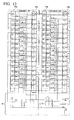
- FIG. 12 is a drawing illustrating the second terminal board 30.
- FIG. 13 is a circuit block diagram of the second terminal board 30.
- a wiring member which is capable of being inserted and ejected with a connector is used as the disconnecting member 33.
- the disconnecting member 33 checks a state of the signal connections of the system side and a state of the signal connections of the field side individually.
- the signal input-output connection between the system side and the field side is disconnected mechanically by ejecting the disconnecting member 33 from the second terminal board 30.
- the fuse 34 fuses to protect the signal connection when a large current which is more than a predetermined current flows.
- the fuse 34 is series-connected to the disconnecting member 33.
- auxiliary components such as a relay and an LED (Light Emitting Diode) are mounted on the second terminal board 30.
- the circuit of the second terminal board 30 is divided into a left block and a right block. Channels 1 through 16 are disposed in the left block. Channels 17 through 32 are disposed in the right block. A series circuit which is equipped with the disconnecting member 33 and the fuse 34 is disposed in each of the channels. The disconnecting members 33a and the fuses 34a are disposed in the channel 1 through 16. The disconnecting members 33b and the fuses 34b are disposed in the channel 17 through 32.
- a duplexed electrical power supply block 35 for driving the left block and the right block is disposed under the left block and the right block.
- FIG. 14A through FIG. 14E there are electronic devices which are terminal blocks separated from the second terminal board 30.
- An electronic device 141 shown in FIG. 14A , an electronic device 142 shown in FIG. 14B , and an electronic device 143 shown in FIG. 14C are disconnecting terminal blocks mounted on a DIN (Deutsche Industrie Normen) rail.
- An electronic device 144 shown in FIG. 14D and an electronic device 145 shown in FIG. 14E are relay terminal blocks mounted on a terminal board.
- a terminal board which can be fixed on a DIN rail in a small space without sliding laterally, is described.
- a substrate of the terminal board can be stored in a metallic case.
- the field control station 10 which is equipped with the input-output modules 11 and the function modules 12, and the second terminal board 30, which is equipped with the disconnecting member 33 and the fuse 34, are separated.
- a measurement check should be performed by selecting the signal connections of the channels of the field control station 10 and the second terminal board 30 and checking the selected signal connections. Therefore, there is a problem that the work is complicated. Especially, in a case of a large-scale system having many channels, man-hour of the work is to be much more.
- An electronic device may include a plug-in module including a printed substrate on which an electronic circuit is mounted, and a baseplate to which the plug-in module is detachably connected, wherein a system side and a field side are connected with each other, and a predetermined option function is included in the plug-in module.
- Object of some embodiments of the present invention is to provide a comparatively inexpensive electronic device which can reduce mounting space and perform a system establishment and a maintenance check efficiently.
- Another object of some embodiments of the present invention is to provide an electronic device in which a plurality of plug-in modules, which include a printed substrate on which an electronic circuit is mounted, is detachably connected to a terminal board disposed on a baseplate, and the electronic device can stop temporarily and surely before and after connecting to a connector in a case where the plug-in modules are inserted or ejected.
- FIG. 1A is a drawing illustrating a top view of the electronic device.
- FIG. 1B is a drawing illustrating a front view of the electronic device.
- FIG. 1C is a drawing illustrating a right side view of the electronic device.
- FIG. 1D is a drawing illustrating a perspective view of the electronic device.
- two input-output modules 50 which have same functions, a plurality of plug-in modules 60 each of which has a predetermined optional function, and a plurality of terminal blocks 70 are detachably connected to a baseplate 40 with connectors (not shown) respectively.
- the depth of the two input-output modules 50 is longer than the depth of the plug-in modules 60, and the depth of the plug-in modules 60 is longer than the depth of the terminal blocks 70.
- the two input-output modules 50 communicate with a host device.
- the terminal blocks 70 are equipped with terminals and a supporter which supports the terminals.
- the terminal blocks 70 are connected to field devices (for example, a sensing device, a motor, and a valve) with the cable.
- the two input-output modules 50a and 50b are operated in two modes (ACT / STAND BY).
- one input-output module (for example, 50a) which operates as a master is broken
- another input-output module (for example, 50b) which operates as a slave is to operate as a master alternatively.
- the two duplexed input-output modules 50a and 50b are driven. Therefore, an operation stop caused by the broken input-output modules 50 can be suppressed to a minimum.
- the plug-in modules 60 assign the optional functions such as a signal conversion function, an insulation function, a disconnect function, and a fuse function to each of the signal connections individually.
- a front of the plug-in modules 60 one end of a front lever 61 is mounted rotatably with respect to an axis.
- the front lever 61 is mounted with covering the front of the plug-in modules 60. Specific examples of the plug-in modules 60 will be described later.
- the disconnecting member 33 disposed in the second terminal board 30 can be omitted.
- the optional function such as the fuse function can be assigned to the plug-in module 60.
- the fuse function which is assigned to the plug-in modules 60 as the optional function, may be a simple fuse or a fuse having the disconnect function.
- FIG. 2A is a drawing illustrating the electronic device in which all of the sixteen plug-in modules 60 are connected to the baseplate 40.
- the front levers 61 of the plug-in modules 60 cover the front of the plug-in modules 60 respectively.
- FIG. 2B is a drawing illustrating the electronic device in which the front lever 61 of the fifth top plug-in module 60, of the sixteen plug-in module 60 mounted on the baseplate 40, is rotated counterclockwise, and the plug-in module 60 is pulled out to the front direction.
- the front lever 61 By pulling out the front lever 61 to the front direction, the connection between the connector disposed on the baseplate 40 and the plug-in module 60 is released, and the signal connection between the system side and the field side of the fifth top plug-in module 60 is blocked.
- FIG. 2C is a drawing illustrating the electronic device in which the front lever is released and the front lever covers the front of the fifth top plug-in module 60 again.
- the signal connection between the system side and the field side of the fifth top plug-in module 60 is kept to be blocked until the fifth top plug-in module 60 is connected to the connector disposed on the baseplate 40 again.
- FIG. 2D is a drawing illustrating the electronic device in which the fifth top plug-in module 60 is ejected to the front direction. After the fifth top plug-in module 60 is ejected, if needed, the worker inserts a substitute plug-in module 60, which has the same function as the fifth top plug-in module 60, instead of the fifth top plug-in module 60.
- the worker inserts the substitute plug-in module 60 until the substitute plug-in module 60 is connected to the connector disposed on the baseplate 40.
- the electronic device becomes to the state shown in FIG. 2A again.
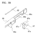
- FIG. 3A is a drawing illustrating an exploded perspective view of the plug-in module 60.
- FIG. 3B is a drawing illustrating a magnified view of a part of FIG. 2A .
- the plug-in module 60 is illustrated upside down.
- the connector connected to the baseplate 40 and parts of the electrical circuit are mounted on a printed substrate 62.
- the printed substrate 62 is stored in a case which is formed to be box-shaped with an upper cover 63 and a lower cover 64 and fixed with a screw 65.
- the front lever 61 which covers the front of the plug-in module 60 is rotatably mounted on the front of the box-shaped case.
- the front lever 61 is mounted on a left side of the front of the plug-in module 60 with an axis so as to rotate clockwise and open in a state that the plug-in module 60 is mounted on the baseplate 40.
- the front lever 61 opens by rotating clockwise in FIG. 3A
- the front lever 61 opens by rotating counterclockwise in a real disposition state ( FIG. 1A through 1D , FIG. 4A through 4E , and FIG. 5A through 5E ).
- the front lever 61 opens by rotating from a side of the terminal block 70 to a side of the input-output module 50b.
- a slit-shaped window 61 a is disposed in the front lever 61 for observing inside of the plug-in module 60. If needed, the window 61a may be equipped with a magnifying lens so as to improve visibility.
- the front lever 61 is formed to be a predetermined shape with elastic synthetic resin. In a case where the front lever 61 is forced to open heavily, the front lever 61 comes free from the axis of the case. For the reason, the breakdown of the plug-in module 60 can be prevented.
- a guide trough 63a is formed on an internal side wall of the upper cover 63 along a longitudinal direction from a front side to a back side of the upper cover 63.
- the guide trough 63a is formed so that a latch drive mechanism can be mounted to be movable in conjunction with the rotation of the front lever 61.
- the latch drive mechanism which is mounted on the guide trough 63a, includes a link bar 66, a latch 67, and a spring 68.
- a projection 66a is formed on the link bar 66.
- the projection 66a acts as a fulcrum point with respect to the guide trough 63a.
- a cut trough 66b is formed in the link bar 66 along a depth direction. The cut trough 66b latches one end of the latch 67.
- a notch 66c is formed at the end of the cut trough 66b in the depth direction.
- An end plane 67a of the latch 67 is a vertical plane perpendicular to the longitudinal direction.
- An upper side 67b of the end plane 67a is formed to be arc-shaped.
- a column-shaped projection 67c for latching the cut trough 66b is disposed on a facing plane of the upper side 67b facing to the link bar 66. The column-shaped projection 67c is latched to the cut trough 66b of the link bar 66, and the latch 67 is slidably connected to the link bar 66.
- FIG. 4A through FIG. 4E are drawings illustrating the plug-in module 60 connected to the baseplate 40.
- FIG. 4A is a drawing illustrating a sectional view on the line A-A illustrated in FIG. 4C .
- FIG. 4B is a drawing illustrating a sectional view on the line B-B illustrated in FIG. 4D.
- FIG. 4C is a drawing illustrating a top view of the plug-in module 60.
- FIG. 4D is a drawing illustrating a front view of the plug-in module 60.
- FIG. 4E is a drawing illustrating a side view of the plug-in module 60.
- a stepped section 41 is disposed near an aperture on the baseplate 40 so as to prevent the plug-in module 60 from pulling out.
- a connector disposed on the printed substrate 62 of the plug-in module 60 is connected to a connector disposed on the baseplate 40.
- the latch 67 is slid along the baseplate 40 with latching the column-shaped projection 67c to the cut trough 66b of the link bar 66.
- the latch 67 engages with the notch 66c formed at the end of the cut trough 66b in the depth direction.
- the front lever 61 is pressed by the spring 68 via the link bar 66 so as to cover the front of the case.
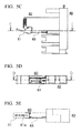
- FIG. 5A through FIG. 5E are drawings illustrating the plug-in module 60 in a case where the connection between the plug-in module 60 and the baseplate 40 is released.
- FIG. 5A is a drawing illustrating a sectional view on the line A-A illustrated in FIG. 5C .
- FIG. 5B is a drawing illustrating a sectional view on the line B-B illustrated in FIG. 5D.
- FIG. 5C is a drawing illustrating a top view of the plug-in module 60.
- FIG. 5D is a drawing illustrating a front view of the plug-in module 60.
- FIG. 5E is a drawing illustrating a side view of the plug-in module 60.
- the end plane 67a of the latch 67 which is latched to the notch 66c formed at the end of the cut trough 66b, rotates and moves along the cut trough 66b with the link bar 66 sliding to the depth direction.
- the end plane 67a of the latch 67 moves along an upper plane of the stepped section 41, and the end plane 67a of the latch 67 slides to the front direction.
- the connection between the connector disposed on the printed substrate 62 of the plug-in module 60 and the connector disposed on the baseplate 40 is released.
- the plug-in module 60 is positioned on a guide member (not shown) which is disposed in the baseplate 40, the plug-in module 60 is held without being pulled out from the baseplate 40.
- the front lever 61 is returned to the position covering the front of the case by a reaction force of the spring 68 at the time when the front lever 61 is rotated counterclockwise against the elastic force of the spring 68.
- Such constitution makes it possible to provide easily, for example, a fuse having the disconnect function, an LED having the disconnect function, and a relay having the disconnect function by adding a function such as a fuse, an LED, and a relay to the plug-in module 60.
- the field control station 10 and the second terminal board 30 are integrated with each other as an electronic device. For the reason, in a case of the operation check when establishing the system or in a case of the maintenance check after establishing the system, the worker can perform the measurement check by selecting only the signal connections of the channels as a measurement target and checking the selected signal connections instead of selecting the signal connections of the channels of the field control station 10 and the second terminal board 30 as measurement target and checking the selected signal connections. Therefore, man-hour of the work can be reduced, and the system establishment and the maintenance check are performed efficiently.
- the mounting space can be reduced.
- FIG. 6 is a drawing illustrating an exploded perspective view of the plug-in module 60 in a second embodiment.
- parts that correspond to those in FIG. 3 are assigned the same reference numerals, and the descriptions thereof will be omitted. Differences between FIG. 6 and FIG. 3 are specific constitutions of the link bar 66 and the latch 67.
- the link bar 66, the latch 67, and the baseplate 40 are changed.
- the plug-in module 60 can stop temporarily and surely before the plug-in module 60 is connected to the connector of the baseplate 40 and after the plug-in module 60 is disconnected from the connector of the baseplate 40.
- An end 67d of the latch 67 is slidably latched to the cut trough 66b.
- the link bar 66 and the latch 67 is stored in the guide trough 63a of the upper cover 63 with the link bar 66 being pressed to the front direction by the spring 68.
- Another end 67e is rotatably mounted on a mounting notch 63b formed near the end of the guide trough 63a in the depth direction.
- a notch 67f is formed in a facing plane of the latch 67 facing to the guide trough 63a.
- the notch 67f engages with a projection 42 before the plug-in module 60 is connected to the connector of the baseplate 40 and after the plug-in module 60 is disconnected from the connector of the baseplate 40.
- the notch 67f performs as an intermediate stopper which temporarily stops the movement of the plug-in module 60.
- FIG. 7 through FIG. 10 are drawings illustrating operations of inserting and ejecting the plug-in module 60.
- FIG. 7A is a drawing illustrating a top view of the plug-in module 60.
- FIG. 7B is a drawing illustrating a sectional view on the line A-A illustrated in FIG. 7A .
- FIG. 8A is a drawing illustrating a top view of the plug-in module 60.
- FIG. 8B is a drawing illustrating a sectional view on the line A-A illustrated in FIG. 8A .
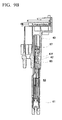
- FIG. 9A is a drawing illustrating a top view of the plug-in module 60.
- FIG. 9B is a drawing illustrating a sectional view on the line A-A illustrated in FIG. 9A .
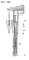
- FIG. 10A is a drawing illustrating a top view of the plug-in module 60.
- FIG. 10B is a drawing illustrating a sectional view on the line A-A illustrated in FIG. 10A .
- FIG. 7A trough FIG. 10B are different from FIG. 6 in the intermediate stopper which is formed on the latch 67 of which a movable end is driven in a vertical direction by the connection member 69.
- FIG. 7A trough FIG. 10B are same as FIG. 6 in that the movable end of the latch 67 is driven in the vertical direction in conjunction with the rotation of the front lever 61.
- the projection 42 is formed on a facing plane of the baseplate 40 facing to the connection member 69. When the projection 42 engages with the notch 67f, the movement of the latch 67 is stopped.
- FIG. 7A and FIG. 7B represent a stably-engaged connection state in which the plug-in module 60 is inserted to the baseplate 40 and the connectors are engaged with each other stably.
- FIG. 8A and FIG. 8B represent an ejection starting state in which the front lever 61 is rotated to an opening direction and the plug-in module 60 is tried to be pulled out from the baseplate 40.
- FIG. 9A and FIG. 9B represent a state in which the plug-in module 60 is pulled out more than FIG. 8A and FIG. 8B .
- FIG. 10A and FIG. 10B represent a state in which the plug-in module 60 is pulled out more than FIG. 9A and FIG. 9B and the intermediate stopper stops the movement of the plug-in module 60 temporarily.
- the front lever 61 is closed, and the front lever covers the front of the plug-in module 60.
- the latch 67 is pressed counterclockwise via the connection member 69.
- the end plane of the movable end of the latch 67 comes into contact with the side plane of the projection 42 formed on the baseplate 40. Therefore, the plug-in module 60 is fixed to the baseplate 40 stably, and the plug-in module 60 and the baseplate 40 are connected with each other by the connectors (not shown).
- the front lever 61 is slightly opened counterclockwise from the front of the plug-in module 60.
- the movable end of the latch 67 is pressed to the downward direction by the connection member 69, and the end plane of the movable end of the latch 67 is not in contact with the side plane of the projection 42 formed on the baseplate 40.
- the plug-in module 60 becomes a state in which the plug-in module 60 can be pulled out from the baseplate 40.
- the plug-in module 60 and the baseplate 40 are kept to be connected with each other by the connectors (not shown).
- the front lever 61 is widely opened counterclockwise from the front of the plug-in module 60.
- the connection between the plug-in module 60 and the baseplate 40 with the connectors (not shown) is released.
- the plug-in module 60 is pulled out to a predetermined intermediate stopping position.
- the notch 67f formed in the latch 67 engages with the projection 42 formed on the baseplate 40.
- the plug-in module 60 becomes a state in which the plug-in module 60 can be pulled out from the baseplate 40. By pulling out the plug-in module 60 strongly, the connection between the plug-in module 60 and the baseplate 40 with the connectors (not shown) is released, and the plug-in module 60 can be pulled out from the baseplate 40.
- FIG. 10A and FIG. 10B represent a state in which the front lever 61 is closed from a state of FIG. 9A and FIG. 9B .
- the projection 42 engages with the notch 67f formed in the latch 67.
- the plug-in module 60 is held at a predetermined intermediate stopping position in a state that the plug-in module 60 is pulled out.
- the plug-in module 60 In a case where pulling out the plug-in module 60 from the baseplate 40, because the plug-in module 60 is temporarily held at the predetermined intermediate stopping position in the state that the plug-in module 60 is pulled out, the plug-in module 60 is not ejected and fallen from the baseplate 40 even if the worker tries to pull out the plug-in module 60 carelessly. Therefore, the constitution can prevent the plug-in module 60 from being fallen and broken, and the worker's safety can be ensured.
- the intermediate stopper even if the worker pulls out the plurality of the plug-in modules 60, it can be prevented that the worker forgets an original combination of the plug-in module 60 and the baseplate 40 (which plug-in module 60 was inserted to which baseplate 40).
- the breakdown of the plug-in module 60 can be prevented by ejecting the all plug-in modules 60 from the baseplates 40 and putting the ejected plug-in modules 60 next to the baseplates 40.
- the disconnection function of the signal connection between the system side and the field side is implemented by only the plug-in module without mounting the conventional disconnection components on the system side and the field side. Therefore, the electronic device can be downsized and the costs of the electronic device can be reduced.
- the movement of the plug-in module is stopped temporarily before the plug-in module is connected to the connector of the baseplate and after the plug-in module is disconnected from the connector of the baseplate. Therefore, the constitution can prevent the plug-in module from unexpectedly being ejected and fallen, and the worker's safety can be ensured.
- the term "configured” is used to describe a component, unit or part of a device includes hardware and/or software that is constructed and/or programmed to carry out the desired function.
- unit is used to describe a component, unit or part of a hardware and/or software that is constructed and/or programmed to carry out the desired function.
- Typical examples of the hardware may include, but are not limited to, a device and a circuit.
Landscapes
- Engineering & Computer Science (AREA)
- Microelectronics & Electronic Packaging (AREA)
- Automation & Control Theory (AREA)
- Physics & Mathematics (AREA)
- Optics & Photonics (AREA)
- Mounting Of Printed Circuit Boards And The Like (AREA)
- Connector Housings Or Holding Contact Members (AREA)
- Coupling Device And Connection With Printed Circuit (AREA)
Applications Claiming Priority (2)
| Application Number | Priority Date | Filing Date | Title |
|---|---|---|---|
| JP2014014666 | 2014-01-29 | ||
| JP2014190617A JP5983696B2 (ja) | 2014-01-29 | 2014-09-19 | 電子機器 |
Publications (3)
| Publication Number | Publication Date |
|---|---|
| EP2903400A2 true EP2903400A2 (fr) | 2015-08-05 |
| EP2903400A3 EP2903400A3 (fr) | 2015-12-02 |
| EP2903400B1 EP2903400B1 (fr) | 2020-08-05 |
Family
ID=52358620
Family Applications (1)
| Application Number | Title | Priority Date | Filing Date |
|---|---|---|---|
| EP15150860.3A Active EP2903400B1 (fr) | 2014-01-29 | 2015-01-12 | Dispositif électronique |
Country Status (4)
| Country | Link |
|---|---|
| US (1) | US9742110B2 (fr) |
| EP (1) | EP2903400B1 (fr) |
| JP (1) | JP5983696B2 (fr) |
| CN (1) | CN104812198B (fr) |
Families Citing this family (4)
| Publication number | Priority date | Publication date | Assignee | Title |
|---|---|---|---|---|
| DE102015218108B4 (de) * | 2015-09-21 | 2017-06-01 | Ellenberger & Poensgen Gmbh | Schaltgerät |
| JP6264358B2 (ja) * | 2015-11-13 | 2018-01-24 | 横河電機株式会社 | ベースプレート |
| CN113675669B (zh) * | 2020-05-14 | 2024-04-19 | 富联精密电子(天津)有限公司 | 电子装置 |
| USD1040112S1 (en) * | 2020-09-01 | 2024-08-27 | Wago Verwaltungsgesellschaft Mbh | Electric terminal |
Citations (1)
| Publication number | Priority date | Publication date | Assignee | Title |
|---|---|---|---|---|
| JP2012134352A (ja) | 2010-12-22 | 2012-07-12 | Yokogawa Electric Corp | Dinレール取付け形ターミナルボード |
Family Cites Families (21)
| Publication number | Priority date | Publication date | Assignee | Title |
|---|---|---|---|---|
| US3942077A (en) * | 1974-04-11 | 1976-03-02 | Modicon Corporation | Modular panel construction for programmable controller and frame therefore |
| US5139430A (en) * | 1990-06-28 | 1992-08-18 | Digital Equipment Corporation | PCB insertion/ejection lever mechanism |
| DE9102101U1 (de) * | 1991-02-22 | 1992-06-25 | Klöckner-Moeller GmbH, 53115 Bonn | Baugruppenträger |
| EP0499675B1 (fr) | 1991-02-22 | 1998-09-23 | Siemens Aktiengesellschaft | Automate flexible |
| DE9117303U1 (de) * | 1991-08-08 | 1999-12-23 | Siemens AG, 80333 München | Selbstaufbauender Bus |
| EP0527247B1 (fr) * | 1991-08-08 | 2000-02-02 | Siemens Aktiengesellschaft | Bus se construisant automatiquement |
| US5493194A (en) * | 1995-02-14 | 1996-02-20 | Allen-Bradley Company, Inc. | Control signal and power bus connector arrangement for a multi-axis motor control |
| US5868261A (en) * | 1996-11-15 | 1999-02-09 | Digital Equipment Corporation | Anti-slamming latch apparatus for modular component installations |
| DE29716575U1 (de) * | 1997-09-15 | 1997-11-13 | Siemens AG, 80333 München | Feldbusgesteuertes Automatisierungsgerät |
| US6172875B1 (en) * | 1998-11-17 | 2001-01-09 | Rockwell Technologies, Llc | Programmable logic controller module assembly and locking system |
| US6456495B1 (en) * | 2000-03-13 | 2002-09-24 | Eaton Corporation | Logic controller having DIN rail backplane and locking means for interconnected device module |
| US7106596B1 (en) * | 2004-07-23 | 2006-09-12 | Sun Microsystems, Inc. | Component removal apparatus |
| TWI254157B (en) * | 2004-12-31 | 2006-05-01 | Ind Tech Res Inst | An eject-lever apparatus for optical transceiver |
| JP4651592B2 (ja) * | 2006-08-18 | 2011-03-16 | 富士通株式会社 | 電子装置のpiu挿抜機構 |
| EP1901598B2 (fr) * | 2006-09-12 | 2012-02-29 | Siemens Aktiengesellschaft | Appareil d'automatisation |
| CN201097285Y (zh) * | 2007-09-06 | 2008-08-06 | 三协技研有限公司 | 新型硬盘快速插拔装置 |
| JP2009065063A (ja) * | 2007-09-07 | 2009-03-26 | Fujitsu Ltd | プリント板の実装構造 |
| DE102007046178A1 (de) * | 2007-09-26 | 2009-04-09 | Phoenix Contact Gmbh & Co. Kg | Steuerungsblock mit einer Punkt-zu-Punkt-Kommunikation zwischen einem an einen Datenbus anzuschaltenden Steuerungs-Mastermodul und Erweiterungs-Slavenmodulen |
| JP5253262B2 (ja) * | 2009-03-26 | 2013-07-31 | アズビル株式会社 | 電子機器ユニット |
| CN102469731A (zh) * | 2010-11-11 | 2012-05-23 | 英业达股份有限公司 | 两段同向退卡把手机构 |
| US20140152955A1 (en) * | 2012-12-04 | 2014-06-05 | Mikromati, LLC | Optical appliance |
-
2014
- 2014-09-19 JP JP2014190617A patent/JP5983696B2/ja active Active
-
2015
- 2015-01-12 EP EP15150860.3A patent/EP2903400B1/fr active Active
- 2015-01-20 US US14/600,046 patent/US9742110B2/en active Active
- 2015-01-27 CN CN201510040781.1A patent/CN104812198B/zh active Active
Patent Citations (1)
| Publication number | Priority date | Publication date | Assignee | Title |
|---|---|---|---|---|
| JP2012134352A (ja) | 2010-12-22 | 2012-07-12 | Yokogawa Electric Corp | Dinレール取付け形ターミナルボード |
Also Published As
| Publication number | Publication date |
|---|---|
| US20150214656A1 (en) | 2015-07-30 |
| JP5983696B2 (ja) | 2016-09-06 |
| EP2903400A3 (fr) | 2015-12-02 |
| CN104812198A (zh) | 2015-07-29 |
| US9742110B2 (en) | 2017-08-22 |
| CN104812198B (zh) | 2018-01-02 |
| JP2015164168A (ja) | 2015-09-10 |
| EP2903400B1 (fr) | 2020-08-05 |
Similar Documents
| Publication | Publication Date | Title |
|---|---|---|
| US9742110B2 (en) | Electronic device | |
| CN201374888Y (zh) | 具有维持控制和通信连接的可抽出式单元的电气系统 | |
| US9992898B2 (en) | Electronic device having an attribute information display part | |
| US7525809B2 (en) | Isolated control and network wireway for motor control center | |
| EP2434851B1 (fr) | Systèmes et procédés pour coupler des dispositifs d'entrée/sortie | |
| JP3133052U (ja) | 電子ハウジング | |
| CN107889411B (zh) | 电子设备 | |
| US9325110B2 (en) | Input/output module | |
| TWI467874B (zh) | 用於有線網路系統中以視覺指示之方法及裝置 | |
| US9521773B2 (en) | Electronic device | |
| US20070222302A1 (en) | Electrical field device and expansion module for insertion into an electrical field device | |
| JP2000148214A (ja) | プログラマブル論理制御装置およびプログラマブル論理制御装置モジュ―ル | |
| US11557870B2 (en) | Adapter for connecting battery and electrical device | |
| JP2016096185A (ja) | 電子機器 | |
| KR20180022548A (ko) | 커넥터 어셈블리 | |
| US20180110135A1 (en) | Display and control module | |
| CN204377299U (zh) | 用于工业自动化系统的模块化通信设备 | |
| US20180358750A1 (en) | Vehicular wiring system | |
| EP2797393A1 (fr) | Appareil de logement à montage mural à structure simple et faible profondeur, et appareil électronique | |
| US20250279595A1 (en) | Engagement structure, and terminal block | |
| US9756742B2 (en) | Functional module with a housing | |
| US20250286316A1 (en) | I/o unit and base unit | |
| EP4270692A1 (fr) | Connexion électrique aveugle dans un centre de commande de moteur par l'intermédiaire de contacts à ressort | |
| EP4589404A1 (fr) | Dispositif relais et système pos | |
| US12142901B2 (en) | Cable routing box, electrical switch having a cable routing box and switch cabinet having a cable routing box |
Legal Events
| Date | Code | Title | Description |
|---|---|---|---|
| PUAI | Public reference made under article 153(3) epc to a published international application that has entered the european phase |
Free format text: ORIGINAL CODE: 0009012 |
|
| 17P | Request for examination filed |
Effective date: 20150112 |
|
| AK | Designated contracting states |
Kind code of ref document: A2 Designated state(s): AL AT BE BG CH CY CZ DE DK EE ES FI FR GB GR HR HU IE IS IT LI LT LU LV MC MK MT NL NO PL PT RO RS SE SI SK SM TR |
|
| AX | Request for extension of the european patent |
Extension state: BA ME |
|
| RIC1 | Information provided on ipc code assigned before grant |
Ipc: H05K 7/14 20060101AFI20150710BHEP |
|
| PUAL | Search report despatched |
Free format text: ORIGINAL CODE: 0009013 |
|
| AK | Designated contracting states |
Kind code of ref document: A3 Designated state(s): AL AT BE BG CH CY CZ DE DK EE ES FI FR GB GR HR HU IE IS IT LI LT LU LV MC MK MT NL NO PL PT RO RS SE SI SK SM TR |
|
| AX | Request for extension of the european patent |
Extension state: BA ME |
|
| RIC1 | Information provided on ipc code assigned before grant |
Ipc: H05K 7/14 20060101AFI20151027BHEP |
|
| 17P | Request for examination filed |
Effective date: 20160527 |
|
| RBV | Designated contracting states (corrected) |
Designated state(s): AL AT BE BG CH CY CZ DE DK EE ES FI FR GB GR HR HU IE IS IT LI LT LU LV MC MK MT NL NO PL PT RO RS SE SI SK SM TR |
|
| STAA | Information on the status of an ep patent application or granted ep patent |
Free format text: STATUS: EXAMINATION IS IN PROGRESS |
|
| 17Q | First examination report despatched |
Effective date: 20181212 |
|
| GRAP | Despatch of communication of intention to grant a patent |
Free format text: ORIGINAL CODE: EPIDOSNIGR1 |
|
| STAA | Information on the status of an ep patent application or granted ep patent |
Free format text: STATUS: GRANT OF PATENT IS INTENDED |
|
| INTG | Intention to grant announced |
Effective date: 20200217 |
|
| GRAS | Grant fee paid |
Free format text: ORIGINAL CODE: EPIDOSNIGR3 |
|
| GRAA | (expected) grant |
Free format text: ORIGINAL CODE: 0009210 |
|
| STAA | Information on the status of an ep patent application or granted ep patent |
Free format text: STATUS: THE PATENT HAS BEEN GRANTED |
|
| AK | Designated contracting states |
Kind code of ref document: B1 Designated state(s): AL AT BE BG CH CY CZ DE DK EE ES FI FR GB GR HR HU IE IS IT LI LT LU LV MC MK MT NL NO PL PT RO RS SE SI SK SM TR |
|
| REG | Reference to a national code |
Ref country code: GB Ref legal event code: FG4D |
|
| REG | Reference to a national code |
Ref country code: CH Ref legal event code: EP |
|
| REG | Reference to a national code |
Ref country code: AT Ref legal event code: REF Ref document number: 1300582 Country of ref document: AT Kind code of ref document: T Effective date: 20200815 |
|
| REG | Reference to a national code |
Ref country code: DE Ref legal event code: R096 Ref document number: 602015056773 Country of ref document: DE |
|
| REG | Reference to a national code |
Ref country code: IE Ref legal event code: FG4D |
|
| REG | Reference to a national code |
Ref country code: LT Ref legal event code: MG4D |
|
| REG | Reference to a national code |
Ref country code: NL Ref legal event code: MP Effective date: 20200805 |
|
| REG | Reference to a national code |
Ref country code: AT Ref legal event code: MK05 Ref document number: 1300582 Country of ref document: AT Kind code of ref document: T Effective date: 20200805 |
|
| PG25 | Lapsed in a contracting state [announced via postgrant information from national office to epo] |
Ref country code: LT Free format text: LAPSE BECAUSE OF FAILURE TO SUBMIT A TRANSLATION OF THE DESCRIPTION OR TO PAY THE FEE WITHIN THE PRESCRIBED TIME-LIMIT Effective date: 20200805 Ref country code: ES Free format text: LAPSE BECAUSE OF FAILURE TO SUBMIT A TRANSLATION OF THE DESCRIPTION OR TO PAY THE FEE WITHIN THE PRESCRIBED TIME-LIMIT Effective date: 20200805 Ref country code: BG Free format text: LAPSE BECAUSE OF FAILURE TO SUBMIT A TRANSLATION OF THE DESCRIPTION OR TO PAY THE FEE WITHIN THE PRESCRIBED TIME-LIMIT Effective date: 20201105 Ref country code: HR Free format text: LAPSE BECAUSE OF FAILURE TO SUBMIT A TRANSLATION OF THE DESCRIPTION OR TO PAY THE FEE WITHIN THE PRESCRIBED TIME-LIMIT Effective date: 20200805 Ref country code: AT Free format text: LAPSE BECAUSE OF FAILURE TO SUBMIT A TRANSLATION OF THE DESCRIPTION OR TO PAY THE FEE WITHIN THE PRESCRIBED TIME-LIMIT Effective date: 20200805 Ref country code: FI Free format text: LAPSE BECAUSE OF FAILURE TO SUBMIT A TRANSLATION OF THE DESCRIPTION OR TO PAY THE FEE WITHIN THE PRESCRIBED TIME-LIMIT Effective date: 20200805 Ref country code: SE Free format text: LAPSE BECAUSE OF FAILURE TO SUBMIT A TRANSLATION OF THE DESCRIPTION OR TO PAY THE FEE WITHIN THE PRESCRIBED TIME-LIMIT Effective date: 20200805 Ref country code: NO Free format text: LAPSE BECAUSE OF FAILURE TO SUBMIT A TRANSLATION OF THE DESCRIPTION OR TO PAY THE FEE WITHIN THE PRESCRIBED TIME-LIMIT Effective date: 20201105 Ref country code: GR Free format text: LAPSE BECAUSE OF FAILURE TO SUBMIT A TRANSLATION OF THE DESCRIPTION OR TO PAY THE FEE WITHIN THE PRESCRIBED TIME-LIMIT Effective date: 20201106 Ref country code: PT Free format text: LAPSE BECAUSE OF FAILURE TO SUBMIT A TRANSLATION OF THE DESCRIPTION OR TO PAY THE FEE WITHIN THE PRESCRIBED TIME-LIMIT Effective date: 20201207 |
|
| PG25 | Lapsed in a contracting state [announced via postgrant information from national office to epo] |
Ref country code: IS Free format text: LAPSE BECAUSE OF FAILURE TO SUBMIT A TRANSLATION OF THE DESCRIPTION OR TO PAY THE FEE WITHIN THE PRESCRIBED TIME-LIMIT Effective date: 20201205 Ref country code: LV Free format text: LAPSE BECAUSE OF FAILURE TO SUBMIT A TRANSLATION OF THE DESCRIPTION OR TO PAY THE FEE WITHIN THE PRESCRIBED TIME-LIMIT Effective date: 20200805 Ref country code: NL Free format text: LAPSE BECAUSE OF FAILURE TO SUBMIT A TRANSLATION OF THE DESCRIPTION OR TO PAY THE FEE WITHIN THE PRESCRIBED TIME-LIMIT Effective date: 20200805 Ref country code: PL Free format text: LAPSE BECAUSE OF FAILURE TO SUBMIT A TRANSLATION OF THE DESCRIPTION OR TO PAY THE FEE WITHIN THE PRESCRIBED TIME-LIMIT Effective date: 20200805 Ref country code: RS Free format text: LAPSE BECAUSE OF FAILURE TO SUBMIT A TRANSLATION OF THE DESCRIPTION OR TO PAY THE FEE WITHIN THE PRESCRIBED TIME-LIMIT Effective date: 20200805 |
|
| PG25 | Lapsed in a contracting state [announced via postgrant information from national office to epo] |
Ref country code: SM Free format text: LAPSE BECAUSE OF FAILURE TO SUBMIT A TRANSLATION OF THE DESCRIPTION OR TO PAY THE FEE WITHIN THE PRESCRIBED TIME-LIMIT Effective date: 20200805 Ref country code: RO Free format text: LAPSE BECAUSE OF FAILURE TO SUBMIT A TRANSLATION OF THE DESCRIPTION OR TO PAY THE FEE WITHIN THE PRESCRIBED TIME-LIMIT Effective date: 20200805 Ref country code: EE Free format text: LAPSE BECAUSE OF FAILURE TO SUBMIT A TRANSLATION OF THE DESCRIPTION OR TO PAY THE FEE WITHIN THE PRESCRIBED TIME-LIMIT Effective date: 20200805 Ref country code: CZ Free format text: LAPSE BECAUSE OF FAILURE TO SUBMIT A TRANSLATION OF THE DESCRIPTION OR TO PAY THE FEE WITHIN THE PRESCRIBED TIME-LIMIT Effective date: 20200805 Ref country code: DK Free format text: LAPSE BECAUSE OF FAILURE TO SUBMIT A TRANSLATION OF THE DESCRIPTION OR TO PAY THE FEE WITHIN THE PRESCRIBED TIME-LIMIT Effective date: 20200805 |
|
| REG | Reference to a national code |
Ref country code: DE Ref legal event code: R097 Ref document number: 602015056773 Country of ref document: DE |
|
| PG25 | Lapsed in a contracting state [announced via postgrant information from national office to epo] |
Ref country code: AL Free format text: LAPSE BECAUSE OF FAILURE TO SUBMIT A TRANSLATION OF THE DESCRIPTION OR TO PAY THE FEE WITHIN THE PRESCRIBED TIME-LIMIT Effective date: 20200805 |
|
| PLBE | No opposition filed within time limit |
Free format text: ORIGINAL CODE: 0009261 |
|
| STAA | Information on the status of an ep patent application or granted ep patent |
Free format text: STATUS: NO OPPOSITION FILED WITHIN TIME LIMIT |
|
| PG25 | Lapsed in a contracting state [announced via postgrant information from national office to epo] |
Ref country code: SK Free format text: LAPSE BECAUSE OF FAILURE TO SUBMIT A TRANSLATION OF THE DESCRIPTION OR TO PAY THE FEE WITHIN THE PRESCRIBED TIME-LIMIT Effective date: 20200805 |
|
| 26N | No opposition filed |
Effective date: 20210507 |
|
| PG25 | Lapsed in a contracting state [announced via postgrant information from national office to epo] |
Ref country code: IT Free format text: LAPSE BECAUSE OF FAILURE TO SUBMIT A TRANSLATION OF THE DESCRIPTION OR TO PAY THE FEE WITHIN THE PRESCRIBED TIME-LIMIT Effective date: 20200805 |
|
| PG25 | Lapsed in a contracting state [announced via postgrant information from national office to epo] |
Ref country code: SI Free format text: LAPSE BECAUSE OF FAILURE TO SUBMIT A TRANSLATION OF THE DESCRIPTION OR TO PAY THE FEE WITHIN THE PRESCRIBED TIME-LIMIT Effective date: 20200805 Ref country code: MC Free format text: LAPSE BECAUSE OF FAILURE TO SUBMIT A TRANSLATION OF THE DESCRIPTION OR TO PAY THE FEE WITHIN THE PRESCRIBED TIME-LIMIT Effective date: 20200805 |
|
| REG | Reference to a national code |
Ref country code: CH Ref legal event code: PL |
|
| GBPC | Gb: european patent ceased through non-payment of renewal fee |
Effective date: 20210112 |
|
| PG25 | Lapsed in a contracting state [announced via postgrant information from national office to epo] |
Ref country code: LU Free format text: LAPSE BECAUSE OF NON-PAYMENT OF DUE FEES Effective date: 20210112 |
|
| REG | Reference to a national code |
Ref country code: BE Ref legal event code: MM Effective date: 20210131 |
|
| PG25 | Lapsed in a contracting state [announced via postgrant information from national office to epo] |
Ref country code: FR Free format text: LAPSE BECAUSE OF NON-PAYMENT OF DUE FEES Effective date: 20210131 |
|
| PG25 | Lapsed in a contracting state [announced via postgrant information from national office to epo] |
Ref country code: GB Free format text: LAPSE BECAUSE OF NON-PAYMENT OF DUE FEES Effective date: 20210112 Ref country code: CH Free format text: LAPSE BECAUSE OF NON-PAYMENT OF DUE FEES Effective date: 20210131 Ref country code: LI Free format text: LAPSE BECAUSE OF NON-PAYMENT OF DUE FEES Effective date: 20210131 |
|
| PG25 | Lapsed in a contracting state [announced via postgrant information from national office to epo] |
Ref country code: IE Free format text: LAPSE BECAUSE OF NON-PAYMENT OF DUE FEES Effective date: 20210112 |
|
| PG25 | Lapsed in a contracting state [announced via postgrant information from national office to epo] |
Ref country code: IS Free format text: LAPSE BECAUSE OF FAILURE TO SUBMIT A TRANSLATION OF THE DESCRIPTION OR TO PAY THE FEE WITHIN THE PRESCRIBED TIME-LIMIT Effective date: 20201205 |
|
| PG25 | Lapsed in a contracting state [announced via postgrant information from national office to epo] |
Ref country code: BE Free format text: LAPSE BECAUSE OF NON-PAYMENT OF DUE FEES Effective date: 20210131 |
|
| PG25 | Lapsed in a contracting state [announced via postgrant information from national office to epo] |
Ref country code: HU Free format text: LAPSE BECAUSE OF FAILURE TO SUBMIT A TRANSLATION OF THE DESCRIPTION OR TO PAY THE FEE WITHIN THE PRESCRIBED TIME-LIMIT; INVALID AB INITIO Effective date: 20150112 |
|
| PG25 | Lapsed in a contracting state [announced via postgrant information from national office to epo] |
Ref country code: CY Free format text: LAPSE BECAUSE OF FAILURE TO SUBMIT A TRANSLATION OF THE DESCRIPTION OR TO PAY THE FEE WITHIN THE PRESCRIBED TIME-LIMIT Effective date: 20200805 |
|
| P01 | Opt-out of the competence of the unified patent court (upc) registered |
Effective date: 20230603 |
|
| PG25 | Lapsed in a contracting state [announced via postgrant information from national office to epo] |
Ref country code: MK Free format text: LAPSE BECAUSE OF FAILURE TO SUBMIT A TRANSLATION OF THE DESCRIPTION OR TO PAY THE FEE WITHIN THE PRESCRIBED TIME-LIMIT Effective date: 20200805 |
|
| PG25 | Lapsed in a contracting state [announced via postgrant information from national office to epo] |
Ref country code: MT Free format text: LAPSE BECAUSE OF FAILURE TO SUBMIT A TRANSLATION OF THE DESCRIPTION OR TO PAY THE FEE WITHIN THE PRESCRIBED TIME-LIMIT Effective date: 20200805 |
|
| PG25 | Lapsed in a contracting state [announced via postgrant information from national office to epo] |
Ref country code: TR Free format text: LAPSE BECAUSE OF FAILURE TO SUBMIT A TRANSLATION OF THE DESCRIPTION OR TO PAY THE FEE WITHIN THE PRESCRIBED TIME-LIMIT Effective date: 20200805 |
|
| PGFP | Annual fee paid to national office [announced via postgrant information from national office to epo] |
Ref country code: DE Payment date: 20251217 Year of fee payment: 12 |