EP2903666B1 - Vorrichtung zur medikamentenverabreichung - Google Patents
Vorrichtung zur medikamentenverabreichung Download PDFInfo
- Publication number
- EP2903666B1 EP2903666B1 EP13785364.4A EP13785364A EP2903666B1 EP 2903666 B1 EP2903666 B1 EP 2903666B1 EP 13785364 A EP13785364 A EP 13785364A EP 2903666 B1 EP2903666 B1 EP 2903666B1
- Authority
- EP
- European Patent Office
- Prior art keywords
- protecting sleeve
- needle protecting
- needle
- proximal end
- injection device
- Prior art date
- Legal status (The legal status is an assumption and is not a legal conclusion. Google has not performed a legal analysis and makes no representation as to the accuracy of the status listed.)
- Active
Links
Images





Classifications
-
- A—HUMAN NECESSITIES
- A61—MEDICAL OR VETERINARY SCIENCE; HYGIENE
- A61M—DEVICES FOR INTRODUCING MEDIA INTO, OR ONTO, THE BODY; DEVICES FOR TRANSDUCING BODY MEDIA OR FOR TAKING MEDIA FROM THE BODY; DEVICES FOR PRODUCING OR ENDING SLEEP OR STUPOR
- A61M5/00—Devices for bringing media into the body in a subcutaneous, intra-vascular or intramuscular way; Accessories therefor, e.g. filling or cleaning devices, arm-rests
- A61M5/178—Syringes
- A61M5/31—Details
- A61M5/32—Needles; Details of needles pertaining to their connection with syringe or hub; Accessories for bringing the needle into, or holding the needle on, the body; Devices for protection of needles
- A61M5/3205—Apparatus for removing or disposing of used needles or syringes, e.g. containers; Means for protection against accidental injuries from used needles
- A61M5/321—Means for protection against accidental injuries by used needles
- A61M5/3243—Means for protection against accidental injuries by used needles being axially-extensible, e.g. protective sleeves coaxially slidable on the syringe barrel
- A61M5/3257—Semi-automatic sleeve extension, i.e. in which triggering of the sleeve extension requires a deliberate action by the user, e.g. manual release of spring-biased extension means
-
- A—HUMAN NECESSITIES
- A61—MEDICAL OR VETERINARY SCIENCE; HYGIENE
- A61M—DEVICES FOR INTRODUCING MEDIA INTO, OR ONTO, THE BODY; DEVICES FOR TRANSDUCING BODY MEDIA OR FOR TAKING MEDIA FROM THE BODY; DEVICES FOR PRODUCING OR ENDING SLEEP OR STUPOR
- A61M5/00—Devices for bringing media into the body in a subcutaneous, intra-vascular or intramuscular way; Accessories therefor, e.g. filling or cleaning devices, arm-rests
- A61M5/178—Syringes
- A61M5/20—Automatic syringes, e.g. with automatically actuated piston rod, with automatic needle injection, filling automatically
- A61M5/2033—Spring-loaded one-shot injectors with or without automatic needle insertion
-
- A—HUMAN NECESSITIES
- A61—MEDICAL OR VETERINARY SCIENCE; HYGIENE
- A61M—DEVICES FOR INTRODUCING MEDIA INTO, OR ONTO, THE BODY; DEVICES FOR TRANSDUCING BODY MEDIA OR FOR TAKING MEDIA FROM THE BODY; DEVICES FOR PRODUCING OR ENDING SLEEP OR STUPOR
- A61M5/00—Devices for bringing media into the body in a subcutaneous, intra-vascular or intramuscular way; Accessories therefor, e.g. filling or cleaning devices, arm-rests
- A61M5/178—Syringes
- A61M5/31—Details
- A61M5/3129—Syringe barrels
- A61M5/3134—Syringe barrels characterised by constructional features of the distal end, i.e. end closest to the tip of the needle cannula
-
- A—HUMAN NECESSITIES
- A61—MEDICAL OR VETERINARY SCIENCE; HYGIENE
- A61M—DEVICES FOR INTRODUCING MEDIA INTO, OR ONTO, THE BODY; DEVICES FOR TRANSDUCING BODY MEDIA OR FOR TAKING MEDIA FROM THE BODY; DEVICES FOR PRODUCING OR ENDING SLEEP OR STUPOR
- A61M5/00—Devices for bringing media into the body in a subcutaneous, intra-vascular or intramuscular way; Accessories therefor, e.g. filling or cleaning devices, arm-rests
- A61M5/178—Syringes
- A61M5/31—Details
- A61M5/32—Needles; Details of needles pertaining to their connection with syringe or hub; Accessories for bringing the needle into, or holding the needle on, the body; Devices for protection of needles
- A61M5/3205—Apparatus for removing or disposing of used needles or syringes, e.g. containers; Means for protection against accidental injuries from used needles
- A61M5/321—Means for protection against accidental injuries by used needles
- A61M5/3243—Means for protection against accidental injuries by used needles being axially-extensible, e.g. protective sleeves coaxially slidable on the syringe barrel
- A61M5/326—Fully automatic sleeve extension, i.e. in which triggering of the sleeve does not require a deliberate action by the user
-
- A—HUMAN NECESSITIES
- A61—MEDICAL OR VETERINARY SCIENCE; HYGIENE
- A61M—DEVICES FOR INTRODUCING MEDIA INTO, OR ONTO, THE BODY; DEVICES FOR TRANSDUCING BODY MEDIA OR FOR TAKING MEDIA FROM THE BODY; DEVICES FOR PRODUCING OR ENDING SLEEP OR STUPOR
- A61M5/00—Devices for bringing media into the body in a subcutaneous, intra-vascular or intramuscular way; Accessories therefor, e.g. filling or cleaning devices, arm-rests
- A61M5/178—Syringes
- A61M5/20—Automatic syringes, e.g. with automatically actuated piston rod, with automatic needle injection, filling automatically
- A61M2005/2006—Having specific accessories
- A61M2005/2013—Having specific accessories triggering of discharging means by contact of injector with patient body
-
- A—HUMAN NECESSITIES
- A61—MEDICAL OR VETERINARY SCIENCE; HYGIENE
- A61M—DEVICES FOR INTRODUCING MEDIA INTO, OR ONTO, THE BODY; DEVICES FOR TRANSDUCING BODY MEDIA OR FOR TAKING MEDIA FROM THE BODY; DEVICES FOR PRODUCING OR ENDING SLEEP OR STUPOR
- A61M5/00—Devices for bringing media into the body in a subcutaneous, intra-vascular or intramuscular way; Accessories therefor, e.g. filling or cleaning devices, arm-rests
- A61M5/178—Syringes
- A61M5/20—Automatic syringes, e.g. with automatically actuated piston rod, with automatic needle injection, filling automatically
- A61M2005/206—With automatic needle insertion
-
- A—HUMAN NECESSITIES
- A61—MEDICAL OR VETERINARY SCIENCE; HYGIENE
- A61M—DEVICES FOR INTRODUCING MEDIA INTO, OR ONTO, THE BODY; DEVICES FOR TRANSDUCING BODY MEDIA OR FOR TAKING MEDIA FROM THE BODY; DEVICES FOR PRODUCING OR ENDING SLEEP OR STUPOR
- A61M5/00—Devices for bringing media into the body in a subcutaneous, intra-vascular or intramuscular way; Accessories therefor, e.g. filling or cleaning devices, arm-rests
- A61M5/178—Syringes
- A61M5/20—Automatic syringes, e.g. with automatically actuated piston rod, with automatic needle injection, filling automatically
- A61M2005/2073—Automatic syringes, e.g. with automatically actuated piston rod, with automatic needle injection, filling automatically preventing premature release, e.g. by making use of a safety lock
-
- A—HUMAN NECESSITIES
- A61—MEDICAL OR VETERINARY SCIENCE; HYGIENE
- A61M—DEVICES FOR INTRODUCING MEDIA INTO, OR ONTO, THE BODY; DEVICES FOR TRANSDUCING BODY MEDIA OR FOR TAKING MEDIA FROM THE BODY; DEVICES FOR PRODUCING OR ENDING SLEEP OR STUPOR
- A61M5/00—Devices for bringing media into the body in a subcutaneous, intra-vascular or intramuscular way; Accessories therefor, e.g. filling or cleaning devices, arm-rests
- A61M5/178—Syringes
- A61M5/20—Automatic syringes, e.g. with automatically actuated piston rod, with automatic needle injection, filling automatically
- A61M2005/2073—Automatic syringes, e.g. with automatically actuated piston rod, with automatic needle injection, filling automatically preventing premature release, e.g. by making use of a safety lock
- A61M2005/208—Release is possible only when device is pushed against the skin, e.g. using a trigger which is blocked or inactive when the device is not pushed against the skin
-
- A—HUMAN NECESSITIES
- A61—MEDICAL OR VETERINARY SCIENCE; HYGIENE
- A61M—DEVICES FOR INTRODUCING MEDIA INTO, OR ONTO, THE BODY; DEVICES FOR TRANSDUCING BODY MEDIA OR FOR TAKING MEDIA FROM THE BODY; DEVICES FOR PRODUCING OR ENDING SLEEP OR STUPOR
- A61M5/00—Devices for bringing media into the body in a subcutaneous, intra-vascular or intramuscular way; Accessories therefor, e.g. filling or cleaning devices, arm-rests
- A61M5/178—Syringes
- A61M5/31—Details
- A61M5/32—Needles; Details of needles pertaining to their connection with syringe or hub; Accessories for bringing the needle into, or holding the needle on, the body; Devices for protection of needles
- A61M5/3205—Apparatus for removing or disposing of used needles or syringes, e.g. containers; Means for protection against accidental injuries from used needles
- A61M5/321—Means for protection against accidental injuries by used needles
- A61M5/3243—Means for protection against accidental injuries by used needles being axially-extensible, e.g. protective sleeves coaxially slidable on the syringe barrel
- A61M5/326—Fully automatic sleeve extension, i.e. in which triggering of the sleeve does not require a deliberate action by the user
- A61M2005/3267—Biased sleeves where the needle is uncovered by insertion of the needle into a patient's body
-
- A—HUMAN NECESSITIES
- A61—MEDICAL OR VETERINARY SCIENCE; HYGIENE
- A61M—DEVICES FOR INTRODUCING MEDIA INTO, OR ONTO, THE BODY; DEVICES FOR TRANSDUCING BODY MEDIA OR FOR TAKING MEDIA FROM THE BODY; DEVICES FOR PRODUCING OR ENDING SLEEP OR STUPOR
- A61M5/00—Devices for bringing media into the body in a subcutaneous, intra-vascular or intramuscular way; Accessories therefor, e.g. filling or cleaning devices, arm-rests
- A61M5/178—Syringes
- A61M5/28—Syringe ampoules or carpules, i.e. ampoules or carpules provided with a needle
-
- A—HUMAN NECESSITIES
- A61—MEDICAL OR VETERINARY SCIENCE; HYGIENE
- A61M—DEVICES FOR INTRODUCING MEDIA INTO, OR ONTO, THE BODY; DEVICES FOR TRANSDUCING BODY MEDIA OR FOR TAKING MEDIA FROM THE BODY; DEVICES FOR PRODUCING OR ENDING SLEEP OR STUPOR
- A61M5/00—Devices for bringing media into the body in a subcutaneous, intra-vascular or intramuscular way; Accessories therefor, e.g. filling or cleaning devices, arm-rests
- A61M5/178—Syringes
- A61M5/31—Details
- A61M5/32—Needles; Details of needles pertaining to their connection with syringe or hub; Accessories for bringing the needle into, or holding the needle on, the body; Devices for protection of needles
- A61M5/3205—Apparatus for removing or disposing of used needles or syringes, e.g. containers; Means for protection against accidental injuries from used needles
- A61M5/321—Means for protection against accidental injuries by used needles
- A61M5/3243—Means for protection against accidental injuries by used needles being axially-extensible, e.g. protective sleeves coaxially slidable on the syringe barrel
- A61M5/3271—Means for protection against accidental injuries by used needles being axially-extensible, e.g. protective sleeves coaxially slidable on the syringe barrel with guiding tracks for controlled sliding of needle protective sleeve from needle exposing to needle covering position
- A61M5/3272—Means for protection against accidental injuries by used needles being axially-extensible, e.g. protective sleeves coaxially slidable on the syringe barrel with guiding tracks for controlled sliding of needle protective sleeve from needle exposing to needle covering position having projections following labyrinth paths
Definitions
- the invention relates to medicament delivery devices. More particularly, it relates to an injection device, such as an auto-injector, for injecting a fluid medicament, wherein after the medicament has been delivered, a needle protecting sleeve associated with the injection device is moved or slid to cover the injection needle.
- a needle protecting sleeve associated with the injection device is moved or slid to cover the injection needle. Moving or sliding a needle protecting sleeve in a proximal direction, from a distal position in which the needle is exposed, by using a spring, such that the needle is covered and protected against being accessed, is known from WO2002047746A1 .
- the spring which forces the needle protecting sleeve to move or slide over the injection needle is pre-tensioned by an amount.
- the spring force decreases according to the rules of Hooke's Law.
- the spring has to be pre-tensioned such that the needle protecting sleeve can reliably assume an end position in which it fully covers the injection needle.
- a problem is that having a device with pre-tensioned springs acting on plastic components in storage for long periods of time may deform the plastic components. Also, having a device that is triggered or partially triggered by shifting the needle protecting sleeve from a proximal position into a distal position the spring is further tensioned by a further amount.
- a further problem is to obtain a balance of forces since it is desirable that the force needed to shift the needle protecting sleeve in the distal direction is low, to make it easier for the user to handle the device and on the other hand, an increased spring force is desirable for shifting the needle protecting sleeve in the proximal direction from the distal position.
- Further injection devices comprising a spring biased needle protecting sleeve are known from EP 2 399 627 , US 2009/270804 , EP 2 596 826 , WO 2009/040602 , US 2003/105430 as well as from US 2010/191217 , US 2008/071225 , US 2006/270986 , WO 2007/132353 .
- an injection device according to claim 1 is provided.
- distal when the term “distal” is used, this refers to the direction pointing away from the dose delivery site.
- distal part/end this refers to the part/end of the delivery device, or the parts/ends of the members thereof, which is/are located furthest away from the dose delivery site.
- proximal when the term “proximal” is used, this refers to the direction pointing to the dose delivery site.
- proximal part/end refers to the part/end of the delivery device, or the parts/ends of the members thereof, which is/are located closest to the dose delivery site.
- the present invention comprises an injection device having a distal and a proximal end comprising a housing, a needle protecting sleeve longitudinally movable relative to the housing, a container holder longitudinally movable relative to the housing towards the proximal end of the device, from a non-delivery position into a delivery position, a needle protecting sleeve spring operably coupled between the needle protecting sleeve and the container holder such that the needle protecting sleeve can be longitudinally moved towards the distal end of the device from an initial position into an activating position and towards the proximal end of the device from the activating position into an end position, wherein the needle protecting sleeve spring is strained by a first amount when the needle protecting sleeve moves from its initial position to the activating position, and by a second amount when the container holder moves from the non-delivery position to the delivery position.
- the needle protecting sleeve can be longitudinally moved towards the proximal end of the device from the activating position into an end position by the needle protecting sleeve spring.
- the second amount of straining may be larger than the first amount of straining.
- the needle protecting sleeve spring is operably coupled between the needle protecting sleeve and a proximal end of the container holder.
- the housing can comprise one part or multiple parts, for example it may comprise a distal housing part and a proximal housing part which is latched, axially fixed, to the distal housing part.
- a multiple part housing offers advantages when assembling the injection device.
- the injection device comprises a medicament container having a needle and a stopper/piston, said medicament container being arranged within the container holder.
- the injection device comprises a drive mechanism by which the container holder together with the medicament container can be longitudinally moved relative to the housing towards the proximal end of the device from the non-delivery position into the delivery position when the needle protecting sleeve is in the activating position, such that in the delivery position, the needle arranged on the medicament container protrudes beyond the proximal end of the injection device.
- the injection device also comprises an activating member which is embodied as the needle protecting sleeve.
- the needle protecting sleeve can be shifted distally from an initial position into an activating position and proximally from the activating position into an end position.
- the needle protecting sleeve protrudes proximally a predetermined distance beyond the proximal end of the housing.
- the needle protecting sleeve also protrudes proximally beyond the proximal end of the housing by a lesser distance than in the initial position or the proximal edge of the needle protecting sleeve is parallel i.e. flush with the proximal edge of the housing e.g. the proximal end of the housing comes into contact with the delivery site.
- the needle protecting sleeve protrudes proximally beyond the proximal end of the housing by a larger distance than in the initial position.
- the needle protecting sleeve when the needle protecting sleeve is in the end position, it protrudes beyond the proximal end of the injection needle and is locked to prevent accidental needle sticks.
- the needle protecting sleeve also protrudes beyond the proximal end of the injection needle in the initial position. However, the needle protecting sleeve is not locked.
- the injection needle When the needle protecting sleeve is situated in the activating position, the injection needle may be advanced far enough beyond the proximal end of the needle protecting sleeve such that the needle length which protrudes beyond said proximal end corresponds to the injection depth.
- the needle protecting sleeve is designed to be placed onto a delivery site/injection location provided on the patient.
- the needle protecting sleeve When the placed injection device is pressed onto the injection location, the needle protecting sleeve is shifted from the initial position into the activating position, i.e. into the distal position in this case; this can be thought of as activating the needle protecting sleeve.
- the needle protecting sleeve is designed to activate the drive mechanism for penetrating the injection needle and delivering the product, i.e. for example to effect a mechanical switch.
- the drive mechanism comprises at least one spring for moving the container holder together with the medicament container towards the proximal end of the device and for expelling the medicament, and wherein the needle protecting sleeve spring, which is operably coupled between the needle protecting sleeve and the container holder, can be tensioned to the second amount.
- the drive mechanism is configured to hold the at least one spring in a pre-tensioned state.
- the needle protecting sleeve in its end position, is latched, axially fixed, relative to the housing.
- the latching reduces the danger of injury, since the needle protecting sleeve is prevented from being inadvertently retracted, which would cause the injection needle to protrude.
- a further triggering element can be provided which releases a blocking/holding connection to the drive mechanism, which prevents the drive mechanism to be released, such that a penetration and delivery movement can be performed.
- the needle protecting sleeve has to be activated in addition to the triggering element to enable the blocking/holding connection to be released.
- fastening mounting, attaching or connecting components of the present invention
- conventional mechanical fasteners and methods may be used.
- Other appropriate fastening or attachment methods include adhesives, welding and soldering.
- the materials for making embodiments of the invention and/or components thereof may be selected from appropriate materials such as metal, metallic alloys, ceramics, plastics, etc.
- FIG. 1 shows an injection device having a longitudinal axis L and which is embodied as an auto-injector.
- the injection device comprises a housing 1 which is formed from a proximal housing part 3 and a distal housing part 4.
- the proximal housing part 3 is axially fixed to the distal housing part 4 and cannot be easily disassembled by the user. Configuring the injection device in two parts has the advantage that easier assembly of the various components is possible during manufacturing of the device.
- FIG. 2 shows the injection device further comprising a container holder 20 which accommodates a medicament container 10.
- the medicament container comprises a container vessel normally made of glass and having an injection needle 11 at the proximal end and a distal movable stopper/piston 12 at the distal end of the container vessel.
- the container holder 20 is arranged within the housing such that it is longitudinally movable relative to the housing towards the proximal end of the device from a non-delivery position into a delivery position.
- the medicament container can typically be arranged with or without a flange at its distal end.
- the medicament container may also comprise a Rigid Needle Shield (RNS) or a Flexible Needle Shield (FNS).
- RNS Rigid Needle Shield
- FNS Flexible Needle Shield
- the container holder can be configured to receive a medicament container having either an RNS or an FNS and to hold the medicament container by the flange, by the front part or to hold it by both the flange and the front part.
- the injection device further comprises a drive mechanism, arranged in the distal housing part.
- the drive mechanism can be configured to achieve an auto-penetration and auto-injection by using at least one spring.
- a penetration spring is used for forcing the container holder towards the proximal end of the device and thereby achieving an auto-penetration of the needle.
- An injection spring is used for forcing a plunger rod towards the proximal end of the device to thereby achieve an auto-injection i.e. an auto delivery of medicament through the needle.
- a single spring may be used to control both the auto-penetration and the auto-injection.
- the drive mechanism is normally configured to hold the spring or springs in a pre-tensioned state.
- the proximal housing part 3 carries an activating member which is embodied as a needle protecting sleeve 2 such that said needle protecting sleeve 2 can be shifted along the longitudinal axis L of the injection device.
- an activating member which is embodied as a needle protecting sleeve 2 such that said needle protecting sleeve 2 can be shifted along the longitudinal axis L of the injection device.
- a contact member 6 is attached at a proximal end of the needle protecting sleeve.
- the needle protecting sleeve and the contact member are integrally formed.
- the injection device is shown in FIGS. 1 and 2 with the needle protecting sleeve 2 situated in its initial position. In the initial position, the needle protecting sleeve 2 protrudes beyond the proximal end of the proximal housing part 3. As shown in FIG.
- the needle protecting sleeve 2 protrudes a distance "d" from the proximal end of the proximal housing.
- the proximal end of an injection needle 11 which is surrounded by the housing 1 is situated distally with respect to the proximal end of the needle protecting sleeve 2 and, as shown in this case, also distally with respect to the proximal end of the proximal housing part 3.
- the proximal end of the injection needle 11 does not protrude beyond the proximal end of the proximal housing part 3.
- the tip of the injection needle is protected against being inadvertently accessed.
- the needle protecting sleeve 2 is designed to be placed onto an injection site. When the injection device is subsequently pressed against the injection site, the needle protecting sleeve 2 is shifted in the distal direction relative to the device or shifted from the initial to the activating position, which movement of the needle protecting sleeve in the distal direction activates the device.
- a needle protecting sleeve spring 5 The proximal end of a needle protecting sleeve spring 5 is supported on a distally directed, circumferential, ledge 7 on the contact member 6 of the needle protecting sleeve 2.
- the distal end of the needle protecting sleeve spring 5 is supported on a proximally directed collar 21 formed on the container holder 20.
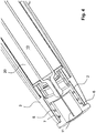
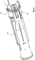
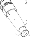
- the distal end of the needle protecting sleeve 2 is arranged with distally directed arms 30, which arms are arranged with radially inwardly extending protrusions 32. These protrusions are arranged to cooperate with a number of ledges 34 on an outer surface of a generally tubular member 36, hereafter named rotator.
- the rotator which is a part or a component of the drive mechanism is connected to the housing such that the rotator is rotatable but prevented to be axially movable in relation to the to the housing.
- the protrusion 32 is positioned at location II in relation to the rotator, Fig. 5 .
- the needle protecting sleeve 2 is moved in the distal direction relative to the device and to the rotator, the protrusion 32 moves along the ledges 34.
- the needle protecting sleeve is rotationally locked to the housing by a guiding mechanism.
- the rotator 36 Since one of the ledges 34 in contact with the protrusion is inclined with respect to the longitudinal axis L, the rotator 36 is forced to turn.
- the needle protecting sleeve 2 subsequently enters its most distal, activating, position, wherein a proximal end surface 38 of the proximal housing part 3 abuts a distally directed ledge portion 40 of the contact member 6, Figs. 3 and 4 , the protrusion 32 is in position VI in relation to the rotator, Fig. 5 .
- penetration and injection triggering means (not shown) which are also part of the drive mechanism are activated.
- the injection device may be triggered in different manners known in the art e.g. by only displacing the needle protecting sleeve towards the distal end in relation to the housing, e.g. the mere turning of the rotator causes the trigger, or by first displacing the needle protecting sleeve towards the distal end in relation to the housing and then operating a trigger member or by first operating a trigger member and then displacing the needle protecting sleeve towards the distal end in relation to the housing.
- the auto-penetration and consecutively the auto-injection are started i.e. a part or a component of the drive mechanism connected to the container holder together with the medicament container move towards the proximal end from a non-delivery position to a delivery position in relation to the needle protecting sleeve and in relation to the rotator until a shoulder 21 of the container holder abuts an edge 22 of the needle protecting sleeve 2, Fig. 3 .
- Said part or component of the drive mechanism connected to the container holder is the locked to the rotator such that the container holder is prevented to be retracted.
- the shoulder 21 may abut an edge of the inner surface of the proximal housing part to avoid a kick back which may otherwise occur when the container holder collides with the edge 22 of the spring-biased needle protecting sleeve.
- the medicament is subsequently delivered through the needle 11.
- different manners to achieve the auto-penetration and auto-injection are known in the art. E.g. the auto-penetration and auto-injection are achieved either through a drive mechanism where only a force from one spring is transferred to move the container together with the container holder and to inject the medicament, or through a drive mechanism where a force from a first spring is transferred to move the container together with the container holder and a force from a second spring is transferred to inject the medicament.
- the needle protecting sleeve spring 5 is strained by a second amount which is dependent on the distance "I", in addition to the first amount which is dependent on the distance "d”. This increases the spring force of the needle protecting sleeve spring 5.
- the needle protrudes proximally beyond the proximal end of the needle protecting sleeve 2 as seen in Figs. 7 and 8 .
- the injection device is removed from the injection site and the needle protecting sleeve 2 is displaced in the proximal direction from its activating position to its end position, Fig. 9 , due to the needle protecting sleeve spring 5 which is biased by the first distance “d” and the second distance “I”, by a force which is greater than the force which was required to shift the needle protecting sleeve 2 by the distance "d” from the initial position.
- the needle protecting sleeve 2 can be shifted in the proximal direction by a distance which is larger than the distance "d” by which the needle protecting sleeve 2 was displaced in the distal direction.
- the needle protecting sleeve 2 is displaced far enough in the proximal direction to its end position wherein its proximal end protrudes proximally beyond the tip of the needle11, Fig. 9 .
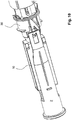
- the protrusion 32 has travelled in the proximal direction along the ledges 34 of the rotator 36 to a position X in relation to the rotator, Fig. 5 .
- the protrusion 32 has passed over a wedge-shaped stop member 42, Fig.
- stop member 42 prevents any subsequent movement of the needle protecting sleeve in the distal direction i.e. from the end position to the activation position.
- other types of locking members may be utilized whereby a locking member of the needle protecting sleeve 2 engages a corresponding locking member of the injection device. In this position i.e. the needle protecting sleeve 2 is in its end position. The needle protecting sleeve 2 is then prevented against moving in the distal direction.
Landscapes
- Health & Medical Sciences (AREA)
- Engineering & Computer Science (AREA)
- Hematology (AREA)
- Anesthesiology (AREA)
- Biomedical Technology (AREA)
- Heart & Thoracic Surgery (AREA)
- Vascular Medicine (AREA)
- Life Sciences & Earth Sciences (AREA)
- Animal Behavior & Ethology (AREA)
- General Health & Medical Sciences (AREA)
- Public Health (AREA)
- Veterinary Medicine (AREA)
- Environmental & Geological Engineering (AREA)
- Infusion, Injection, And Reservoir Apparatuses (AREA)
Claims (9)
- Injektionsvorrichtung mit einem distalen Ende und einem proximalen Ende, umfassend:- ein Gehäuse (1);- eine Nadelschutzhülse (2), welche in Bezug auf das Gehäuse in Längsrichtung bewegbar ist;- eine Behälterhalterung (20), welche in Bezug auf das Gehäuse in Längsrichtung in Richtung des proximalen Endes der Vorrichtung aus einer Nicht-Abgabeposition in eine Abgabeposition bewegbar ist;- eine Nadelschutzhülsen-Feder (5), welche derart operabel zwischen der Nadelschutzhülse (2) und der Behälterhalterung (20) verbunden ist, dass die Nadelschutzhülse (2) in Längsrichtung in Richtung des distalen Endes der Vorrichtung aus einer Anfangsposition in eine Aktivierungsposition und in Richtung des proximalen Endes der Vorrichtung aus der Aktivierungsposition in eine Endposition bewegbar ist; die Nadelschutzhülsen-Feder (5) in einem ersten Maß gespannt wird, wenn sich die Nadelschutzhülse (2) aus ihrer Ausgangsposition in die Aktivierungsposition bewegt, und in einem zweiten Maß gespannt wird, wenn sich die Behälterhalterung (20) aus ihrer Nicht-Abgabeposition in die Abgabeposition bewegt,- dass die Nadelschutzhülsen-Feder (5) operabel zwischen einer distal ausgerichteten Fläche der Nadelschutzhülse (2) und einer proximalen Fläche (21) der Behälterhalterung (20) verbunden ist, dadurch gekennzeichnet, dass eine distal ausgerichtete Stoßkante (22) auf der Nadelschutzhülse (2) so eingerichtet ist, dass sie mit der proximalen Fläche (21) der Behälterhalterung (20) zusammenwirkt, um die Abgabeposition zu definieren.
- Injektionsvorrichtung nach einem der Ansprüche 1 bis 3, wobei die Nadelschutzhülse (2) in ihrer Ausgangsposition proximal um eine vorgegebene Strecke über das proximale Ende des Gehäuses (1) hinausragt.
- Injektionsvorrichtung nach Anspruch 4, wobei die Nadelschutzhülse (2) in ihrer Endposition proximal um eine längere Strecke über das proximale Ende des Gehäuses (1) hinausragt als in ihrer Ausgangsposition.
- Injektionsvorrichtung nach einem der vorhergehenden Ansprüche, wobei in der Endposition der Nadelschutzhülse (2) verhindert wird, dass sie in Längsrichtung in Bezug auf das Gehäuse (1) bewegt wird.
- Injektionsvorrichtung nach einem der vorhergehenden Ansprüche, ferner umfassend einen Medikamentenbehälter (10), welcher eine Nadel (11) und einen Stopper/Kolben (12) aufweist, wobei der Medikamentenbehälter (10) innerhalb der Behälterhalterung (20) angeordnet ist.
- Injektionsvorrichtung nach Anspruch 7, ferner umfassend einen Antriebsmechanismus, durch welchen die Behälterhalterung (20) zusammen mit dem Medikamentenbehälter (10) in Längsrichtung in Bezug auf das Gehäuse (1) in Richtung des proximalen Endes der Vorrichtung aus der Nicht-Abgabeposition in die Abgabeposition bewegbar ist, wenn sich die Nadelschutzhülse (2) in der Aktivierungsposition befindet, so dass die auf dem Medikamentenbehälter (10) angeordnete Nadel (11) in der Abgabeposition über das proximale Ende der Injektionsvorrichtung hinausragt.
- Injektionsvorrichtung nach Anspruch 8, wobei der Antriebsmechanismus mindestens eine Feder umfasst, um die Behälterhalterung zusammen mit dem Medikamentenbehälter in Richtung des proximalen Endes der Vorrichtung zu bewegen und um das Medikament auszustoßen, und wobei die Nadelschutzhülsen-Feder (5), welche operabel zwischen der Nadelschutzhülse und der Behälterhalterung verbunden ist, in dem zweiten Maß gespannt werden kann.
- Injektionsvorrichtung nach Anspruch 9, wobei der Antriebsmechanismus so konfiguriert ist, dass er die mindestens eine Feder in einem vorgespannten Zustand hält.
- Injektionsvorrichtung nach einem der vorhergehenden Ansprüche, wobei das zweite Maß der Spannung größer als das erste Maß der Spannung sein kann.
Applications Claiming Priority (3)
| Application Number | Priority Date | Filing Date | Title |
|---|---|---|---|
| US201261709183P | 2012-10-03 | 2012-10-03 | |
| SE1251113 | 2012-10-03 | ||
| PCT/EP2013/069995 WO2014053378A2 (en) | 2012-10-03 | 2013-09-25 | Medicament delivery device |
Publications (2)
| Publication Number | Publication Date |
|---|---|
| EP2903666A2 EP2903666A2 (de) | 2015-08-12 |
| EP2903666B1 true EP2903666B1 (de) | 2018-12-05 |
Family
ID=50435519
Family Applications (1)
| Application Number | Title | Priority Date | Filing Date |
|---|---|---|---|
| EP13785364.4A Active EP2903666B1 (de) | 2012-10-03 | 2013-09-25 | Vorrichtung zur medikamentenverabreichung |
Country Status (5)
| Country | Link |
|---|---|
| US (1) | US9802005B2 (de) |
| EP (1) | EP2903666B1 (de) |
| CN (1) | CN104768593B (de) |
| TW (1) | TWI566800B (de) |
| WO (1) | WO2014053378A2 (de) |
Families Citing this family (15)
| Publication number | Priority date | Publication date | Assignee | Title |
|---|---|---|---|---|
| USD808010S1 (en) * | 2012-04-20 | 2018-01-16 | Amgen Inc. | Injection device |
| FR3019748A1 (fr) * | 2014-04-11 | 2015-10-16 | Aptar France Sas | Autoinjecteur |
| CN107249666B (zh) * | 2015-01-16 | 2020-10-23 | 贝克顿迪金森法国 | 用于预填充容器的药品储存和分配系统 |
| EP3216472A1 (de) * | 2016-03-11 | 2017-09-13 | Carebay Europe Ltd. | Elektrische informationsvorrichtung zur informationsmitteilung in zusammenhang mit einer medikamentenabgabe |
| EP3146856B1 (de) * | 2016-09-06 | 2022-03-16 | Fontem Holdings 1 B.V. | Spritzennachfüller für eine elektronische rauchvorrichtung |
| FR3056915B1 (fr) * | 2016-10-04 | 2021-12-17 | Aptar France Sas | Dispositif d'injection manuelle. |
| JP7184910B2 (ja) * | 2018-02-16 | 2022-12-06 | ベクトン ディキンソン フランス | 医薬品組成物で充填された医療用容器を支持するための医療用注射デバイス |
| CN109172946B (zh) * | 2018-08-31 | 2023-10-03 | 嘉兴森迈医疗科技有限公司 | 自动注射笔 |
| CN110404139B (zh) * | 2019-05-22 | 2024-07-16 | 嘉兴森迈医疗科技有限公司 | 医用注射装置 |
| CN114423475B (zh) * | 2019-09-30 | 2024-03-26 | 美国安进公司 | 药物递送装置和用于递送药物的方法 |
| WO2021078608A1 (en) * | 2019-10-23 | 2021-04-29 | Becton Dickinson France | Injection device comprising a needle shield |
| WO2021094047A1 (en) * | 2019-11-11 | 2021-05-20 | Shl Medical Ag | Medicament delivery device |
| EP4021537A1 (de) * | 2019-11-19 | 2022-07-06 | E3D A.C.A.L | Automatische notfallinjektionsvorrichtung |
| WO2021244829A1 (en) * | 2020-06-03 | 2021-12-09 | Shl Medical Ag | Safety device for a medicament delivery device |
| WO2025146395A1 (en) * | 2024-01-03 | 2025-07-10 | Shl Medical Ag | Medicament delivery device and medicament delivery assembly |
Family Cites Families (16)
| Publication number | Priority date | Publication date | Assignee | Title |
|---|---|---|---|---|
| US5085641A (en) * | 1989-07-17 | 1992-02-04 | Survival Technology, Inc. | Conveniently carried frequent use auto-injector with improved cap structure |
| AU1860697A (en) * | 1995-09-08 | 1997-07-28 | Visionary Medical Products Corporation | Pen-type injector drive mechanism |
| SE518981C2 (sv) | 2000-12-14 | 2002-12-17 | Shl Medical Ab | Autoinjektor |
| US20030105430A1 (en) | 2001-11-30 | 2003-06-05 | Elan Pharma International Limited Wil House | Automatic injector |
| GB2410188B (en) * | 2004-01-23 | 2006-01-25 | Medical House Plc | Injection device |
| US7449012B2 (en) * | 2004-08-06 | 2008-11-11 | Meridian Medical Technologies, Inc. | Automatic injector |
| US8048035B2 (en) | 2004-08-06 | 2011-11-01 | Meridian Medical Technologies, Inc. | Automatic injector with needle cover |
| GB0601309D0 (en) * | 2006-01-23 | 2006-03-01 | Medical House The Plc | Injection device |
| FR2899482A1 (fr) * | 2006-04-11 | 2007-10-12 | Becton Dickinson France Soc Pa | Dispositif d'injection automatique |
| WO2009040602A1 (en) * | 2007-09-25 | 2009-04-02 | Becton Dickinson France | Autoinject0r with deactivating means moveable by a safety shield |
| EP2536458B1 (de) * | 2010-02-18 | 2017-10-25 | Sanofi-Aventis Deutschland GmbH | Kupplungsmechanismus |
| CA2790280A1 (en) * | 2010-02-22 | 2011-08-25 | Sanofi-Aventis Deutschland Gmbh | Auto - injector with needle shroud and needle protection cap |
| EP2399627A1 (de) * | 2010-06-28 | 2011-12-28 | Sanofi-Aventis Deutschland GmbH | Automatischer Injektor |
| US20120101475A1 (en) * | 2010-10-21 | 2012-04-26 | Meridian Medical Technologies, Inc. | High Efficiency Auto-Injector |
| MX348444B (es) | 2011-08-31 | 2017-06-12 | Shl Group Ab | Dispositivo de inyección. |
| EP2596826A1 (de) | 2011-11-24 | 2013-05-29 | Sanofi-Aventis Deutschland GmbH | Sicherheitsspritze |
-
2013
- 2013-09-25 US US14/432,266 patent/US9802005B2/en active Active
- 2013-09-25 WO PCT/EP2013/069995 patent/WO2014053378A2/en not_active Ceased
- 2013-09-25 EP EP13785364.4A patent/EP2903666B1/de active Active
- 2013-09-25 CN CN201380057034.8A patent/CN104768593B/zh not_active Expired - Fee Related
- 2013-09-30 TW TW102135336A patent/TWI566800B/zh not_active IP Right Cessation
Non-Patent Citations (1)
| Title |
|---|
| None * |
Also Published As
| Publication number | Publication date |
|---|---|
| US9802005B2 (en) | 2017-10-31 |
| EP2903666A2 (de) | 2015-08-12 |
| TW201424786A (zh) | 2014-07-01 |
| CN104768593B (zh) | 2017-08-15 |
| US20150273160A1 (en) | 2015-10-01 |
| WO2014053378A2 (en) | 2014-04-10 |
| CN104768593A (zh) | 2015-07-08 |
| TWI566800B (zh) | 2017-01-21 |
| WO2014053378A3 (en) | 2014-07-31 |
Similar Documents
| Publication | Publication Date | Title |
|---|---|---|
| US9802005B2 (en) | Medicament delivery device | |
| US20240207521A1 (en) | Automatic injection device for administering a fixed dose | |
| US8043262B2 (en) | Injection device with controlled needle retraction | |
| AU2006310971B2 (en) | Autoinjector activation triggering element | |
| US8398594B2 (en) | Spring arrangement in an injection device | |
| AU2006310972B2 (en) | Automatic injector sequence control for a container replacement | |
| DK2745866T3 (en) | Release safety device for an auto-injector | |
| EP2665503B1 (de) | Vorrichtung zur medikamentenverabreichung | |
| CN110325234B (zh) | 医疗输送装置的安全组件 | |
| EP2902058B1 (de) | Injektionsvorrichtung | |
| US11547809B2 (en) | Medicament delivery device | |
| EP2640449B1 (de) | Vorrichtung zur medikamentenverabreichung | |
| EP2624882B1 (de) | Blockier- und rückhaltemechanismus für die nadelschutzhülle einer injektionsnadel | |
| US9155836B2 (en) | Injection device with a spring for a needle protecting sleeve | |
| US11065387B2 (en) | Activation mechanism for a medicament delivery device and a medicament delivery device using the activation mechanism | |
| EP3463513B1 (de) | Medikamentenverabreichungsvorrichtung | |
| US20240350734A1 (en) | A method of assembling a medicament delivery device |
Legal Events
| Date | Code | Title | Description |
|---|---|---|---|
| PUAI | Public reference made under article 153(3) epc to a published international application that has entered the european phase |
Free format text: ORIGINAL CODE: 0009012 |
|
| 17P | Request for examination filed |
Effective date: 20150416 |
|
| AK | Designated contracting states |
Kind code of ref document: A2 Designated state(s): AL AT BE BG CH CY CZ DE DK EE ES FI FR GB GR HR HU IE IS IT LI LT LU LV MC MK MT NL NO PL PT RO RS SE SI SK SM TR |
|
| AX | Request for extension of the european patent |
Extension state: BA ME |
|
| DAX | Request for extension of the european patent (deleted) | ||
| RAP1 | Party data changed (applicant data changed or rights of an application transferred) |
Owner name: CAREBAY EUROPE LTD. |
|
| REG | Reference to a national code |
Ref country code: DE Ref legal event code: R079 Ref document number: 602013047859 Country of ref document: DE Free format text: PREVIOUS MAIN CLASS: A61M0005200000 Ipc: A61M0005310000 |
|
| GRAP | Despatch of communication of intention to grant a patent |
Free format text: ORIGINAL CODE: EPIDOSNIGR1 |
|
| STAA | Information on the status of an ep patent application or granted ep patent |
Free format text: STATUS: GRANT OF PATENT IS INTENDED |
|
| RIC1 | Information provided on ipc code assigned before grant |
Ipc: A61M 5/20 20060101ALI20180622BHEP Ipc: A61M 5/32 20060101ALI20180622BHEP Ipc: A61M 5/31 20060101AFI20180622BHEP Ipc: A61M 5/28 20060101ALI20180622BHEP |
|
| INTG | Intention to grant announced |
Effective date: 20180712 |
|
| GRAS | Grant fee paid |
Free format text: ORIGINAL CODE: EPIDOSNIGR3 |
|
| GRAA | (expected) grant |
Free format text: ORIGINAL CODE: 0009210 |
|
| STAA | Information on the status of an ep patent application or granted ep patent |
Free format text: STATUS: THE PATENT HAS BEEN GRANTED |
|
| RAP1 | Party data changed (applicant data changed or rights of an application transferred) |
Owner name: SHL MEDICAL AG |
|
| AK | Designated contracting states |
Kind code of ref document: B1 Designated state(s): AL AT BE BG CH CY CZ DE DK EE ES FI FR GB GR HR HU IE IS IT LI LT LU LV MC MK MT NL NO PL PT RO RS SE SI SK SM TR |
|
| REG | Reference to a national code |
Ref country code: GB Ref legal event code: FG4D |
|
| REG | Reference to a national code |
Ref country code: CH Ref legal event code: EP |
|
| REG | Reference to a national code |
Ref country code: AT Ref legal event code: REF Ref document number: 1072276 Country of ref document: AT Kind code of ref document: T Effective date: 20181215 |
|
| REG | Reference to a national code |
Ref country code: IE Ref legal event code: FG4D |
|
| REG | Reference to a national code |
Ref country code: DE Ref legal event code: R096 Ref document number: 602013047859 Country of ref document: DE |
|
| REG | Reference to a national code |
Ref country code: NL Ref legal event code: MP Effective date: 20181205 |
|
| REG | Reference to a national code |
Ref country code: AT Ref legal event code: MK05 Ref document number: 1072276 Country of ref document: AT Kind code of ref document: T Effective date: 20181205 |
|
| REG | Reference to a national code |
Ref country code: LT Ref legal event code: MG4D |
|
| PG25 | Lapsed in a contracting state [announced via postgrant information from national office to epo] |
Ref country code: FI Free format text: LAPSE BECAUSE OF FAILURE TO SUBMIT A TRANSLATION OF THE DESCRIPTION OR TO PAY THE FEE WITHIN THE PRESCRIBED TIME-LIMIT Effective date: 20181205 Ref country code: LV Free format text: LAPSE BECAUSE OF FAILURE TO SUBMIT A TRANSLATION OF THE DESCRIPTION OR TO PAY THE FEE WITHIN THE PRESCRIBED TIME-LIMIT Effective date: 20181205 Ref country code: LT Free format text: LAPSE BECAUSE OF FAILURE TO SUBMIT A TRANSLATION OF THE DESCRIPTION OR TO PAY THE FEE WITHIN THE PRESCRIBED TIME-LIMIT Effective date: 20181205 Ref country code: HR Free format text: LAPSE BECAUSE OF FAILURE TO SUBMIT A TRANSLATION OF THE DESCRIPTION OR TO PAY THE FEE WITHIN THE PRESCRIBED TIME-LIMIT Effective date: 20181205 Ref country code: BG Free format text: LAPSE BECAUSE OF FAILURE TO SUBMIT A TRANSLATION OF THE DESCRIPTION OR TO PAY THE FEE WITHIN THE PRESCRIBED TIME-LIMIT Effective date: 20190305 Ref country code: ES Free format text: LAPSE BECAUSE OF FAILURE TO SUBMIT A TRANSLATION OF THE DESCRIPTION OR TO PAY THE FEE WITHIN THE PRESCRIBED TIME-LIMIT Effective date: 20181205 Ref country code: AT Free format text: LAPSE BECAUSE OF FAILURE TO SUBMIT A TRANSLATION OF THE DESCRIPTION OR TO PAY THE FEE WITHIN THE PRESCRIBED TIME-LIMIT Effective date: 20181205 Ref country code: NO Free format text: LAPSE BECAUSE OF FAILURE TO SUBMIT A TRANSLATION OF THE DESCRIPTION OR TO PAY THE FEE WITHIN THE PRESCRIBED TIME-LIMIT Effective date: 20190305 |
|
| PG25 | Lapsed in a contracting state [announced via postgrant information from national office to epo] |
Ref country code: RS Free format text: LAPSE BECAUSE OF FAILURE TO SUBMIT A TRANSLATION OF THE DESCRIPTION OR TO PAY THE FEE WITHIN THE PRESCRIBED TIME-LIMIT Effective date: 20181205 Ref country code: GR Free format text: LAPSE BECAUSE OF FAILURE TO SUBMIT A TRANSLATION OF THE DESCRIPTION OR TO PAY THE FEE WITHIN THE PRESCRIBED TIME-LIMIT Effective date: 20190306 Ref country code: SE Free format text: LAPSE BECAUSE OF FAILURE TO SUBMIT A TRANSLATION OF THE DESCRIPTION OR TO PAY THE FEE WITHIN THE PRESCRIBED TIME-LIMIT Effective date: 20181205 Ref country code: AL Free format text: LAPSE BECAUSE OF FAILURE TO SUBMIT A TRANSLATION OF THE DESCRIPTION OR TO PAY THE FEE WITHIN THE PRESCRIBED TIME-LIMIT Effective date: 20181205 |
|
| PG25 | Lapsed in a contracting state [announced via postgrant information from national office to epo] |
Ref country code: NL Free format text: LAPSE BECAUSE OF FAILURE TO SUBMIT A TRANSLATION OF THE DESCRIPTION OR TO PAY THE FEE WITHIN THE PRESCRIBED TIME-LIMIT Effective date: 20181205 |
|
| PG25 | Lapsed in a contracting state [announced via postgrant information from national office to epo] |
Ref country code: PT Free format text: LAPSE BECAUSE OF FAILURE TO SUBMIT A TRANSLATION OF THE DESCRIPTION OR TO PAY THE FEE WITHIN THE PRESCRIBED TIME-LIMIT Effective date: 20190405 Ref country code: IT Free format text: LAPSE BECAUSE OF FAILURE TO SUBMIT A TRANSLATION OF THE DESCRIPTION OR TO PAY THE FEE WITHIN THE PRESCRIBED TIME-LIMIT Effective date: 20181205 Ref country code: CZ Free format text: LAPSE BECAUSE OF FAILURE TO SUBMIT A TRANSLATION OF THE DESCRIPTION OR TO PAY THE FEE WITHIN THE PRESCRIBED TIME-LIMIT Effective date: 20181205 Ref country code: PL Free format text: LAPSE BECAUSE OF FAILURE TO SUBMIT A TRANSLATION OF THE DESCRIPTION OR TO PAY THE FEE WITHIN THE PRESCRIBED TIME-LIMIT Effective date: 20181205 |
|
| PG25 | Lapsed in a contracting state [announced via postgrant information from national office to epo] |
Ref country code: SM Free format text: LAPSE BECAUSE OF FAILURE TO SUBMIT A TRANSLATION OF THE DESCRIPTION OR TO PAY THE FEE WITHIN THE PRESCRIBED TIME-LIMIT Effective date: 20181205 Ref country code: EE Free format text: LAPSE BECAUSE OF FAILURE TO SUBMIT A TRANSLATION OF THE DESCRIPTION OR TO PAY THE FEE WITHIN THE PRESCRIBED TIME-LIMIT Effective date: 20181205 Ref country code: SK Free format text: LAPSE BECAUSE OF FAILURE TO SUBMIT A TRANSLATION OF THE DESCRIPTION OR TO PAY THE FEE WITHIN THE PRESCRIBED TIME-LIMIT Effective date: 20181205 Ref country code: RO Free format text: LAPSE BECAUSE OF FAILURE TO SUBMIT A TRANSLATION OF THE DESCRIPTION OR TO PAY THE FEE WITHIN THE PRESCRIBED TIME-LIMIT Effective date: 20181205 Ref country code: IS Free format text: LAPSE BECAUSE OF FAILURE TO SUBMIT A TRANSLATION OF THE DESCRIPTION OR TO PAY THE FEE WITHIN THE PRESCRIBED TIME-LIMIT Effective date: 20190405 |
|
| REG | Reference to a national code |
Ref country code: DE Ref legal event code: R097 Ref document number: 602013047859 Country of ref document: DE |
|
| PLBE | No opposition filed within time limit |
Free format text: ORIGINAL CODE: 0009261 |
|
| STAA | Information on the status of an ep patent application or granted ep patent |
Free format text: STATUS: NO OPPOSITION FILED WITHIN TIME LIMIT |
|
| PG25 | Lapsed in a contracting state [announced via postgrant information from national office to epo] |
Ref country code: SI Free format text: LAPSE BECAUSE OF FAILURE TO SUBMIT A TRANSLATION OF THE DESCRIPTION OR TO PAY THE FEE WITHIN THE PRESCRIBED TIME-LIMIT Effective date: 20181205 Ref country code: DK Free format text: LAPSE BECAUSE OF FAILURE TO SUBMIT A TRANSLATION OF THE DESCRIPTION OR TO PAY THE FEE WITHIN THE PRESCRIBED TIME-LIMIT Effective date: 20181205 |
|
| 26N | No opposition filed |
Effective date: 20190906 |
|
| PG25 | Lapsed in a contracting state [announced via postgrant information from national office to epo] |
Ref country code: TR Free format text: LAPSE BECAUSE OF FAILURE TO SUBMIT A TRANSLATION OF THE DESCRIPTION OR TO PAY THE FEE WITHIN THE PRESCRIBED TIME-LIMIT Effective date: 20181205 |
|
| PG25 | Lapsed in a contracting state [announced via postgrant information from national office to epo] |
Ref country code: MC Free format text: LAPSE BECAUSE OF FAILURE TO SUBMIT A TRANSLATION OF THE DESCRIPTION OR TO PAY THE FEE WITHIN THE PRESCRIBED TIME-LIMIT Effective date: 20181205 |
|
| PG25 | Lapsed in a contracting state [announced via postgrant information from national office to epo] |
Ref country code: LU Free format text: LAPSE BECAUSE OF NON-PAYMENT OF DUE FEES Effective date: 20190925 Ref country code: IE Free format text: LAPSE BECAUSE OF NON-PAYMENT OF DUE FEES Effective date: 20190925 |
|
| REG | Reference to a national code |
Ref country code: BE Ref legal event code: MM Effective date: 20190930 |
|
| PG25 | Lapsed in a contracting state [announced via postgrant information from national office to epo] |
Ref country code: BE Free format text: LAPSE BECAUSE OF NON-PAYMENT OF DUE FEES Effective date: 20190930 |
|
| PG25 | Lapsed in a contracting state [announced via postgrant information from national office to epo] |
Ref country code: CY Free format text: LAPSE BECAUSE OF FAILURE TO SUBMIT A TRANSLATION OF THE DESCRIPTION OR TO PAY THE FEE WITHIN THE PRESCRIBED TIME-LIMIT Effective date: 20181205 |
|
| PG25 | Lapsed in a contracting state [announced via postgrant information from national office to epo] |
Ref country code: MT Free format text: LAPSE BECAUSE OF FAILURE TO SUBMIT A TRANSLATION OF THE DESCRIPTION OR TO PAY THE FEE WITHIN THE PRESCRIBED TIME-LIMIT Effective date: 20181205 Ref country code: HU Free format text: LAPSE BECAUSE OF FAILURE TO SUBMIT A TRANSLATION OF THE DESCRIPTION OR TO PAY THE FEE WITHIN THE PRESCRIBED TIME-LIMIT; INVALID AB INITIO Effective date: 20130925 |
|
| PG25 | Lapsed in a contracting state [announced via postgrant information from national office to epo] |
Ref country code: MK Free format text: LAPSE BECAUSE OF FAILURE TO SUBMIT A TRANSLATION OF THE DESCRIPTION OR TO PAY THE FEE WITHIN THE PRESCRIBED TIME-LIMIT Effective date: 20181205 |
|
| P01 | Opt-out of the competence of the unified patent court (upc) registered |
Effective date: 20230425 |
|
| REG | Reference to a national code |
Ref country code: CH Ref legal event code: U11 Free format text: ST27 STATUS EVENT CODE: U-0-0-U10-U11 (AS PROVIDED BY THE NATIONAL OFFICE) Effective date: 20251001 |
|
| PGFP | Annual fee paid to national office [announced via postgrant information from national office to epo] |
Ref country code: DE Payment date: 20250926 Year of fee payment: 13 |
|
| PGFP | Annual fee paid to national office [announced via postgrant information from national office to epo] |
Ref country code: GB Payment date: 20250923 Year of fee payment: 13 |
|
| PGFP | Annual fee paid to national office [announced via postgrant information from national office to epo] |
Ref country code: FR Payment date: 20250925 Year of fee payment: 13 |
|
| PGFP | Annual fee paid to national office [announced via postgrant information from national office to epo] |
Ref country code: CH Payment date: 20251001 Year of fee payment: 13 |