EP2903719B1 - Procédé et dispositif d'extraction d'un gaz à partir d'un mélange de gaz à l'aide d'un éjecteur venturi - Google Patents
Procédé et dispositif d'extraction d'un gaz à partir d'un mélange de gaz à l'aide d'un éjecteur venturi Download PDFInfo
- Publication number
- EP2903719B1 EP2903719B1 EP13783223.4A EP13783223A EP2903719B1 EP 2903719 B1 EP2903719 B1 EP 2903719B1 EP 13783223 A EP13783223 A EP 13783223A EP 2903719 B1 EP2903719 B1 EP 2903719B1
- Authority
- EP
- European Patent Office
- Prior art keywords
- gas
- sorption medium
- reservoir
- additional
- liquid
- Prior art date
- Legal status (The legal status is an assumption and is not a legal conclusion. Google has not performed a legal analysis and makes no representation as to the accuracy of the status listed.)
- Active
Links
Images


Classifications
-
- B—PERFORMING OPERATIONS; TRANSPORTING
- B01—PHYSICAL OR CHEMICAL PROCESSES OR APPARATUS IN GENERAL
- B01D—SEPARATION
- B01D53/00—Separation of gases or vapours; Recovering vapours of volatile solvents from gases; Chemical or biological purification of waste gases, e.g. engine exhaust gases, smoke, fumes, flue gases, aerosols
- B01D53/14—Separation of gases or vapours; Recovering vapours of volatile solvents from gases; Chemical or biological purification of waste gases, e.g. engine exhaust gases, smoke, fumes, flue gases, aerosols by absorption
-
- B—PERFORMING OPERATIONS; TRANSPORTING
- B01—PHYSICAL OR CHEMICAL PROCESSES OR APPARATUS IN GENERAL
- B01D—SEPARATION
- B01D53/00—Separation of gases or vapours; Recovering vapours of volatile solvents from gases; Chemical or biological purification of waste gases, e.g. engine exhaust gases, smoke, fumes, flue gases, aerosols
- B01D53/14—Separation of gases or vapours; Recovering vapours of volatile solvents from gases; Chemical or biological purification of waste gases, e.g. engine exhaust gases, smoke, fumes, flue gases, aerosols by absorption
- B01D53/1425—Regeneration of liquid absorbents
-
- B—PERFORMING OPERATIONS; TRANSPORTING
- B01—PHYSICAL OR CHEMICAL PROCESSES OR APPARATUS IN GENERAL
- B01D—SEPARATION
- B01D53/00—Separation of gases or vapours; Recovering vapours of volatile solvents from gases; Chemical or biological purification of waste gases, e.g. engine exhaust gases, smoke, fumes, flue gases, aerosols
- B01D53/14—Separation of gases or vapours; Recovering vapours of volatile solvents from gases; Chemical or biological purification of waste gases, e.g. engine exhaust gases, smoke, fumes, flue gases, aerosols by absorption
- B01D53/1456—Removing acid components
- B01D53/1468—Removing hydrogen sulfide
-
- B—PERFORMING OPERATIONS; TRANSPORTING
- B01—PHYSICAL OR CHEMICAL PROCESSES OR APPARATUS IN GENERAL
- B01D—SEPARATION
- B01D53/00—Separation of gases or vapours; Recovering vapours of volatile solvents from gases; Chemical or biological purification of waste gases, e.g. engine exhaust gases, smoke, fumes, flue gases, aerosols
- B01D53/14—Separation of gases or vapours; Recovering vapours of volatile solvents from gases; Chemical or biological purification of waste gases, e.g. engine exhaust gases, smoke, fumes, flue gases, aerosols by absorption
- B01D53/1456—Removing acid components
- B01D53/1475—Removing carbon dioxide
-
- B—PERFORMING OPERATIONS; TRANSPORTING
- B01—PHYSICAL OR CHEMICAL PROCESSES OR APPARATUS IN GENERAL
- B01D—SEPARATION
- B01D53/00—Separation of gases or vapours; Recovering vapours of volatile solvents from gases; Chemical or biological purification of waste gases, e.g. engine exhaust gases, smoke, fumes, flue gases, aerosols
- B01D53/14—Separation of gases or vapours; Recovering vapours of volatile solvents from gases; Chemical or biological purification of waste gases, e.g. engine exhaust gases, smoke, fumes, flue gases, aerosols by absorption
- B01D53/1493—Selection of liquid materials for use as absorbents
-
- B—PERFORMING OPERATIONS; TRANSPORTING
- B01—PHYSICAL OR CHEMICAL PROCESSES OR APPARATUS IN GENERAL
- B01D—SEPARATION
- B01D53/00—Separation of gases or vapours; Recovering vapours of volatile solvents from gases; Chemical or biological purification of waste gases, e.g. engine exhaust gases, smoke, fumes, flue gases, aerosols
- B01D53/14—Separation of gases or vapours; Recovering vapours of volatile solvents from gases; Chemical or biological purification of waste gases, e.g. engine exhaust gases, smoke, fumes, flue gases, aerosols by absorption
- B01D53/18—Absorbing units; Liquid distributors therefor
-
- B—PERFORMING OPERATIONS; TRANSPORTING
- B01—PHYSICAL OR CHEMICAL PROCESSES OR APPARATUS IN GENERAL
- B01D—SEPARATION
- B01D53/00—Separation of gases or vapours; Recovering vapours of volatile solvents from gases; Chemical or biological purification of waste gases, e.g. engine exhaust gases, smoke, fumes, flue gases, aerosols
- B01D53/26—Drying gases or vapours
- B01D53/263—Drying gases or vapours by absorption
-
- B—PERFORMING OPERATIONS; TRANSPORTING
- B01—PHYSICAL OR CHEMICAL PROCESSES OR APPARATUS IN GENERAL
- B01D—SEPARATION
- B01D53/00—Separation of gases or vapours; Recovering vapours of volatile solvents from gases; Chemical or biological purification of waste gases, e.g. engine exhaust gases, smoke, fumes, flue gases, aerosols
- B01D53/34—Chemical or biological purification of waste gases
- B01D53/46—Removing components of defined structure
- B01D53/48—Sulfur compounds
- B01D53/52—Hydrogen sulfide
- B01D53/526—Mixtures of hydrogen sulfide and carbon dioxide
-
- B—PERFORMING OPERATIONS; TRANSPORTING
- B01—PHYSICAL OR CHEMICAL PROCESSES OR APPARATUS IN GENERAL
- B01D—SEPARATION
- B01D53/00—Separation of gases or vapours; Recovering vapours of volatile solvents from gases; Chemical or biological purification of waste gases, e.g. engine exhaust gases, smoke, fumes, flue gases, aerosols
- B01D53/34—Chemical or biological purification of waste gases
- B01D53/74—General processes for purification of waste gases; Apparatus or devices specially adapted therefor
- B01D53/77—Liquid phase processes
- B01D53/78—Liquid phase processes with gas-liquid contact
-
- B—PERFORMING OPERATIONS; TRANSPORTING
- B01—PHYSICAL OR CHEMICAL PROCESSES OR APPARATUS IN GENERAL
- B01D—SEPARATION
- B01D53/00—Separation of gases or vapours; Recovering vapours of volatile solvents from gases; Chemical or biological purification of waste gases, e.g. engine exhaust gases, smoke, fumes, flue gases, aerosols
- B01D53/34—Chemical or biological purification of waste gases
- B01D53/74—General processes for purification of waste gases; Apparatus or devices specially adapted therefor
- B01D53/80—Semi-solid phase processes, i.e. by using slurries
-
- B—PERFORMING OPERATIONS; TRANSPORTING
- B01—PHYSICAL OR CHEMICAL PROCESSES OR APPARATUS IN GENERAL
- B01D—SEPARATION
- B01D2252/00—Absorbents, i.e. solvents and liquid materials for gas absorption
- B01D2252/20—Organic absorbents
- B01D2252/202—Alcohols or their derivatives
- B01D2252/2021—Methanol
-
- B—PERFORMING OPERATIONS; TRANSPORTING
- B01—PHYSICAL OR CHEMICAL PROCESSES OR APPARATUS IN GENERAL
- B01D—SEPARATION
- B01D2252/00—Absorbents, i.e. solvents and liquid materials for gas absorption
- B01D2252/20—Organic absorbents
- B01D2252/202—Alcohols or their derivatives
- B01D2252/2023—Glycols, diols or their derivatives
-
- B—PERFORMING OPERATIONS; TRANSPORTING
- B01—PHYSICAL OR CHEMICAL PROCESSES OR APPARATUS IN GENERAL
- B01D—SEPARATION
- B01D2252/00—Absorbents, i.e. solvents and liquid materials for gas absorption
- B01D2252/20—Organic absorbents
- B01D2252/202—Alcohols or their derivatives
- B01D2252/2023—Glycols, diols or their derivatives
- B01D2252/2026—Polyethylene glycol, ethers or esters thereof, e.g. Selexol
-
- B—PERFORMING OPERATIONS; TRANSPORTING
- B01—PHYSICAL OR CHEMICAL PROCESSES OR APPARATUS IN GENERAL
- B01D—SEPARATION
- B01D2252/00—Absorbents, i.e. solvents and liquid materials for gas absorption
- B01D2252/20—Organic absorbents
- B01D2252/202—Alcohols or their derivatives
- B01D2252/2023—Glycols, diols or their derivatives
- B01D2252/2028—Polypropylene glycol, ethers or esters thereof
-
- B—PERFORMING OPERATIONS; TRANSPORTING
- B01—PHYSICAL OR CHEMICAL PROCESSES OR APPARATUS IN GENERAL
- B01D—SEPARATION
- B01D2252/00—Absorbents, i.e. solvents and liquid materials for gas absorption
- B01D2252/20—Organic absorbents
- B01D2252/204—Amines
-
- B—PERFORMING OPERATIONS; TRANSPORTING
- B01—PHYSICAL OR CHEMICAL PROCESSES OR APPARATUS IN GENERAL
- B01D—SEPARATION
- B01D2252/00—Absorbents, i.e. solvents and liquid materials for gas absorption
- B01D2252/20—Organic absorbents
- B01D2252/204—Amines
- B01D2252/20494—Amino acids, their salts or derivatives
-
- B—PERFORMING OPERATIONS; TRANSPORTING
- B01—PHYSICAL OR CHEMICAL PROCESSES OR APPARATUS IN GENERAL
- B01D—SEPARATION
- B01D2252/00—Absorbents, i.e. solvents and liquid materials for gas absorption
- B01D2252/30—Ionic liquids and zwitter-ions
-
- B—PERFORMING OPERATIONS; TRANSPORTING
- B01—PHYSICAL OR CHEMICAL PROCESSES OR APPARATUS IN GENERAL
- B01D—SEPARATION
- B01D2252/00—Absorbents, i.e. solvents and liquid materials for gas absorption
- B01D2252/50—Combinations of absorbents
-
- B—PERFORMING OPERATIONS; TRANSPORTING
- B01—PHYSICAL OR CHEMICAL PROCESSES OR APPARATUS IN GENERAL
- B01D—SEPARATION
- B01D2253/00—Adsorbents used in seperation treatment of gases and vapours
- B01D2253/10—Inorganic adsorbents
- B01D2253/112—Metals or metal compounds not provided for in B01D2253/104 or B01D2253/106
- B01D2253/1124—Metal oxides
-
- B—PERFORMING OPERATIONS; TRANSPORTING
- B01—PHYSICAL OR CHEMICAL PROCESSES OR APPARATUS IN GENERAL
- B01D—SEPARATION
- B01D2256/00—Main component in the product gas stream after treatment
- B01D2256/24—Hydrocarbons
- B01D2256/245—Methane
-
- B—PERFORMING OPERATIONS; TRANSPORTING
- B01—PHYSICAL OR CHEMICAL PROCESSES OR APPARATUS IN GENERAL
- B01D—SEPARATION
- B01D2257/00—Components to be removed
- B01D2257/30—Sulfur compounds
- B01D2257/304—Hydrogen sulfide
-
- B—PERFORMING OPERATIONS; TRANSPORTING
- B01—PHYSICAL OR CHEMICAL PROCESSES OR APPARATUS IN GENERAL
- B01D—SEPARATION
- B01D2257/00—Components to be removed
- B01D2257/50—Carbon oxides
- B01D2257/504—Carbon dioxide
-
- B—PERFORMING OPERATIONS; TRANSPORTING
- B01—PHYSICAL OR CHEMICAL PROCESSES OR APPARATUS IN GENERAL
- B01D—SEPARATION
- B01D2257/00—Components to be removed
- B01D2257/80—Water
-
- B—PERFORMING OPERATIONS; TRANSPORTING
- B01—PHYSICAL OR CHEMICAL PROCESSES OR APPARATUS IN GENERAL
- B01D—SEPARATION
- B01D2258/00—Sources of waste gases
- B01D2258/05—Biogas
-
- B—PERFORMING OPERATIONS; TRANSPORTING
- B01—PHYSICAL OR CHEMICAL PROCESSES OR APPARATUS IN GENERAL
- B01D—SEPARATION
- B01D2259/00—Type of treatment
- B01D2259/12—Methods and means for introducing reactants
- B01D2259/124—Liquid reactants
-
- B—PERFORMING OPERATIONS; TRANSPORTING
- B01—PHYSICAL OR CHEMICAL PROCESSES OR APPARATUS IN GENERAL
- B01D—SEPARATION
- B01D53/00—Separation of gases or vapours; Recovering vapours of volatile solvents from gases; Chemical or biological purification of waste gases, e.g. engine exhaust gases, smoke, fumes, flue gases, aerosols
- B01D53/14—Separation of gases or vapours; Recovering vapours of volatile solvents from gases; Chemical or biological purification of waste gases, e.g. engine exhaust gases, smoke, fumes, flue gases, aerosols by absorption
- B01D53/1406—Multiple stage absorption
-
- B—PERFORMING OPERATIONS; TRANSPORTING
- B01—PHYSICAL OR CHEMICAL PROCESSES OR APPARATUS IN GENERAL
- B01D—SEPARATION
- B01D53/00—Separation of gases or vapours; Recovering vapours of volatile solvents from gases; Chemical or biological purification of waste gases, e.g. engine exhaust gases, smoke, fumes, flue gases, aerosols
- B01D53/14—Separation of gases or vapours; Recovering vapours of volatile solvents from gases; Chemical or biological purification of waste gases, e.g. engine exhaust gases, smoke, fumes, flue gases, aerosols by absorption
- B01D53/1456—Removing acid components
-
- Y—GENERAL TAGGING OF NEW TECHNOLOGICAL DEVELOPMENTS; GENERAL TAGGING OF CROSS-SECTIONAL TECHNOLOGIES SPANNING OVER SEVERAL SECTIONS OF THE IPC; TECHNICAL SUBJECTS COVERED BY FORMER USPC CROSS-REFERENCE ART COLLECTIONS [XRACs] AND DIGESTS
- Y02—TECHNOLOGIES OR APPLICATIONS FOR MITIGATION OR ADAPTATION AGAINST CLIMATE CHANGE
- Y02C—CAPTURE, STORAGE, SEQUESTRATION OR DISPOSAL OF GREENHOUSE GASES [GHG]
- Y02C20/00—Capture or disposal of greenhouse gases
- Y02C20/40—Capture or disposal of greenhouse gases of CO2
Definitions
- the present invention relates to a method for extracting a gas from a gas mixture that contains the gas.
- this untreated biogas In order to be able to be used as a natural gas replacement fuel and injected into the natural gas network, this untreated biogas must be purged of the CO 2 as much as necessary.
- the thus purified gas is also called green gas or biomethane because upon combustion it does not contribute to global warming, in contrast to what happens with the combustion of fossil fuels.
- a method is already known by which the untreated biogas is purified by bringing it into contact with a sorption medium in the form of an absorption liquid that has the property of absorbing the CO 2 gas, after which the purified biogas and the liquid sorption medium with the CO 2 sorbed therein can be removed separately.
- a venturi ejector to bring the gas mixture to be purified in contact with a liquid sorption medium that is able to sorb the gas to be extracted from the gas mixture upon contact with the gas mixture in the venturi ejector.
- liquid sorption medium is regenerated by extracting the sorbed CO 2 from it so that the sorption medium can be used again to purify untreated biogas.
- the regeneration is done by heating and requires a lot of energy as the quantity of heat energy needed to regenerate it is proportional to the quantity of CO 2 that must be removed.
- the invention not only relates to the purification of untreated biogas, but more generally to the extraction of a certain gas from a gas mixture.
- Another typical example of this is the drying of moist air or a moist gas, whereby water vapour has to be extracted from the air.
- Dryers are already known that are used for this purpose that operate according to the principle of cold drying or which make use of an absorbing mass through which the air to be dried or gas to be dried is driven.
- WO2011/109359 and DE102009034548 both disclose washing of a gas mixture with a liquid in a venturi ejector.
- the purpose of the present invention is to provide a solution to at least one of the aforementioned and other disadvantages.
- the extraction of the gas to be extracted is done intensively in the case of the regeneration step thanks to the intense frictional contact between the liquid and the gas drawn in.
- the method provides the advantage that the regeneration proceeds efficiently because, due to the formation of very many small droplets, a large contact surface is created between the liquid first sorption medium and the gas, and also the diffusion length of the gas to be extracted in the first sorption medium is very small. Moreover, due to the large speed difference between the droplets and the gas, the gas on the contact surface between the liquid and gas is continually replenished.
- venturi ejector Due to the action of the venturi ejector, during the supply of the liquid enriched first sorption medium an underpressure occurs in the venturi ejector that is utilised to supply the gaseous second sorption medium due to suction and without other means such as a compressor or other supply means being required to this end.
- a separate second venturi ejector with a liquid input and a gas input, whereby the first sorption medium is supplied under pressure to the liquid input of this venturi ejector and the gas mixture to be purified is drawn in via the gas input of this venturi ejector for the contact between the first sorption medium and the gas mixture.
- the pressure of the gas mixture in the first venturi ejector is increased, which helps the gas to be extracted from the gas mixture to be sorbed better by the sorption medium.
- the method is extremely suitable for extracting CO 2 from untreated biogas, whereby the invention means that a large proportion of the CO 2 is removed from the untreated biogas and a relatively pure biomethane is thus obtained, also with an increased pressure with respect to the pressure of the untreated biogas supplied, which is also favourable as an increased pressure is needed for the further purification of the biogas.
- a liquid first sorption medium is used based on a mixture of amines or amine groups containing compounds or salts thereof.
- the ambient air or another (inert) gas is used as a second sorption medium in the regeneration stage. It is known that the ambient air only contains approx. 0.04% CO 2 and thus can sorb a large quantity of CO 2 .
- the method preferably proceeds according to a continuous process whereby the first sorption medium is guided around a circuit, respectively from a first reservoir via a first venturi ejector to a second reservoir to purify the gas mixture that is drawn in by the first venturi ejector, and then further via a second venturi ejector back to the first reservoir, whereby the second sorption medium is drawn in by the second venturi ejector.
- An advantage is that the gas mixture to be treated can be supplied continuously, whereby the first sorption medium is driven around the circuit continuously.
- At least one additional purification is applied in one or more steps, whereby the first sorption fluid originating from the first reservoir at least partially sorbs the gas to be extracted in the additional purification and is then supplied under pressure to the liquid input of the ejector of the first venturi ejector and whereby the at least partially purified gas mixture originating from the second reservoir is further purified in the additional purification and is tapped off from there via a gas output.
- This additional purification preferably makes use of an additional venturi ejector followed by an additional reservoir that are provided in the circuit between the first reservoir and the first venturi ejector, whereby the first sorption fluid from the first reservoir is further pumped through the additional venturi ejector to the additional reservoir, whereby it is mixed with the at least partially purified gas originating from the second reservoir whose gas output is connected to the gas input of the additional venturi ejector, and whereby the further purified gas is tapped off from the additional reservoir via a gas output, which leads to a high efficiency of the additional purification.
- the regeneration can be done in a number of successive steps with a favourable effect.
- the invention also relates to a device for extracting a gas from a gas mixture by contact with a liquid first sorption medium that can at least partially sorb the gas to be extracted from the gas mixture upon contact with the gas mixture whereby an enriched first sorption medium is formed
- the device comprises a circuit in which the liquid first sorption medium is driven around from a first reservoir through a purification stage to a second reservoir, also part of the device, and from there through a regeneration stage back to the first reservoir, whereby the purification stage is equipped to bring the gas mixture into contact with the first sorption medium, while the regeneration stage is equipped to bring the enriched first sorption medium originating from the purification stage into contact with a gaseous second sorption medium that, upon contact, can at least partially extract the gas to be extracted from the enriched liquid first sorption medium, whereby the regeneration stage comprises a venturi ejector with a liquid input connected to the second reservoir for the supply of the enriched liquid first sorption medium and a gas input for the supply of the gaseous second sorption medium and
- the device enables the advantages of the method according to the invention described above to be realised with relatively simple means.
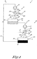
- the device 1 shown in figure 1 concerns a device for extracting a gas from a gas mixture that is supplied by a supply pipe 2.
- the device 1 comprises a circuit 3 to which the supply pipe 2 is connected and in which a liquid first sorption medium circulates from a first reservoir 4 via a first pipe 5 through a second reservoir 6 and via a second pipe back to the first reservoir 4 in the flow direction of the arrow P.
- This first sorption medium presents the property that it can sorb the gas to be extracted from the gas mixture, for example by absorption or adsorption, when it is brought into contact with this gas mixture, whereby for example the partial pressure of the gas to be extracted in the first sorption medium is lower than the partial pressure of the gas to be extracted in the gas mixture.
- the aforementioned circuit 3 comprises two successive stages in the flow direction P, respectively a purification stage 8 in which the gas mixture is brought into contact with the first sorption medium from the first reservoir 4 in order to sorb the gas to be extracted, and a regeneration stage 9 in which the enriched liquid first sorption medium from the second reservoir 6 is brought into contact with a gaseous second sorption medium that is supplied via a second supply pipe 10 and which presents the property that it can again extract the gas sorbed in the purification stage 8 by the first sorption medium from this first sorption medium, for example by desorption.
- the second sorption medium is preferably chosen such that the partial pressure of the gas to be extracted in the second sorption medium is lower than the partial pressure of the gas to be extracted in the enriched liquid first sorption medium.
- the purification stage 8 comprises a first pump 11 that pumps the first sorption medium from the first reservoir 4 via the pipe 5 and a first venturi ejector 12 to the second reservoir 6.
- the first venturi ejector 12 is equipped in a known way with an ejector 13 with a liquid input 14 for the liquid sorption medium that is supplied under pressure by the pump 10 from the first reservoir 4 and which is injected by the ejector 13 into a mixing chamber 15 of the venturi ejector 12.
- the mixing chamber 15 is provided with a suction gas input 16 to which the supply pipe 2 of the gas mixture to be treated is connected.
- the venturi ejector 12 defines a flow channel that narrows in the mixing chamber 15 in the flow direction up to a 'venturi' 17 where the flow cross-section of the flow channel is minimum, after which the flow channel again becomes wider ending, via an output 18, in the aforementioned second reservoir 6 above the level 19 of the liquid sorption medium in this reservoir 6.
- the second reservoir 6 is provided with a gas output 20 through which the purified gas mixture can be removed.
- the regeneration stage 9 comprises a second pump 21 that leads the liquid first sorption medium from the second reservoir 6, together with the gas to be extracted sorbed therein, via the second pipe 7 and a second venturi ejector 22 back to the first reservoir 4.
- the second venturi ejector 22 is, analogous to the first venturi ejector 12, equipped with an ejector 23 with a liquid input 24 connected to the pipe 7, a mixing chamber 25, a venturi 26 and an output 27 that leads to the first reservoir 4.
- the mixing chamber 25 is provided with a suction gas input 28 connected to the aforementioned supply pipe 10 of the gaseous second sorption medium.
- a throttle valve 29 is provided, that is preferably adjustable, in the supply pipe 10 of the second sorption medium.
- the device 1 enables the method of the invention to be applied in a simple way, as set out hereinafter.
- the liquid first sorption medium from the reservoir is pumped through the ejector 13 of the venturi ejector 12, such that this first sorption medium is injected under pressure into the mixing chamber 15.
- the gas mixture is drawn in via the supply pipe 2 in a known way, due to the entrainment effect of the injected liquid droplets, and brought into intense contact with the liquid first sorption medium and mixed by the friction between the gas mixture and the first sorption medium.
- the gas to be extracted is extracted from the gas mixture and is sorbed by the first sorption medium whose concentration of sorbed gas to be extracted increases as a result.
- the remaining gas or gas mixture from which at least a part of the gas to be extracted has been removed from the gas mixture is received as a purified or partly purified gas in the second reservoir 6 where it separates naturally from the liquid first sorption medium.
- the purified or partly purified gas at the output 18 of the venturi ejector 12 has a higher pressure than the supplied gas mixture to be purified, such that this gas can be removed separately at an increased pressure via the gas output 20 without the intervention of additional means to increase the pressure.
- the reservoir 6 In view of the increased pressure the reservoir 6 must be constructed as a pressure vessel that can withstand this increased pressure.
- a throttle valve and/or pressure-increasing system can optionally be incorporated in the supply pipe 2 of the gas mixture in order to be able to control and optimise the mix ratio between the gas mixture and the liquid first sorption medium in the first venturi ejector 12.
- the enriched first sorption medium is pumped from the second reservoir 6 to the second ejector 23 and injected into the mixing chamber 25 of the second venturi ejector 22.
- the second sorption medium is drawn in and brought into close contact with the enriched first sorption medium.
- the gas to be extracted is sorbed by the second sorption medium, during a regeneration step in the regeneration stage 9, from the enriched first sorption medium and a poor or depleted first sorption medium remains with a reduced concentration of sorbed gas to be extracted that is received in the reservoir 4, from where it can be used again for a subsequent purification step in the purification stage 8.
- the second sorption medium together with the gas to be extracted sorbed therein is blown out or removed via a gas output 30 from the first reservoir 4 for further processing or usage.
- a circuit 3 is thus obtained in which the liquid first sorption medium circulates continuously and whereby the gas mixture is continuously drawn in and purified in the purification stage 8 by sorption of the gas to be extracted in the first sorption medium, and whereby a second sorption medium is continuously drawn into the regeneration stage 9 in order to regenerate the first sorption medium with the sorbed gas to be extracted into a reusable first sorption medium.
- the efficiency of the purification stage 8 can be further improved by providing the ejector 12 with a connecting piece, not shown in the drawings, between the mixing chamber 15 and output 18 in order to increase the contact time between the gas mixture and the first liquid sorption medium.
- the efficiency of the regeneration stage 9 can be further improved by providing an ejector 22 with a connecting piece, not shown in the drawings, between the mixing chamber 25 and output 27 in order to increase the contact time between the second gaseous sorption medium and the first liquid sorption medium.
- the efficiency of the method can be further improved by cooling the liquid first sorption medium in the case of an exothermic adsorption or absorption of the gas to be sorbed by the first sorption medium, or heated in the case of an endothermic adsorption or absorption, before being guided through the first venturi ejector 12, and this in order to reduce the partial pressure of the gas to be extracted in the first sorption medium.
- the reservoir 6 and reservoir 4 can be provided with additional means to further improve the method, such as a droplet separator.
- the method and device 1 described above can be used advantageously for purifying untreated biogas that is typically a gas mixture of methane and CO 2 , from which CO 2 must be removed to be left with methane that can be used as a fuel to replace natural gas.
- a mixture of water and amine is used as a first sorption medium that circulates in the circuit and which is able to sorb CO 2 from the biogas.
- enriched amine with an increased CO 2 concentration is formed in the second reservoir 6 that is brought into contact in the regeneration stage 9 with a second sorption medium in the form of ambient air that is drawn in from the environment via the supply pipe 10, and which is able to release, by desorption, the CO 2 sorbed from the untreated biogas that is present in the enriched amine of reservoir 6.
- the CO 2 sorbed in the ambient air is then blown out via the gas output 30 together with the ambient air into the environment.
- the efficiency of the purification of biogas can be improved by heating the enriched first sorption medium in the second reservoir 6 or in the pipe 7 for the regeneration step in the regeneration stage 9 and by cooling the depleted first sorption medium in the first reservoir 4 or in the pipe 5 for purification in the purification stage 8.
- a sorption medium such as amino salt can be chosen that is insensitive or less sensitive to oxidation.
- the method can be optimised by experimental and calculated adjustment of the pressures and temperatures, sorption media and similar.
- various chemical liquids or liquid mixtures can be used as a first sorption medium such as amine, amino salts, amino acids and this possibly in different concentrations.
- liquids or liquid mixtures such as methanol, selexol, NMP, and similar can be used as a first sorption medium, as well as hybrid liquids such as sulfinol, amisol, and similar or even new emerging liquids such as ionic liquids.
- the first sorption medium can also be a slurry, in other words a mixture of liquid and solid particles, such as iron particles to extract the sulphur from the biogas present as H 2 S in the biogas by binding with the iron.
- the resulting FeS particles have to be filtered out.
- the method is not limited to the purification of biogases but can also be used with other gases.
- moist air or moist gas that is a gas mixture of dry air and water vapour that can be extracted from the moist air by bringing it into contact, in a purification stage, with a liquid drying agent, such as propylene glycol, that acts as a first liquid sorption medium.
- a liquid drying agent such as propylene glycol
- the regeneration can be done with ambient air as a second sorption medium in a regeneration stage 9. This requires heating and/or throttling of the pressure with the throttle valve 29 as the partial pressure of water in the ambient air is not always low enough.
- This method can be used at higher pressures, for example with compressed air with a pressure of 10 barg (1 Mpa), whereby this compressed air can be dried by application of the invention with propylene glycol, whereby at the same time the pressure of the dried compressed gas can be increased to 11 barg (1.1 Mpa) for example, thanks to the pressure increase in the venturi ejector 12.
- pump 21 can be left out, whereby only pump 11 pumps the first sorption medium 11 around the circuit 3.
- This single pump 11 ensures a sufficient pressure build-up in the reservoir 6 to be able to make use of this higher pressure to drive the first sorption medium from the second reservoir 6 to the first reservoir 4 via the second venturi ejector 22.
- the pressure of 11 barg (1.1 Mpa) in the second reservoir should be sufficient to drive the propylene glycol further downstream through the regeneration stage 9 of the circuit 3 without an extra pump, whereby a slight overpressure or atmospheric pressure remains in the first reservoir 4.
- Figure 2 shows a variant of a device 1 according to the invention whereby two purification stages 8 and 8' are connected in series in the circuit 3, followed by two regeneration stages 9 and 9' connected in series, whereby the first sorption medium is driven around the circuit 3 in liquid form in the flow direction P and whereby the purified gas is guided in the flow direction Q, in counterflow with respect to the flow direction P of the first sorption medium, through the purification stages 8 and 8' because the gas output 20 of the most downstream purification stage 8 is fed back to the gas input 16' of the purification stage 8' located more upstream.
- an additional purification step is applied in the additional purification stage 8' that makes use of an additional venturi ejector 12' followed by an additional reservoir 6' that are provided in the circuit 3 between the regeneration stage or stages 9 and the first venturi ejector 12, whereby the first sorption medium is pumped from the first reservoir 4 or the additional first reservoir 4' through the additional venturi ejector 12' to the additional reservoir 6', and whereby it is mixed with the at least partially purified gas mixture originating from the second reservoir 6 of the purification stage 8 from which the gas output 20 is connected to the gas input 16' of the additional venturi ejector 12', and whereby the further purified gas mixture is tapped off via the gas output 20' of the additional reservoir 6'.
- an additional regeneration stage 9' is used in figure 2 that makes use of an additional venturi ejector 22' followed by an additional first reservoir 4' that are provided in the circuit 5 between the first reservoir 4' and the purification stage or stages 8, whereby the first sorption fluid is pumped with the partly extracted gas to be extracted sorbed therein from the first reservoir 4 through the additional venturi ejector 22' to the additional reservoir 4', and whereby it is mixed with a gaseous second sorption medium whose supply is connected via a throttle valve 29' to the gas input 28' of the additional second venturi ejector 22', and whereby the second sorption medium with the gas to be extracted sorbed therein is blown out or tapped off from the additional reservoir 4' via the gas output 30'.
- the invention not only relates to a gas mixture of only two gases, but that mixtures of more than two gases can be purged of one or more component gases in the same way, either selectively or simultaneously.
- Figure 3 shows another variant of a device 1 according to the invention that differs from the device 1 of figure 1 by the characteristic that the purification stage 8 with the first venturi ejector 12, pump 11 is replaced by a conventional 'gas washing column' 31 that is made up of a vertical closed column 32 in which the gas mixture to be purified is brought into contact with the first sorption medium from the first reservoir 4 via pipe 5 with the aim of extracting the gas to be extracted from the gas mixture, for example by absorption.
- the column 32 is provided with a gas input 33 and a gas output 34, whereby the gas mixture originating from the supply pipe 2 is driven upwards in the vertical direction through the column 32 to the gas output 34 by means of a compressor 35 or similar.
- the liquid first sorption medium is distributed in counterflow at the top of the column 32 by means of a sprayer or atomiser 36 and falls downwards as a rain or mist due to gravity and it is received and collected at the bottom 37 of the column 32, whereby the column 32 as it were acts as a second reservoir 6 from where the enriched first sorption medium is pumped by the pump 21 of the regeneration stage 9 to the second venturi ejector 22 for regeneration as described above.
- first and second venturi ejector is only used to make a distinction between the venturi ejector of the purification stage and the venturi ejector of the regeneration stage and that it is not excluded that only a second venturi ejector can be present without a first venturi ejector being present, as shown in the example of figure 3 .
Landscapes
- Chemical & Material Sciences (AREA)
- Engineering & Computer Science (AREA)
- Analytical Chemistry (AREA)
- General Chemical & Material Sciences (AREA)
- Oil, Petroleum & Natural Gas (AREA)
- Chemical Kinetics & Catalysis (AREA)
- Environmental & Geological Engineering (AREA)
- Health & Medical Sciences (AREA)
- Biomedical Technology (AREA)
- Gas Separation By Absorption (AREA)
- Drying Of Gases (AREA)
Claims (19)
- Procédé pour l'extraction d'un gaz à partir d'un mélange de gaz, caractérisé en ce que le procédé comprend les étapes suivantes dans desquelles:on procure un premier milieu de sorption liquide qui, lors de sa mise en contact avec le mélange de gaz, peut absorber au moins en partie le gaz qui doit être extrait ;- au cours d'une étape de purification, on met ce premier milieu de sorption en contact avec le mélange de gaz en les guidant de manière conjointe à travers un étage de purification (8) pour obtenir le fait que le gaz qui doit être extrait est absorbé au moins en partie à partir du mélange de gaz par le premier milieu de sorption sur base de la mise en contact réciproque, dans le but de rester avec un mélange de gaz purifié qui comprend moins de gaz à extraire et un premier milieu de sorption liquide enrichi dans lequel le gaz qui doit être extrait du mélange de gaz est absorbé au moins en parfie ;- on procure un deuxième milieu de sorption gazeux qui peut extraire au moins en partie le gaz qui doit être extrait à partir du premier milieu de sorption liquide enrichi lors de sa mise en contact avec ce milieu de sorption liquide enrichi ;- au cours d'une étape de régénération, on met ce deuxième milieu de sorption gazeux en contact avec le premier milieu de sorption liquide enrichi que l'on obtient en cours de l'étape de purification susmentionnée en les guidant de manière conjointe à travers un étage de régénération (9), si bien que, sur base de la mise en contact réciproque, le gaz absorbé qui doit être extrait dans le premier milieu de sorption enrichi est absorbé au moins en partie par le deuxième milieu de sorption, et si bien qu'à la sortie (27) de l'étage de régénération (9) on obtient un premier milieu de sorption liquide régénéré au moins en partie qui peut être réutilisé pour une étape de purification ultérieure ;- dans lequel il est fait usage d'un éjecteur Venturi (22) comprenant une entrée de liquide (24) et une entrée de gaz (28) pour l'étape de régénération, le premier milieu de sorption liquide enrichi émanant de l'étape de purification étant alimenté sous pression à l'entrée de liquide (24) de cet éjecteur Venturi (22) et le deuxième milieu de sorption gazeux étant aspiré via l'entrée de gaz (28) de cet éjecteur Venturi (22) pour la mise en contact entre le premier milieu de sorption enrichi et le deuxième milieu de sorption, et dans lequel il est fait usage d'un circuit (3) dans lequel le premier milieu de sorption liquide est guidé à partir d'un premier réservoir (4) à travers l'étage de purification (8) en direction d'un deuxième réservoir (2) qui reçoit le premier milieu de sorption enrichi, à partir duquel il est entraîné à travers l'étage de régénération (9) qui mène au premier réservoir susmentionné (4) qui reçoit le premier milieu de sorption régénéré.
- Procédé selon la revendication 1, caractérisé en ce qu'il est fait usage d'un éjecteur Venturi séparé (12) comprenant une entrée de liquide (14) et une entrée de gaz (16) pour l'étape de purification, dans lequel le premier milieu de sorption est alimenté sous pression à l'entrée de liquide (14) de cet éjecteur Venturi (12) et le mélange de gaz à purifier est aspiré via l'entrée de gaz (2) de cet éjecteur Venturi (12) pour la mise en contact entre le premier milieu de sorption et le mélange de gaz.
- Procédé selon la revendication 2, caractérisé en ce que le procédé est mis en oeuvre conformément à un procédé en continu dans lequel le premier milieu de sorption liquide est guidé dans le circuit (3) à partir du premier réservoir (4) via l'étage de purification (8) et ensuite en retour en direction du premier réservoir (4) via l'étage de régénération (9), d'une manière telle que le mélange de gaz qui doit être purifié est alimenté en continu à l'étage de purification (8) et que le gaz purifié à partir de cet étage de purification (8) est extrait et que le deuxième milieu de sorption gazeux est aspiré en continu via l'entrée de gaz (28) de l'éjecteur Venturi (22) de l'étage de régénération (9).
- Procédé selon l'une quelconque des revendications précédentes, caractérisé en ce que le deuxième milieu de sorption est aspiré via une restriction de l'écoulement (29) réglable ou non par l'éjecteur Venturi (22) de l'étage de régénération (9) afin de réduire la pression partielle du gaz qui doit être extrait, dans le deuxième milieu de sorption.
- Procédé selon l'une quelconque des revendications précédentes, caractérisé en ce que le premier milieu de sorption liquide est chauffé pour une extraction endothermique du gaz qui doit être extrait ou est refroidi pour une extraction exothermique du gaz qui doit être extrait.
- Procédé selon l'une quelconque des revendications précédentes, caractérisé en ce que la pression du mélange de gaz comprenant le gaz qui doit être extrait diffère de la pression du deuxième milieu de sorption gazeux.
- Procédé selon l'une quelconque des revendications précédentes, caractérisé en ce que le mélange de gaz qui doit être purifié est un biogaz non traité dont on doit éliminer par purge le CO2, le H2S ou un autre contaminant.
- Procédé selon la revendication 7, caractérisé en ce que le premier milieu de sorption est un mélange liquide d'une amine plus ou moins concentrée, d'un sel d'amine ou d'un acide aminé.
- Procédé selon l'une quelconque des revendications 7 à 8, caractérisé en ce que le deuxième milieu de sorption est l'air ambiant.
- Procédé selon l'une quelconque des revendications 1 à 7, caractérisé en ce que le mélange de gaz qui doit être purifié est un gaz humide, par exemple de l'air ou du méthane, qui doit être séché, et le premier milieu de sorption est un liquide hygroscopique tel que le propylène glycol.
- Procédé selon l'une quelconque des revendications précédentes, caractérisé en ce qu'on met en oeuvre une purification supplémentaire dans un ou plusieurs étages de purification supplémentaires (8'), dans lequel le premier milieu d'absorption émanant du premier réservoir (4) absorbe au moins en partie le gaz qui doit être extrait au cours de la purification supplémentaire et est ensuite alimenté sous pression à entrée de liquide (14) du premier éjecteur Venturi (12), et dans lequel le mélange de gaz purifié au moins en partie émanant du deuxième réservoir (6) est soumis à une purification ultérieure au cours de la purification supplémentaire et est évacué à partir de là via une sortie (20') pour les gaz.
- Procédé selon la revendication 11, caractérisé en ce que, dans une ou plusieurs étapes de la purification supplémentaire, il est fait usage d'un éjecteur Venturi supplémentaire (12') suivi d'un réservoir supplémentaire (6') qui est prévu dans le circuit (3) entre le premier réservoir (4) et le premier éjecteur Venturi (12), dans lequel le premier milieu de sorption est pompé à partir du premier réservoir (4) à travers l'éjecteur Venturi supplémentaire (12') en direction du réservoir supplémentaire (6'), dans lequel il est mélangé avec le mélange de gaz purifié au moins en partie émanant du deuxième réservoir (6) dont la sortie (20) pour les gaz est raccordée à l'entrée de gaz (16') de l'éjecteur Venturi supplémentaire (12'), et dans lequel le mélange de gaz soumis à une purification ultérieure est évacué via une sortie (20') pour les gaz, du réservoir supplémentaire (6').
- Procédé selon l'une quelconque des revendications précédentes, caractérisé en ce qu'on met en oeuvre une régénération supplémentaire en une ou plusieurs étapes, dans lequel le premier fluide de sorption régénéré en partie émanant du premier réservoir (4) est soumis à une régénération ultérieure dans la régénération supplémentaire et est ensuite alimenté sous pression à l'étage de purification (8) ou à l'étage de purification supplémentaire (8') lorsque ce dernier est prévu.
- Procédé selon la revendication 12, caractérisé en ce que, dans une ou plusieurs étapes de la régénération supplémentaire, il est fait usage d'un éjecteur Venturi supplémentaire (22') suivi d'un réservoir supplémentaire (4'), dans lequel le premier milieu de sorption dans lequel se trouve à l'état absorbé le gaz qui doit être extrait est pompé à partir du premier réservoir (4) à travers l'éjecteur Venturi supplémentaire (22') en direction du réservoir supplémentaire (4'), dans lequel il est mélangé avec un deuxième milieu de sorption gazeux qui est aspiré via l'entrée de gaz (28') de l'éjecteur Venturi supplémentaire (22'), et dans lequel le deuxième milieu de sorption, conjointement avec le gaz absorbé qui doit être extrait, est évacué via une sortie (30') pour les gaz, du réservoir supplémentaire (4').
- Dispositif pour l'extraction d'un gaz à partir d'un mélange de gaz par mise en contact avec un premier milieu de sorption liquide qui peut absorber au moins en partie le gaz qui doit être extrait à partir du mélange de gaz lors de sa mise en contact avec le mélange de gaz, si bien que l'on obtient un premier milieu de sorption enrichi, le dispositif comprenant un circuit (3) dans lequel le premier milieu de sorption liquide est entraîné à partir d'un premier réservoir (4) à travers un étage de purification (8) en direction d'un deuxième réservoir (6), faisant également partie du dispositif, et à partir de là, à travers un étage de régénération (9) et en retour en direction du premier réservoir (4), dans lequel l'étage de purification (8) est équipé de manière à amener le mélange de gaz en contact avec le premier milieu de sorption, tandis que l'étage de régénération est équipé pour amener le premier milieu de sorption enrichi émanant de l'étage de purification, en contact avec un deuxième milieu de sorption gazeux qui, lors de la mise en contact, peut extraire au moins en partie le gaz qui doit être extrait à partir du premier milieu de sorption liquide enrichi, caractérisé en ce que l'étage de régénération (9) comprend un éjecteur Venturi (22) comprenant une entrée de liquide (24) reliée au deuxième réservoir (6) pour l'alimentation du premier milieu de sorption liquide enrichi, et une entrée de gaz (28) pour l'alimentation du deuxième milieu de sorption gazeux, et une sortie de liquide (27) qui mène au premier réservoir (4).
- Dispositif selon la revendication 15, caractérisé en ce que l'étage de purification (8) comprend un éjecteur Venturi séparé (12) comprenant une entrée de liquide (14) qui est reliée au premier réservoir (4) pour l'alimentation du premier milieu de sorption, et une entrée de gaz (2) pour l'alimentation du mélange gazeux qui doit être purifié et une sortie (18) pour le gaz purifié, qui mène au deuxième réservoir (6).
- Dispositif selon la revendication 15 ou 16, caractérisé en ce qu'il comprend au moins une pompe (11 et/ou 21) pour entraîner le premier milieu de sorption dans le circuit (3), de manière plus spécifique, en ce qu'il comprend au moins deux pompes, respectivement une première pompe (11) dans l'étage de purification (8) reliée au premier réservoir (4) via un conduit (5) et qui confère une pression à l'entrée de liquide (14) du premier éjecteur Venturi (12) et une deuxième pompe (21) dans l'étage de nettoyage (9) reliée au deuxième réservoir (6) via un conduit (7) et qui confère une pression à l'entrée de liquide (24) du deuxième éjecteur Venturi (22).
- Dispositif selon l'une quelconque des revendications 16 à 17, caractérisé en ce qu'on prévoit au moins un étage de purification supplémentaire (8') comprenant un éjecteur Venturi supplémentaire (12') suivi d'un réservoir supplémentaire (6') qui sont prévus dans le circuit (3) dans le conduit (5) entre le premier réservoir (4) et le premier éjecteur Venturi (12), la sortie (20) pour les gaz, du deuxième réservoir (6) étant reliée à l'entrée de gaz (16') de l'éjecteur Venturi supplémentaire (12') et la sortie (20') pour les gaz, du réservoir supplémentaire (6') étant équipée pour évacuer le mélange de gaz purifié.
- Dispositif selon l'une quelconque des revendications 16 à 18, caractérisé en ce qu'on prévoit au moins un étage de régénération supplémentaire (9') comprenant un éjecteur Venturi supplémentaire (22') suivi d'un réservoir supplémentaire (4') qui sont prévus dans le circuit (3) entre le premier réservoir (4) et le premier éjecteur Venturi (12), dans lequel le premier fluide de sorption dans lequel est absorbé le gaz qui doit être extrait est pompé à partir du premier réservoir (4) à travers l'éjecteur Venturi supplémentaire (22') en direction du réservoir supplémentaire (4'), dans lequel il est - mélangé avec un deuxième milieu de sorption gazeux qui est aspiré via l'entrée de gaz (28') de l'éjecteur Venturi supplémentaire (22'), et dans lequel le deuxième milieu de sorption conjointement avec le gaz généré soumis à une absorption partielle est évacué via une sortie (30') pour les gaz, du réservoir supplémentaire (4').
Applications Claiming Priority (2)
| Application Number | Priority Date | Filing Date | Title |
|---|---|---|---|
| BE2012/0660A BE1021343B1 (nl) | 2012-10-05 | 2012-10-05 | Werkwijze voor het onttrekken van een gas uit een gasmengsel en inrichting daarbij toegepast. |
| PCT/BE2013/000051 WO2014053030A1 (fr) | 2012-10-05 | 2013-10-01 | Procédé et dispositif d'extraction d'un gaz à partir d'un mélange de gaz à l'aide d'un éjecteur venturi |
Publications (3)
| Publication Number | Publication Date |
|---|---|
| EP2903719A1 EP2903719A1 (fr) | 2015-08-12 |
| EP2903719B1 true EP2903719B1 (fr) | 2017-01-18 |
| EP2903719B8 EP2903719B8 (fr) | 2017-03-29 |
Family
ID=47148541
Family Applications (1)
| Application Number | Title | Priority Date | Filing Date |
|---|---|---|---|
| EP13783223.4A Active EP2903719B8 (fr) | 2012-10-05 | 2013-10-01 | Procédé et dispositif d'extraction d'un gaz à partir d'un mélange de gaz à l'aide d'un éjecteur venturi |
Country Status (10)
| Country | Link |
|---|---|
| US (1) | US10173165B2 (fr) |
| EP (1) | EP2903719B8 (fr) |
| JP (1) | JP6224112B2 (fr) |
| CN (1) | CN105228723B (fr) |
| BE (1) | BE1021343B1 (fr) |
| CA (1) | CA2886197C (fr) |
| DK (1) | DK2903719T3 (fr) |
| ES (1) | ES2620031T3 (fr) |
| RU (1) | RU2605978C2 (fr) |
| WO (1) | WO2014053030A1 (fr) |
Families Citing this family (23)
| Publication number | Priority date | Publication date | Assignee | Title |
|---|---|---|---|---|
| US9757683B1 (en) * | 2008-10-17 | 2017-09-12 | Alchem Environmental Ip Llc | Polyphasic pressurized homogenizer (PPH) and methods for methane purification |
| US9387431B2 (en) | 2014-09-26 | 2016-07-12 | Carollo Engineers, Inc. | Gas scrubber system and method |
| DK3426981T3 (da) | 2016-03-31 | 2022-06-20 | Inventys Thermal Tech Inc | Forbrændingssystem, der inkorporerer gasseparation ved temperatursvingningsadsorption |
| JP6957497B2 (ja) | 2016-03-31 | 2021-11-02 | スヴァンテ インコーポレイテッド | 再生のために蒸気を使用する吸着ガス分離 |
| WO2017165974A1 (fr) | 2016-03-31 | 2017-10-05 | Inventys Thermal Technologies Inc. | Procédé et système de séparation adsorptive de gaz |
| US10850211B2 (en) * | 2016-07-01 | 2020-12-01 | Hach Lange Gmbh | Microfluidic process water analyzer |
| FI129944B (en) * | 2017-05-09 | 2022-11-15 | Teknologian Tutkimuskeskus Vtt Oy | Method and apparatus for pressurizing gas |
| US10974194B2 (en) | 2017-07-18 | 2021-04-13 | Saudi Arabian Oil Company | System for flare gas recovery using gas sweetening process |
| US10981104B2 (en) * | 2018-04-12 | 2021-04-20 | Saudi Arabian Oil Company | System for flare gas recovery using gas sweetening process |
| CN108671705A (zh) * | 2018-06-22 | 2018-10-19 | 江苏昌吉利新能源科技有限公司 | 一种文丘里voc吸收利用装置 |
| FR3085281B1 (fr) * | 2018-09-04 | 2023-01-20 | Alfano Calogero | Procede et installation d'epuration d'un gaz brut par un solvant liquide |
| EP4733683A2 (fr) | 2019-08-16 | 2026-04-29 | Atlas Copco Airpower, naamloze vennootschap | Séchoir pour gaz comprimé, installation de compresseur équipée d'un séchoir et procédé de séchage de gaz comprimé |
| WO2023283099A1 (fr) * | 2021-07-07 | 2023-01-12 | Bechtel Energy Technologies & Solutions, Inc. | Systèmes et procédés pour éliminer le dioxyde de carbone à partir d'un gaz de carneau de combustion et/ou de l'air |
| TR202014690A1 (tr) | 2020-09-16 | 2022-03-21 | Arcelik As | Mi̇kro kabarcik üreteci̇ i̇çeren bi̇r hava temi̇zleme ci̇hazi |
| CN112263894B (zh) * | 2020-11-26 | 2025-03-18 | 西南石油大学 | 一种针对含硫气体的离子液体脱硫方法及设备 |
| JP2023027729A (ja) * | 2021-08-17 | 2023-03-02 | 晴雄 森重 | 重循環水型二酸化炭素分離精製貯蔵システム |
| WO2023008584A1 (fr) * | 2021-07-26 | 2023-02-02 | 晴雄 森重 | Dispositif de récupération de dioxyde de carbone et climatiseur utilisant chacun un effet de tube de pitot |
| CN113941228B (zh) * | 2021-12-22 | 2022-04-19 | 天津木华清研科技有限公司 | 液体喷射器、锂电池生产中的nmp的回收系统及方法 |
| US12233379B2 (en) * | 2022-11-07 | 2025-02-25 | Bentaus, LLC | Carbon capture adapter |
| EP4655082A2 (fr) * | 2023-01-27 | 2025-12-03 | Sustainable Energy Solutions, Inc. | Échangeur de chaleur sensible et séchoir |
| US12005390B1 (en) * | 2023-11-15 | 2024-06-11 | AirMyne, Inc. | Hybrid carbon dioxide removal systems |
| US12274977B1 (en) * | 2024-03-15 | 2025-04-15 | AirMyne, Inc. | Carbon dioxide removal systems using a geothermal heat source |
| CN118698290A (zh) * | 2024-08-29 | 2024-09-27 | 上海天马再生能源有限公司 | 利用垃圾焚烧烟气中二氧化碳降低水硬度的装置及方法 |
Family Cites Families (16)
| Publication number | Priority date | Publication date | Assignee | Title |
|---|---|---|---|---|
| US2127571A (en) * | 1935-08-21 | 1938-08-23 | Du Pont | Absorption of hydrochloric acid in liquids |
| US3648434A (en) * | 1969-02-27 | 1972-03-14 | Maloney Crawford Tank | Glycol regeneration using eductor flash separation |
| JPS5268071A (en) * | 1975-12-03 | 1977-06-06 | Tokyo Gas Co Ltd | Method and apparatus for regenerating absorbing liquids |
| DE2908263A1 (de) * | 1979-03-02 | 1980-09-11 | Hoechst Ag | Verfahren und vorrichtung zur absorption von gasen |
| US4366131A (en) * | 1979-05-31 | 1982-12-28 | Irwin Fox | Highly reactive iron oxide agents and apparatus for hydrogen sulfide scavenging |
| US4828768A (en) * | 1983-06-10 | 1989-05-09 | Chevron Research Company | Jet scrubber and method of operation |
| WO1999013962A1 (fr) * | 1997-09-15 | 1999-03-25 | Den Norske Stats Oljeselskap A.S. | Systeme de separation de fluides |
| US6078420A (en) * | 1998-06-24 | 2000-06-20 | Optical Engineering, Inc. | Hole-coupled laser scanning system |
| RU2206374C2 (ru) * | 2001-06-14 | 2003-06-20 | Федеральное государственное унитарное предприятие "Научно-исследовательский институт Научно-производственное объединение "Луч" | Способ разделения газовой смеси и установка для его осуществления |
| JP2005049041A (ja) * | 2003-07-30 | 2005-02-24 | Dainippon Ink & Chem Inc | 可燃性廃ガス燃焼処理方法 |
| DE102004011427A1 (de) * | 2004-03-09 | 2005-09-29 | Basf Ag | Absorptionsmittel mit verbesserter Oxidationsbeständigkeit und Verfahren zum Entsäuern von Fluidströmen |
| JP5165861B2 (ja) | 2006-06-26 | 2013-03-21 | 昭和電工株式会社 | 過弗化物の処理方法及び処理装置 |
| DE102008060310B4 (de) * | 2008-12-03 | 2013-01-31 | Dge Dr.-Ing. Günther Engineering Gmbh | Verfahren und Anlage zur Reinigung von Roh- oder Biogas zur Gewinnung von Methan |
| DE102009009753B4 (de) * | 2009-02-20 | 2014-01-30 | Mt-Biomethan Gmbh | Verfahren zur chemisorptiven Reinigung von Bio- oder Klärgas |
| DE102009034548A1 (de) * | 2009-07-23 | 2011-04-07 | Hitachi Power Europe Gmbh | Rauchgasreinigung mittels CO2-Strahlwischer |
| US20110217218A1 (en) * | 2010-03-02 | 2011-09-08 | Exxonmobil Research And Engineering Company | Systems and Methods for Acid Gas Removal |
-
2012
- 2012-10-05 BE BE2012/0660A patent/BE1021343B1/nl active
-
2013
- 2013-10-01 JP JP2015534886A patent/JP6224112B2/ja active Active
- 2013-10-01 DK DK13783223.4T patent/DK2903719T3/en active
- 2013-10-01 RU RU2015116638A patent/RU2605978C2/ru active
- 2013-10-01 CN CN201380052257.5A patent/CN105228723B/zh active Active
- 2013-10-01 ES ES13783223.4T patent/ES2620031T3/es active Active
- 2013-10-01 CA CA2886197A patent/CA2886197C/fr active Active
- 2013-10-01 WO PCT/BE2013/000051 patent/WO2014053030A1/fr not_active Ceased
- 2013-10-01 EP EP13783223.4A patent/EP2903719B8/fr active Active
- 2013-10-01 US US14/430,968 patent/US10173165B2/en active Active
Non-Patent Citations (1)
| Title |
|---|
| None * |
Also Published As
| Publication number | Publication date |
|---|---|
| US10173165B2 (en) | 2019-01-08 |
| WO2014053030A1 (fr) | 2014-04-10 |
| BE1021343B1 (nl) | 2015-11-05 |
| ES2620031T3 (es) | 2017-06-27 |
| CA2886197A1 (fr) | 2014-04-10 |
| JP6224112B2 (ja) | 2017-11-01 |
| EP2903719A1 (fr) | 2015-08-12 |
| RU2015116638A (ru) | 2016-11-27 |
| DK2903719T3 (en) | 2017-04-03 |
| EP2903719B8 (fr) | 2017-03-29 |
| CA2886197C (fr) | 2018-06-12 |
| CN105228723A (zh) | 2016-01-06 |
| JP2015535741A (ja) | 2015-12-17 |
| RU2605978C2 (ru) | 2017-01-10 |
| CN105228723B (zh) | 2019-01-08 |
| US20150251129A1 (en) | 2015-09-10 |
Similar Documents
| Publication | Publication Date | Title |
|---|---|---|
| EP2903719B1 (fr) | Procédé et dispositif d'extraction d'un gaz à partir d'un mélange de gaz à l'aide d'un éjecteur venturi | |
| CA2804627C (fr) | Colonne de separation sous pression de gaz et procede pour generer un gaz de produit a haute pression | |
| JP5658243B2 (ja) | Co2吸収剤の再生利用のための方法および再生利用器 | |
| US8899557B2 (en) | In-line device for gas-liquid contacting, and gas processing facility employing co-current contactors | |
| US9919259B2 (en) | Gas pressurized separation column and process to generate a high pressure product gas | |
| AU2014206161B2 (en) | An ammonia stripper for a carbon capture system for reduction of energy consumption | |
| CN107148398A (zh) | 从气态混合物中分离产物气体的方法 | |
| CN101760270B (zh) | 脱除并回收天然气中co2的方法 | |
| AU2015413303A1 (en) | Configurations and methods for processing high pressure acid gases with zero emissions | |
| EP2428264B1 (fr) | Système de déshydratation pour supprimer l'eau d'un gaz | |
| CN104797326B (zh) | 用于通过气体解吸进行热整合液体吸收剂再生的工艺和设备 | |
| US9206795B2 (en) | Process and apparatus for drying and compressing a CO2-rich stream | |
| CN116712838A (zh) | 一种污水处理厂生化反应池废气回收装置及高纯度co2捕集方法 | |
| KR20130137953A (ko) | 송풍장치를 구비한 이산화탄소 포집장치 및 이를 이용한 이산화탄소 포집방법 | |
| RU2381823C1 (ru) | Способ очистки газа от кислых компонентов и установка для его осуществления | |
| US20160166977A1 (en) | Gas-assisted stripping of liquid solvents for carbon capture | |
| CN219897602U (zh) | 一种污水处理厂生化反应池废气回收装置 |
Legal Events
| Date | Code | Title | Description |
|---|---|---|---|
| PUAI | Public reference made under article 153(3) epc to a published international application that has entered the european phase |
Free format text: ORIGINAL CODE: 0009012 |
|
| 17P | Request for examination filed |
Effective date: 20150417 |
|
| AK | Designated contracting states |
Kind code of ref document: A1 Designated state(s): AL AT BE BG CH CY CZ DE DK EE ES FI FR GB GR HR HU IE IS IT LI LT LU LV MC MK MT NL NO PL PT RO RS SE SI SK SM TR |
|
| AX | Request for extension of the european patent |
Extension state: BA ME |
|
| RIN1 | Information on inventor provided before grant (corrected) |
Inventor name: HEIRMAN, PETER JOZEF Inventor name: AALDERINK, GEURT |
|
| DAX | Request for extension of the european patent (deleted) | ||
| GRAP | Despatch of communication of intention to grant a patent |
Free format text: ORIGINAL CODE: EPIDOSNIGR1 |
|
| INTG | Intention to grant announced |
Effective date: 20160916 |
|
| STAA | Information on the status of an ep patent application or granted ep patent |
Free format text: STATUS: GRANT OF PATENT IS INTENDED |
|
| GRAS | Grant fee paid |
Free format text: ORIGINAL CODE: EPIDOSNIGR3 |
|
| GRAA | (expected) grant |
Free format text: ORIGINAL CODE: 0009210 |
|
| STAA | Information on the status of an ep patent application or granted ep patent |
Free format text: STATUS: THE PATENT HAS BEEN GRANTED |
|
| GRAT | Correction requested after decision to grant or after decision to maintain patent in amended form |
Free format text: ORIGINAL CODE: EPIDOSNCDEC |
|
| AK | Designated contracting states |
Kind code of ref document: B1 Designated state(s): AL AT BE BG CH CY CZ DE DK EE ES FI FR GB GR HR HU IE IS IT LI LT LU LV MC MK MT NL NO PL PT RO RS SE SI SK SM TR |
|
| REG | Reference to a national code |
Ref country code: GB Ref legal event code: FG4D |
|
| REG | Reference to a national code |
Ref country code: CH Ref legal event code: EP |
|
| RAP2 | Party data changed (patent owner data changed or rights of a patent transferred) |
Owner name: ATLAS COPCO AIRPOWER, NAAMLOZE VENNOOTSCHAP |
|
| REG | Reference to a national code |
Ref country code: AT Ref legal event code: REF Ref document number: 862576 Country of ref document: AT Kind code of ref document: T Effective date: 20170215 |
|
| REG | Reference to a national code |
Ref country code: IE Ref legal event code: FG4D |
|
| REG | Reference to a national code |
Ref country code: DE Ref legal event code: R096 Ref document number: 602013016786 Country of ref document: DE |
|
| REG | Reference to a national code |
Ref country code: CH Ref legal event code: NV Representative=s name: ORITI PATENTS - FRANCO ORITI, CH |
|
| REG | Reference to a national code |
Ref country code: DK Ref legal event code: T3 Effective date: 20170328 |
|
| REG | Reference to a national code |
Ref country code: SE Ref legal event code: TRGR |
|
| REG | Reference to a national code |
Ref country code: NL Ref legal event code: FP |
|
| REG | Reference to a national code |
Ref country code: LT Ref legal event code: MG4D |
|
| REG | Reference to a national code |
Ref country code: AT Ref legal event code: MK05 Ref document number: 862576 Country of ref document: AT Kind code of ref document: T Effective date: 20170118 |
|
| REG | Reference to a national code |
Ref country code: ES Ref legal event code: FG2A Ref document number: 2620031 Country of ref document: ES Kind code of ref document: T3 Effective date: 20170627 |
|
| PG25 | Lapsed in a contracting state [announced via postgrant information from national office to epo] |
Ref country code: GR Free format text: LAPSE BECAUSE OF FAILURE TO SUBMIT A TRANSLATION OF THE DESCRIPTION OR TO PAY THE FEE WITHIN THE PRESCRIBED TIME-LIMIT Effective date: 20170419 Ref country code: LT Free format text: LAPSE BECAUSE OF FAILURE TO SUBMIT A TRANSLATION OF THE DESCRIPTION OR TO PAY THE FEE WITHIN THE PRESCRIBED TIME-LIMIT Effective date: 20170118 Ref country code: NO Free format text: LAPSE BECAUSE OF FAILURE TO SUBMIT A TRANSLATION OF THE DESCRIPTION OR TO PAY THE FEE WITHIN THE PRESCRIBED TIME-LIMIT Effective date: 20170418 Ref country code: HR Free format text: LAPSE BECAUSE OF FAILURE TO SUBMIT A TRANSLATION OF THE DESCRIPTION OR TO PAY THE FEE WITHIN THE PRESCRIBED TIME-LIMIT Effective date: 20170118 Ref country code: IS Free format text: LAPSE BECAUSE OF FAILURE TO SUBMIT A TRANSLATION OF THE DESCRIPTION OR TO PAY THE FEE WITHIN THE PRESCRIBED TIME-LIMIT Effective date: 20170518 |
|
| PG25 | Lapsed in a contracting state [announced via postgrant information from national office to epo] |
Ref country code: PT Free format text: LAPSE BECAUSE OF FAILURE TO SUBMIT A TRANSLATION OF THE DESCRIPTION OR TO PAY THE FEE WITHIN THE PRESCRIBED TIME-LIMIT Effective date: 20170518 Ref country code: RS Free format text: LAPSE BECAUSE OF FAILURE TO SUBMIT A TRANSLATION OF THE DESCRIPTION OR TO PAY THE FEE WITHIN THE PRESCRIBED TIME-LIMIT Effective date: 20170118 Ref country code: PL Free format text: LAPSE BECAUSE OF FAILURE TO SUBMIT A TRANSLATION OF THE DESCRIPTION OR TO PAY THE FEE WITHIN THE PRESCRIBED TIME-LIMIT Effective date: 20170118 Ref country code: AT Free format text: LAPSE BECAUSE OF FAILURE TO SUBMIT A TRANSLATION OF THE DESCRIPTION OR TO PAY THE FEE WITHIN THE PRESCRIBED TIME-LIMIT Effective date: 20170118 Ref country code: LV Free format text: LAPSE BECAUSE OF FAILURE TO SUBMIT A TRANSLATION OF THE DESCRIPTION OR TO PAY THE FEE WITHIN THE PRESCRIBED TIME-LIMIT Effective date: 20170118 Ref country code: BG Free format text: LAPSE BECAUSE OF FAILURE TO SUBMIT A TRANSLATION OF THE DESCRIPTION OR TO PAY THE FEE WITHIN THE PRESCRIBED TIME-LIMIT Effective date: 20170418 |
|
| REG | Reference to a national code |
Ref country code: FR Ref legal event code: PLFP Year of fee payment: 5 |
|
| REG | Reference to a national code |
Ref country code: DE Ref legal event code: R097 Ref document number: 602013016786 Country of ref document: DE |
|
| PG25 | Lapsed in a contracting state [announced via postgrant information from national office to epo] |
Ref country code: EE Free format text: LAPSE BECAUSE OF FAILURE TO SUBMIT A TRANSLATION OF THE DESCRIPTION OR TO PAY THE FEE WITHIN THE PRESCRIBED TIME-LIMIT Effective date: 20170118 Ref country code: RO Free format text: LAPSE BECAUSE OF FAILURE TO SUBMIT A TRANSLATION OF THE DESCRIPTION OR TO PAY THE FEE WITHIN THE PRESCRIBED TIME-LIMIT Effective date: 20170118 Ref country code: CZ Free format text: LAPSE BECAUSE OF FAILURE TO SUBMIT A TRANSLATION OF THE DESCRIPTION OR TO PAY THE FEE WITHIN THE PRESCRIBED TIME-LIMIT Effective date: 20170118 Ref country code: SK Free format text: LAPSE BECAUSE OF FAILURE TO SUBMIT A TRANSLATION OF THE DESCRIPTION OR TO PAY THE FEE WITHIN THE PRESCRIBED TIME-LIMIT Effective date: 20170118 |
|
| PLBE | No opposition filed within time limit |
Free format text: ORIGINAL CODE: 0009261 |
|
| STAA | Information on the status of an ep patent application or granted ep patent |
Free format text: STATUS: NO OPPOSITION FILED WITHIN TIME LIMIT |
|
| PG25 | Lapsed in a contracting state [announced via postgrant information from national office to epo] |
Ref country code: SM Free format text: LAPSE BECAUSE OF FAILURE TO SUBMIT A TRANSLATION OF THE DESCRIPTION OR TO PAY THE FEE WITHIN THE PRESCRIBED TIME-LIMIT Effective date: 20170118 |
|
| 26N | No opposition filed |
Effective date: 20171019 |
|
| PG25 | Lapsed in a contracting state [announced via postgrant information from national office to epo] |
Ref country code: SI Free format text: LAPSE BECAUSE OF FAILURE TO SUBMIT A TRANSLATION OF THE DESCRIPTION OR TO PAY THE FEE WITHIN THE PRESCRIBED TIME-LIMIT Effective date: 20170118 |
|
| PG25 | Lapsed in a contracting state [announced via postgrant information from national office to epo] |
Ref country code: MC Free format text: LAPSE BECAUSE OF FAILURE TO SUBMIT A TRANSLATION OF THE DESCRIPTION OR TO PAY THE FEE WITHIN THE PRESCRIBED TIME-LIMIT Effective date: 20170118 |
|
| REG | Reference to a national code |
Ref country code: IE Ref legal event code: MM4A |
|
| REG | Reference to a national code |
Ref country code: FR Ref legal event code: PLFP Year of fee payment: 6 |
|
| PG25 | Lapsed in a contracting state [announced via postgrant information from national office to epo] |
Ref country code: MT Free format text: LAPSE BECAUSE OF NON-PAYMENT OF DUE FEES Effective date: 20171001 |
|
| PG25 | Lapsed in a contracting state [announced via postgrant information from national office to epo] |
Ref country code: IE Free format text: LAPSE BECAUSE OF NON-PAYMENT OF DUE FEES Effective date: 20171001 |
|
| PG25 | Lapsed in a contracting state [announced via postgrant information from national office to epo] |
Ref country code: HU Free format text: LAPSE BECAUSE OF FAILURE TO SUBMIT A TRANSLATION OF THE DESCRIPTION OR TO PAY THE FEE WITHIN THE PRESCRIBED TIME-LIMIT; INVALID AB INITIO Effective date: 20131001 |
|
| PG25 | Lapsed in a contracting state [announced via postgrant information from national office to epo] |
Ref country code: CY Free format text: LAPSE BECAUSE OF FAILURE TO SUBMIT A TRANSLATION OF THE DESCRIPTION OR TO PAY THE FEE WITHIN THE PRESCRIBED TIME-LIMIT Effective date: 20170118 |
|
| PG25 | Lapsed in a contracting state [announced via postgrant information from national office to epo] |
Ref country code: MK Free format text: LAPSE BECAUSE OF FAILURE TO SUBMIT A TRANSLATION OF THE DESCRIPTION OR TO PAY THE FEE WITHIN THE PRESCRIBED TIME-LIMIT Effective date: 20170118 |
|
| PG25 | Lapsed in a contracting state [announced via postgrant information from national office to epo] |
Ref country code: TR Free format text: LAPSE BECAUSE OF FAILURE TO SUBMIT A TRANSLATION OF THE DESCRIPTION OR TO PAY THE FEE WITHIN THE PRESCRIBED TIME-LIMIT Effective date: 20170118 |
|
| PG25 | Lapsed in a contracting state [announced via postgrant information from national office to epo] |
Ref country code: AL Free format text: LAPSE BECAUSE OF FAILURE TO SUBMIT A TRANSLATION OF THE DESCRIPTION OR TO PAY THE FEE WITHIN THE PRESCRIBED TIME-LIMIT Effective date: 20170118 |
|
| P01 | Opt-out of the competence of the unified patent court (upc) registered |
Effective date: 20230602 |
|
| REG | Reference to a national code |
Ref country code: CH Ref legal event code: U11 Free format text: ST27 STATUS EVENT CODE: U-0-0-U10-U11 (AS PROVIDED BY THE NATIONAL OFFICE) Effective date: 20251101 |
|
| PGFP | Annual fee paid to national office [announced via postgrant information from national office to epo] |
Ref country code: LU Payment date: 20251027 Year of fee payment: 13 Ref country code: NL Payment date: 20251026 Year of fee payment: 13 |
|
| PGFP | Annual fee paid to national office [announced via postgrant information from national office to epo] |
Ref country code: DE Payment date: 20251029 Year of fee payment: 13 |
|
| PGFP | Annual fee paid to national office [announced via postgrant information from national office to epo] |
Ref country code: GB Payment date: 20251027 Year of fee payment: 13 |
|
| PGFP | Annual fee paid to national office [announced via postgrant information from national office to epo] |
Ref country code: FI Payment date: 20251027 Year of fee payment: 13 Ref country code: DK Payment date: 20251027 Year of fee payment: 13 Ref country code: IT Payment date: 20251021 Year of fee payment: 13 |
|
| PGFP | Annual fee paid to national office [announced via postgrant information from national office to epo] |
Ref country code: FR Payment date: 20251027 Year of fee payment: 13 |
|
| PGFP | Annual fee paid to national office [announced via postgrant information from national office to epo] |
Ref country code: BE Payment date: 20251027 Year of fee payment: 13 |
|
| PGFP | Annual fee paid to national office [announced via postgrant information from national office to epo] |
Ref country code: CH Payment date: 20251101 Year of fee payment: 13 Ref country code: SE Payment date: 20251027 Year of fee payment: 13 |
|
| PGFP | Annual fee paid to national office [announced via postgrant information from national office to epo] |
Ref country code: ES Payment date: 20251103 Year of fee payment: 13 |