EP2903810B1 - Vorrichtung und verfahren zur herstellung einer reifenkomponente aus rohgummi - Google Patents
Vorrichtung und verfahren zur herstellung einer reifenkomponente aus rohgummi Download PDFInfo
- Publication number
- EP2903810B1 EP2903810B1 EP13786684.4A EP13786684A EP2903810B1 EP 2903810 B1 EP2903810 B1 EP 2903810B1 EP 13786684 A EP13786684 A EP 13786684A EP 2903810 B1 EP2903810 B1 EP 2903810B1
- Authority
- EP
- European Patent Office
- Prior art keywords
- arms
- axis
- drum
- wall
- component
- Prior art date
- Legal status (The legal status is an assumption and is not a legal conclusion. Google has not performed a legal analysis and makes no representation as to the accuracy of the status listed.)
- Active
Links
Images





Classifications
-
- B—PERFORMING OPERATIONS; TRANSPORTING
- B29—WORKING OF PLASTICS; WORKING OF SUBSTANCES IN A PLASTIC STATE IN GENERAL
- B29D—PRODUCING PARTICULAR ARTICLES FROM PLASTICS OR FROM SUBSTANCES IN A PLASTIC STATE
- B29D30/00—Producing pneumatic or solid tyres or parts thereof
- B29D30/06—Pneumatic tyres or parts thereof (e.g. produced by casting, moulding, compression moulding, injection moulding, centrifugal casting)
- B29D30/08—Building tyres
- B29D30/20—Building tyres by the flat-tyre method, i.e. building on cylindrical drums
- B29D30/24—Drums
- B29D30/26—Accessories or details, e.g. membranes, transfer rings
- B29D30/2607—Devices for transferring annular tyre components during the building-up stage, e.g. from the first stage to the second stage building drum
-
- B—PERFORMING OPERATIONS; TRANSPORTING
- B29—WORKING OF PLASTICS; WORKING OF SUBSTANCES IN A PLASTIC STATE IN GENERAL
- B29D—PRODUCING PARTICULAR ARTICLES FROM PLASTICS OR FROM SUBSTANCES IN A PLASTIC STATE
- B29D30/00—Producing pneumatic or solid tyres or parts thereof
- B29D30/06—Pneumatic tyres or parts thereof (e.g. produced by casting, moulding, compression moulding, injection moulding, centrifugal casting)
- B29D30/08—Building tyres
- B29D30/20—Building tyres by the flat-tyre method, i.e. building on cylindrical drums
- B29D30/28—Rolling-down or pressing-down the layers in the building process
Definitions
- the invention relates to the handling of components for forming the tire casings.
- a cylindrical component intended to form part of a tire blank such as a tread for a tire casing
- the winding is carried out over several tens of turns and at high speed.
- the dispensing means of the strip relative to the drum are displaced in the axial direction of the drum in order to accumulate the strip at the desired locations and to give its general shape to the tread.
- rollers are rolled on the raw gum component to ensure good cohesion between the superimposed layers of rubber. This operation is performed manually by means of a tool.
- the next step is to extract the drum component. But this maneuver is difficult to achieve because it must take place without damaging the raw gum component.
- the outer face of the drum on which the rubber elements are arranged must present as much as possible a perfectly circular cross section.
- this face must have no relief or cavity likely to damage it.
- variable diameter drums comprising cylinder elements of a given diameter and seeking to achieve it but they are not satisfactory. Indeed, when the drum is increased to a diameter greater than or less than the diameter of these elements, the section of the drum is no longer perfectly circular.
- An object of the invention is to better reconcile these constraints.
- the drum has an outer face whose section has a generally circular shape and whose diameter is variable.
- This face has a general shape which approaches particularly well that of a cylinder of circular section. And whatever the diameter chosen, we can arrange the turns of the wall edge to edge, so that this face has no relief or significant cavity likely to damage the rubber.
- the arms can be moved to bear against the component carried by the drum. It is then possible to reduce the diameter of the latter and to extract the blank from the wall, the component being carried while bearing against the arms by its external face. This maintenance of the draft preserves its shape and integrity.
- the installation comprises means for guiding a radial movement of the arms, the guide means comprising for example slides.
- it comprises means for operating the arms, independent of the guide means.
- the installation may comprise a cam adapted to maneuver the arms and mounted movably relative to the guide means.
- the cam has slides extending in a plane perpendicular to the axis.
- At least one of the arms comprises at least one roller adapted to extend projecting from the arm in the direction of the axis.
- the drum can be rotated relative to the device to ensure uniform and fast rolling of the component.
- the roller or rollers of the device may be applied against the wall to reduce its diameter after the diameter of its support means has been reduced. Indeed, it may happen that this wall does not spontaneously take the smallest diameter with which it can be worn by the media means. Rolling by means of rollers makes it possible to reach this diameter.
- the roller or rollers of the device may be applied against the wall to reduce its diameter after the diameter of its support means has been reduced. Indeed, it may happen that this wall does not spontaneously take the smallest diameter with which it can be worn by the media means. Rolling by means of rollers makes it possible to reach this diameter.
- the rollers when seeking to increase the diameter of this wall, one can at the beginning of the movement put the rollers in abutment against the wall. Then, as the diameter is increased, the arms move radially apart from each other to accompany the expansion movement of the wall and to ensure that this expansion is uniform over the entire wall.
- the wall therefore gradually changes in diameter rolling
- the roller is movably mounted to assume a position in which it does not protrude from the arm toward the axis.
- each arm comprises at least one roller.
- the rollers are at least two in number for each arm.
- the installation comprises at least one clamp adapted to retain an element in the clamp by rigidly attaching it to one of the arms.
- a method according to claim 11 It is for example an extraction operation of the component.
- At least one of the arms comprising at least one roller capable of extending in contact with the component, is rolled or each roller on the component.
- the component will be in contact with the rollers or with one side of the arms without being in contact with the rollers.
- it is a rolling operation.
- it is a component extraction operation.
- a radial dimension of the drum is reduced so that the component is carried exclusively by the arms.
- Figures 1 to 17 a device according to the invention for manufacturing a tread of a tire blank of a vehicle tire.
- the drum 4 has a generally symmetrical shape of revolution of horizontal axis 6. It comprises a hub 8 through which the drum is rotatably mounted relative to a frame, not shown, of the device, the axis of rotation being axis 6.
- the drum comprises an outer wall 10, illustrated in particular in Figures 1 to 3 .
- This wall has a generally cylindrical shape of axis 6 and a section circular in a plane perpendicular to the axis.
- This wall is made of metal, and in this case aluminum. This is aluminum called 7075 and treated T6.
- a tube 12 is produced having outer cylindrical walls 14 and inner 16 circular section in a plane perpendicular to the axis of the tube.
- the tube is manufactured by rolling as shown in FIG. figure 18 or by forging.
- the tube is circulated between two rolling rolls 18 respectively against its inner and outer faces. During this rolling, the thickness e of the tube decreases until the desired value.
- Rolling has the advantage of increasing the strength of the workpiece and orienting the crystals in the right direction.
- the tube is thermally treated by quenching at 475 ° C. for 5 hours and then at 135 ° C. for 13 hours, these values being given by way of non-limiting example only.
- machining is resumed of this blank to further thin the thickness of the tube to reach the thickness of the final part.
- a cut is made of the wall of the tube passing through the entire thickness of the latter and going from one to the other of its axial ends.
- the cut has a helical shape and thus defines successive turns. It is performed with a tool oriented radially to the axis so that the turns have straight edges.
- This method of manufacture in particular the machining in the mass, makes it possible to obtain a part without residual internal stress and which has a good working ability on opening, that is to say to the enlargement of its diameter. .
- the drum 4 comprises spacers or sectors 20, having a generally elongate shape in a direction parallel to the axis 6, identical to each other, and evenly distributed around the axis 6.
- Each spacer 20 is connected to the hub by two links 22 visible especially to Figures 6 and 7 .
- Each of these rods has an end articulated directly to a respective end of the spacer about an axis 24 perpendicular to the axis 6 and parallel to the circumferential direction to this axis.
- the drum 4 comprises two rings 26 to which are articulated the other respective ends of the two rods. Both rings 26 are mounted slidably on the hub 8 in the direction of the axis 6.
- Each link 22 is associated with a link 28 articulated on the one hand in the middle portion of the rod 22, and secondly directly to the hub 4 without possibility of sliding of this articulation relative to the hub along the axis 6.
- the hub further comprises an axial screw 30 having two threads 29 oriented in opposite directions, and with which are threaded rings 26.
- the screw is rotatably mounted relative to the hub and slidably fixed relative thereto.
- the device comprises motorization means, not shown, the rotation of the screw.
- the spacers 20 can only move simultaneously in the radial direction to move away from the axis or closer. At all times, the spacers all extend radially at the same distance from the axis.
- the spacers 20 has been illustrated in detail at figure 8 . It comprises a support element 32 and a reserve element 34 which follow one another in a direction parallel to the axis 6.
- the support element 32 has a generally profiled shape with a "V" profile in the direction of the 'axis. The ends of the branches of the "V” are oriented in the opposite direction to the axis.
- the reserve element 34 has two faces 38, 39 of generally rectangular shape giving it a generally shaped profile with a "V” profile but the branches are this time oriented in the direction of the axis.
- the support member 32 thus provides two edges 36 for supporting the wall 10, the latter spanning the space defined between these two edges.
- the reserve element 34 offers the two faces 38, 39.
- the wall 10 rests mainly on the support elements 32 without covering the majority of the reserve elements 34. These therefore form, just like the wall 10, a portion of the outer face of the drum.
- the wall 10 covers all the support elements and reserve elements so that none of these is no longer visible. The decrease in the diameter of the wall is therefore compensated by an increase in its length along the axial direction.
- the end 40 of the helical wall 10 which is closest to the frame that is to say the one on the left on the Figures 1 and 2 , is articulated to the corresponding end of one of the spacers so as to prohibit any movement of this end in any direction relative to the spacer except its rotation about an axis 42 radial to the axis 6.
- Another of the spacers carries at its homologous end a pin 46 projecting radially from the spacer so that an outer edge 48 of the first turn can bear against the pin.
- This edge has two sections that follow one another along the turn and each have a rectilinear shape.
- the section 48, closest to the end of the turn, is perpendicular to the axis 6 when the wall is at its smallest diameter.
- the other section 50 is inclined with respect to the previous one and with respect to the axis 6.
- the pin is arranged so that, in the smaller diameter configuration of the wall 10, shown in solid lines on the figure 13 , the pin is in abutment against the section 48. In contrast, in the larger diameter configuration, shown in dashed lines, the pin is in abutment against the other section.
- the passage from one to the other of these configurations is effected by a rotation of the end 40 about the axis 42 as illustrated by the arrow 52 of the figure 13 .
- the pin 46 in cooperation with the attachment of this end of the wall, therefore limits the angular displacement of the wall according to the configuration it adopts.
- the wall 10 has a second end which is not connected directly to the spacers and is free to move relative to all of them.
- each spacer further comprises a flange 54, mounted to slide relative to the spacer in a direction parallel to the axis 6.
- Each spacer further carries an actuator, formed in this case by a pneumatic cylinder 56, defining the path of the flange attached to a cylinder rod slidably mounted in the cylinder body, and producing the displacement of the flange.
- the drum comprises means, not illustrated, for controlling the activation of the cylinders 56 and their deactivation.
- the flange is in the form of a hook capable of bearing in a radial direction and in the direction of the axis 6 against the edge 55 of the free end turn of the wall 10.
- this edge 55 has a conical shape and is oriented in the opposite direction to the axis.
- the flange 54 has a flat face 57 oriented in the direction of the axis to come to bear against the edge 55 by making a surface contact. The support of the two inclined faces of the edge of the turn and the flange allows each of the flanges to perform a dual function. On the one hand, under the action of the jack 56, each flange 54 tends to move towards the first end turn and thus to tighten the turns towards each other in the direction of the axis 6.
- the flanges 54 maintain the free end turn bearing radially against the spacers 20 and thus prohibit its detachment under the effect of the centrifugal force during rotation of the drum.
- the flanges thus allow to maintain contiguous all the turns of the wall 10 regardless of the diameter of the latter.
- the device thus provides a continuous cylindrical surface in the axial direction and the circumferential direction for the winding of rubber elements. It is a smooth and hard surface. Moreover, thanks to the freedom given to this wall to orientate itself with respect to the struts, in particular by the articulation of its end 40, the turns do not tilt relative to each other nor do they overlap each other. so that the outer face of the wall has no relief likely to damage the rubber elements.
- the device is dimensioned so that, in the configuration giving its smallest external diameter D1 to the wall 10, this diameter remains greater than the external diameter D0 of this wall at rest before being mounted on the drum.
- the wall thus spontaneously bears against the spacers.
- all the parts being metallic, the spacers are immobilized by friction relative to the wall 10 against their distance from the axis. This means that it is not possible to control the distance of the spacers relative to the axis without first taking off the wall 10 of the spacers. This immobilization further strengthens the rigidity of the drum when it serves as a winding support strips.
- the outer diameter of the wall 10 in the configuration of the figure 1 is equal to half of its diameter in the configuration of the figure 2 .
- the faces 38 and 39 form the outer faces of two pads 62, 64.
- the pad 64 has a flat internal face 60 oriented in the direction of the axis and having a common edge with the face 39. Whatever the configuration of the drum, including the configuration of larger diameter, this face is always supported by the outside against the face 38 of the pad 62 of the adjacent spacer. During the movement of the spacers for the variation of the diameter, the face 60 slides on the face 38 in the circumferential direction.
- the reserve elements 34 thus form an outer face which is permanently continuous in the circumferential direction and in the axial direction. The free end of the wall 10 remains supported on any of these elements without the risk of penetrating inside the drum.
- the device comprises a fan 66 fixed to the frame and adapted to circulate air inside the enclosure delimited by the wall 10 and the spacers, in the direction of the axis 6.
- the air circulation thus created improves the cooling of the drum and therefore that of the eraser elements arranged on the latter. It accelerates the heat transfer from the rubber to the drum for better cooling of the blank being formed.
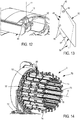
- FIGS. 14 to 17 and 19 and 20 show a portion of the device 2 forming an extractor 70.
- This extractor is slidably mounted with respect to the drum 2. It is also possible for this extractor to be common to several devices 2 and can be Associated at will with one or the other of the drums by moving it opposite these according to the needs. It will be assumed in the following that the horizontal main axis of the extractor coincides with the axis 6.
- the extractor comprises a frame 72 and a set of arms 74 all identical to each other and which are in this case 20 in number, this value not being limiting.
- the arms have an elongated horizontal rectilinear shape. They are regularly distributed around the axis 6 and extend opposite each other. The arms thus define between them an enclosure of generally cylindrical shape with a generally circular section in a plane perpendicular to the axis.
- the arms are borne cantilevered, all on the same side, by the frame 72 so that the arms are each movably mounted to slide on the frame in a direction radial to the axis 6. At any given moment , all the arms extend at the same radial distance from the axis.
- the extractor is arranged so that the arms can be moved simultaneously in the radial direction and in the same direction so as to approach all the axis or all away from it. At any moment of their movement, the arms are equidistant from the axis 6.
- Each arm has a concave inner face 76 of cylindrical shape to circular section in a plane perpendicular to the axis 6 and facing the latter. These faces are spaced from each other in circumferential direction to the axis.
- Each arm comprises rollers 78 rotatably mounted relative to a body of the arm about a common axis parallel to the axis 6.
- the face 76 has orifices through which the respective rollers can extend projecting from the face in the direction of the axis.
- the rollers of each arm are carried by a common member not shown and itself mounted movable relative to the body of the arm. This organ is able to make pebble take two different positions. In the first position, the rollers protrude from the face 76 in the direction of the axis 6. In the second, they do not extend projecting from this face and are housed integrally inside the arms .
- the extractor comprises centralized means for the control and the operation of the rollers allowing all of them to be placed simultaneously in the same position.
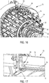
- the extractor is arranged to be able to receive between the arms the entire portion of the drum carrying the wall 10, as illustrated in FIG. figure 16 .
- the wall 10 possibly with the tread blank that it supports, extends facing the faces 76.
- one of the arms 74 is equipped with a retractable clamp 80 comprising two jaws 82, 84 movable relative to one another in radial direction and able to clamp together the free end of the wall 10 for the immobilize rigidly relative to the corresponding arm.
- the clamp 80 immobilizes rigidly relative to the corresponding arm the free end of the wall 10.
- the arms of the extractor are arranged so that the rollers 76 which are in the projecting position, extend in contact with the face 10 or almost in contact with it. The clamps are moved away from the wall 10.
- the drum is rotated relative to the extractor about the axis 6 in the direction corresponding to the increase in the diameter of the wall. This results in particular the rotation of the end of the wall 10 attached to the drum relative to its other end attached to the extractor. This also causes the increase in the diameter of the turns of the wall 10 which therefore bear against the rollers.
- the arms 74 are moved away so that the rollers accompany the movement of the turns. This positioning of the arms of the extractor allows to evenly distribute the deformation of the turns of the shell, otherwise there is a risk that only part of the turns deforms during movement.
- the distance between the spacers and the axis 6 is controlled. These operations are continued until the desired external diameter for the wall 10 is obtained.
- the free end of the wall is released by opening and withdrawing the clamp 80, then the flanges 54 are actuated so as to tighten the turns of the wall in the axial direction.
- the drum is then extracted from the extractor.
- the diameter of the wall 10 is adapted as explained above in order to obtain the desired diameter.
- one or more rubber elements are then wound on the wall 10 by rotating the drum about its axis so as to constitute the blank of the tread.
- the drum carrying the blank is introduced into the extractor, the rollers being in the retracted position and therefore not exceeding faces 76.
- the arms of the extractor are then brought closer to the axis in order to place their faces 76 in contact with the blank and to compress it radially. Once this contact is made, the diameter of the wall 10 is reduced as explained above.
- the latter is rotated in the direction in which the turns are tightened on the spacers.
- the blank remains in contact with the arms 74 against which it makes a uniform support and separates from the wall 10 whose diameter is reduced.
- the drum can then be extracted from the blank and the extractor. It is then sufficient to recover the blank always present in the extractor.
- this tread blank will be assembled with the other components of the tire to form a complete blank to be fired to, after vulcanization, form a tire casing.
- the device with vibrators 82 able, because of the vibrations they produce, to peel the wall 10 relative to the spacers 20 to facilitate their separation during changes in diameter.
- This variant can make it unnecessary to provide an extractor for changes in diameter.
- the vibrators can be placed under the spacers.
- the frame comprises two disks 90 of axis 6, rigidly fixed to the frame 72.
- the two disks are largely identical to one another. They have the same diameter and are separated by a space along the direction of the axis 6.
- the front disc has in its thickness identical through openings 92 forming rectilinear rectangular rails, the longitudinal direction of the rectangle extending in the radial direction.
- the number of slides is identical to that of the arms.
- Each arm has its rear end portion slidably mounted in the corresponding slide in the radial direction.
- the rear disc comprises radial rods 94 also associated with the arms bijectively, each rod being slidably mounted in the end portion of the corresponding arm.
- the rods are rigidly attached to the rear disc.
- the arms are carried by the two disks and mounted sliding radially on them.
- the extractor further comprises a cam 96 also having a form of axis disc 6.
- the cam is rotatably mounted about this axis relative to the frame 72 and relative to the discs 90.
- the cam has in its thickness identical through openings 98 forming rectilinear slides, the longitudinal direction of each slide being inclined relative to the radial direction.
- the slides 98 are the image of one another by a rotation of axis 6 and constant angle The number of slides is identical to that of the arms.
- Each arm at its rear end portion slidably mounted in the corresponding slide in the plane of the cam.
- the slide 98 of each arm being inclined relative to the slide 90 of the same arm, the rotation of the cam 96 relative to the discs 90 causes the sliding of the arms in the radial direction.
- the extractor comprises motorization means formed in this case by a jack 100 comprising a body 102 articulated to the frame 72 and a rod 104 hinged to the cam 96.
- the longitudinal direction of the jack is parallel to the general plane of the cam and perpendicular to the axis 6 without being secant with the latter.
- the sliding of the rod relative to the body thus causes the rotation of the cam and the radial sliding of the arms. This mechanism therefore allows the simultaneous movement of the arms, the arms remaining equidistant from the axis at each moment of their movement.
- rollers on the extractor it will be possible to dispense with providing rollers on the extractor. Indeed, it can be provided that the rolling of the rubber component or that of the turns when changing the diameter of the drum is done with a roller or roller device which is independent of the extractor.
- the extractor then performs only the following two functions: first, when increasing the diameter of the drum, maintaining its helical wall along its generator to ensure its uniform deployment so that all the turns have the same amplitude of movement, on the other hand, during the extraction of the rubber ring, maintaining the ring in tension so that it keeps its circular shape while reducing the diameter of the drum in order to prevent the ring from sticking to the spring, follow it and deform.
- roller or rollers could be mounted movable in the axial direction relative to the frame to perform the rolling of different sections of the component.
Landscapes
- Engineering & Computer Science (AREA)
- Mechanical Engineering (AREA)
- Tyre Moulding (AREA)
Claims (13)
- Anlage zur Herstellung einer Reifenkomponente aus Rohgummi, welche wenigstens eine Trommel (2) zur Fertigung der Komponente und eine Vorrichtung (70) zur Handhabung der Komponente umfasst,
wobei die Trommel eine schraubenlinienförmige Außenwand (10) und Mittel (20) zur Regelung eines Durchmessers der Wand umfasst,
wobei die Vorrichtung ein Gestell (72) und Arme (74) umfasst, die sich einander gegenüber parallel zu einer Hauptachse (6) der Vorrichtung erstrecken und in zur Achse radialer Richtung beweglich angebracht sind, derart, dass sie nur in Äquidistanz von der Achse beweglich sind. - Anlage nach dem vorhergehenden Anspruch, welche Führungsmittel (90) zur Führung einer radialen Bewegung der Arme umfasst, wobei die Führungsmittel zum Beispiel Gleitschienen (92) umfassen.
- Anlage nach dem vorhergehenden Anspruch, welche Mittel (96) zur Betätigung der Arme umfasst, die von den Führungsmitteln unabhängig sind.
- Anlage nach wenigstens einem der Ansprüche 2 bis 3, welche einen Nocken (96) umfasst, der in der Lage ist, die Arme zu betätigen, und beweglich bezüglich der Führungsmittel angebracht ist.
- Anlage nach dem vorhergehenden Anspruch, wobei der Nocken Gleitschienen (98) aufweist, die sich in einer zur Achse senkrechten Ebene erstrecken.
- Anlage nach wenigstens einem der vorhergehenden Ansprüche, wobei wenigstens einer der Arme wenigstens eine Rolle (78) aufweist, die in der Lage ist, sich aus dem Arm in Richtung der Achse vorstehend zu erstrecken.
- Anlage nach dem vorhergehenden Anspruch, wobei die Rolle (78) beweglich angebracht ist, derart, dass sie eine Position einnehmen kann, in der sie sich nicht aus dem Arm in Richtung der Achse vorstehend erstreckt.
- Anlage nach wenigstens einem der vorhergehenden Ansprüche, wobei jeder Arm (74) wenigstens eine Rolle aufweist.
- Anlage nach wenigstens einem der Ansprüche 6 bis 8, wobei die Anzahl der Rollen (78) für jeden Arm wenigstens zwei beträgt.
- Anlage nach wenigstens einem der vorhergehenden Ansprüche, welche wenigstens eine Zange (80) aufweist, die in der Lage ist, ein Element in der Zange zu halten, indem sie es starr an einem der Arme fixiert.
- Verfahren zur Herstellung einer Reifenkomponente aus Rohgummi, wobei mittels einer Anlage nach einem der Ansprüche 1 bis 10:- um die Trommel (2) herum, die eine Reifenkomponente aus Rohgummi trägt, die von dem Gestell getragenen Arme (74) angeordnet werden, und- die Arme in zur Achse radialer Richtung verlagert werden, derart, dass die Arme äquidistant von der Achse bleiben, und derart, dass die Arme in Kontakt mit der Komponente gebracht werden.
- Verfahren nach dem vorhergehenden Anspruch, wobei, wenn wenigstens einer der Arme wenigstens eine Rolle (78) aufweist, die oder jede Rolle auf der Komponente rollen gelassen wird bzw. werden.
- Verfahren nach wenigstens einem der Ansprüche 11 bis 12, wobei eine radiale Abmessung der Trommel (2) verringert wird, so dass bewirkt wird, dass die Komponente ausschließlich von den Armen getragen wird.
Applications Claiming Priority (2)
| Application Number | Priority Date | Filing Date | Title |
|---|---|---|---|
| FR1259464A FR2996493B1 (fr) | 2012-10-05 | 2012-10-05 | Dispositif de manutention d'un composant d'une enveloppe de pneumatique |
| PCT/FR2013/052378 WO2014057196A1 (fr) | 2012-10-05 | 2013-10-07 | Installation et procédé de realisation d'un composant de pneumatique en gomme crue |
Publications (2)
| Publication Number | Publication Date |
|---|---|
| EP2903810A1 EP2903810A1 (de) | 2015-08-12 |
| EP2903810B1 true EP2903810B1 (de) | 2018-09-05 |
Family
ID=47598879
Family Applications (1)
| Application Number | Title | Priority Date | Filing Date |
|---|---|---|---|
| EP13786684.4A Active EP2903810B1 (de) | 2012-10-05 | 2013-10-07 | Vorrichtung und verfahren zur herstellung einer reifenkomponente aus rohgummi |
Country Status (3)
| Country | Link |
|---|---|
| EP (1) | EP2903810B1 (de) |
| FR (1) | FR2996493B1 (de) |
| WO (1) | WO2014057196A1 (de) |
Families Citing this family (4)
| Publication number | Priority date | Publication date | Assignee | Title |
|---|---|---|---|---|
| FR3030350B1 (fr) * | 2014-12-19 | 2017-01-06 | Michelin & Cie | Procede et installation pour l’assemblage d’une ebauche de pneumatique |
| FR3031695B1 (fr) * | 2015-01-16 | 2017-02-24 | Michelin & Cie | Tambour de confection d'une ebauche de pneumatique |
| NL2029073B1 (en) * | 2021-08-27 | 2023-03-15 | Vmi Holland Bv | Gripper, gripper station and method for gripping an annular tire component |
| CN116653329A (zh) * | 2023-03-15 | 2023-08-29 | 桂林梵玛科机械有限公司 | 胎胚上趾口修复托举装置 |
Family Cites Families (5)
| Publication number | Priority date | Publication date | Assignee | Title |
|---|---|---|---|---|
| DE1181901B (de) * | 1961-07-08 | 1964-11-19 | Continental Gummi Werke Ag | Vorrichtung an einer Reifenaufbaumaschine zum Aufziehen ringfoermig geschlossener, elastischer Werkstoffbandagen auf die Reifenaufbautrommel |
| JPS5149283A (en) * | 1974-10-25 | 1976-04-28 | Bridgestone Tire Co Ltd | Namataiyaseikeihoho oyobi sonosochi |
| DE2609657A1 (de) * | 1976-03-09 | 1977-09-15 | Harry Ing Grad Rost | Verfahren und vorrichtung zum aufbringen von bandagen auf eine reifenbautrommel |
| US5441587A (en) * | 1994-08-12 | 1995-08-15 | Wyko, Inc. | Transfer ring having selective adjustability of shoe movement |
| JP4634465B2 (ja) * | 2006-01-12 | 2011-02-16 | 東洋ゴム工業株式会社 | カーカスバンドの成型方法及びステッチャー装置 |
-
2012
- 2012-10-05 FR FR1259464A patent/FR2996493B1/fr active Active
-
2013
- 2013-10-07 EP EP13786684.4A patent/EP2903810B1/de active Active
- 2013-10-07 WO PCT/FR2013/052378 patent/WO2014057196A1/fr not_active Ceased
Also Published As
| Publication number | Publication date |
|---|---|
| FR2996493A1 (fr) | 2014-04-11 |
| WO2014057196A1 (fr) | 2014-04-17 |
| FR2996493B1 (fr) | 2016-12-23 |
| EP2903810A1 (de) | 2015-08-12 |
Similar Documents
| Publication | Publication Date | Title |
|---|---|---|
| EP0906186B1 (de) | Aufbautrommel zur luftreifenherstellung | |
| EP3233457B1 (de) | Verfahren und ausrüstung zur montage eines reifenrohlings | |
| EP0875476B1 (de) | Wickler mit zwei Spindeln zum Aufwickeln einer Bahn | |
| EP2903810B1 (de) | Vorrichtung und verfahren zur herstellung einer reifenkomponente aus rohgummi | |
| FR2491823A1 (fr) | Procede et dispositif pour la fabrication de pneumatiques radiaux comprenant une carcasse, une structure annulaire de renforcement et une bande de roulement, la structure annulaire de renforcement et la bande de roulement etant fabriquees sur deux tambours differents | |
| EP3380312B1 (de) | Trommel und verfahren zur montage eines reifenadapters auf einer radfelge | |
| EP3245052B1 (de) | Trommel zum herstellen eines reifenrohlings | |
| CA2790180C (fr) | Procede d'exploitation d'une machine de tressage de fibres renforcantes | |
| EP2903808B1 (de) | Vorrichtung zur herstellung einer lauffläche eines reifenrohlings | |
| EP2903809B1 (de) | Verfahren zur herstellung einer wand einer vorrichtung zur herstellung eines profils eines reifengehäuses | |
| EP0953435B1 (de) | Verfahren zur Herstellung von Luftreifen und Reifenaufbautrommel zur Durchführung dieses Verfahrens | |
| EP2750869B1 (de) | Reifenaufbautrommel mit beweglichen sektoren | |
| FR3066430A1 (fr) | Tambour et procede d'assemblage d'un adaptateur de pneumatique sur une jante | |
| FR3030349A1 (fr) | Dispositif et procede pour la fabrication de pneumatiques | |
| EP3458253B1 (de) | Verfahren und vorrichtung zur umschlagung eines reifenrohlings | |
| EP3458256B1 (de) | Faltsystem zur herstellung von reifenrohlingen | |
| EP3458254B1 (de) | Aufklappsystem zur herstellung von reifenrohlingen. | |
| EP1793037B1 (de) | Presswalze mit flexiblem Mantel für eine Schuhpresse | |
| FR3108556A1 (fr) | Tambour de confection d’un adaptateur de pneumatique sur une jante | |
| FR2881976A1 (fr) | Machine et procede de marquage d'un objet | |
| FR3059593A1 (fr) | Tambour de fabrication d'ebauche ou de composant de pneumatique |
Legal Events
| Date | Code | Title | Description |
|---|---|---|---|
| PUAI | Public reference made under article 153(3) epc to a published international application that has entered the european phase |
Free format text: ORIGINAL CODE: 0009012 |
|
| 17P | Request for examination filed |
Effective date: 20150401 |
|
| AK | Designated contracting states |
Kind code of ref document: A1 Designated state(s): AL AT BE BG CH CY CZ DE DK EE ES FI FR GB GR HR HU IE IS IT LI LT LU LV MC MK MT NL NO PL PT RO RS SE SI SK SM TR |
|
| AX | Request for extension of the european patent |
Extension state: BA ME |
|
| DAX | Request for extension of the european patent (deleted) | ||
| RAP1 | Party data changed (applicant data changed or rights of an application transferred) |
Owner name: COMPAGNIE GENERALE DES ETABLISSEMENTS MICHELIN |
|
| RAP1 | Party data changed (applicant data changed or rights of an application transferred) |
Owner name: COMPAGNIE GENERALE DES ETABLISSEMENTS MICHELIN |
|
| GRAP | Despatch of communication of intention to grant a patent |
Free format text: ORIGINAL CODE: EPIDOSNIGR1 |
|
| STAA | Information on the status of an ep patent application or granted ep patent |
Free format text: STATUS: GRANT OF PATENT IS INTENDED |
|
| INTG | Intention to grant announced |
Effective date: 20180514 |
|
| GRAS | Grant fee paid |
Free format text: ORIGINAL CODE: EPIDOSNIGR3 |
|
| GRAA | (expected) grant |
Free format text: ORIGINAL CODE: 0009210 |
|
| STAA | Information on the status of an ep patent application or granted ep patent |
Free format text: STATUS: THE PATENT HAS BEEN GRANTED |
|
| AK | Designated contracting states |
Kind code of ref document: B1 Designated state(s): AL AT BE BG CH CY CZ DE DK EE ES FI FR GB GR HR HU IE IS IT LI LT LU LV MC MK MT NL NO PL PT RO RS SE SI SK SM TR |
|
| REG | Reference to a national code |
Ref country code: GB Ref legal event code: FG4D Free format text: NOT ENGLISH |
|
| REG | Reference to a national code |
Ref country code: CH Ref legal event code: EP |
|
| REG | Reference to a national code |
Ref country code: AT Ref legal event code: REF Ref document number: 1037302 Country of ref document: AT Kind code of ref document: T Effective date: 20180915 |
|
| REG | Reference to a national code |
Ref country code: IE Ref legal event code: FG4D Free format text: LANGUAGE OF EP DOCUMENT: FRENCH |
|
| REG | Reference to a national code |
Ref country code: DE Ref legal event code: R096 Ref document number: 602013043225 Country of ref document: DE |
|
| REG | Reference to a national code |
Ref country code: FR Ref legal event code: PLFP Year of fee payment: 6 |
|
| RAP2 | Party data changed (patent owner data changed or rights of a patent transferred) |
Owner name: COMPAGNIE GENERALE DES ETABLISSEMENTS MICHELIN |
|
| REG | Reference to a national code |
Ref country code: NL Ref legal event code: FP |
|
| REG | Reference to a national code |
Ref country code: LT Ref legal event code: MG4D |
|
| PG25 | Lapsed in a contracting state [announced via postgrant information from national office to epo] |
Ref country code: RS Free format text: LAPSE BECAUSE OF FAILURE TO SUBMIT A TRANSLATION OF THE DESCRIPTION OR TO PAY THE FEE WITHIN THE PRESCRIBED TIME-LIMIT Effective date: 20180905 Ref country code: LT Free format text: LAPSE BECAUSE OF FAILURE TO SUBMIT A TRANSLATION OF THE DESCRIPTION OR TO PAY THE FEE WITHIN THE PRESCRIBED TIME-LIMIT Effective date: 20180905 Ref country code: GR Free format text: LAPSE BECAUSE OF FAILURE TO SUBMIT A TRANSLATION OF THE DESCRIPTION OR TO PAY THE FEE WITHIN THE PRESCRIBED TIME-LIMIT Effective date: 20181206 Ref country code: BG Free format text: LAPSE BECAUSE OF FAILURE TO SUBMIT A TRANSLATION OF THE DESCRIPTION OR TO PAY THE FEE WITHIN THE PRESCRIBED TIME-LIMIT Effective date: 20181205 Ref country code: NO Free format text: LAPSE BECAUSE OF FAILURE TO SUBMIT A TRANSLATION OF THE DESCRIPTION OR TO PAY THE FEE WITHIN THE PRESCRIBED TIME-LIMIT Effective date: 20181205 Ref country code: FI Free format text: LAPSE BECAUSE OF FAILURE TO SUBMIT A TRANSLATION OF THE DESCRIPTION OR TO PAY THE FEE WITHIN THE PRESCRIBED TIME-LIMIT Effective date: 20180905 Ref country code: SE Free format text: LAPSE BECAUSE OF FAILURE TO SUBMIT A TRANSLATION OF THE DESCRIPTION OR TO PAY THE FEE WITHIN THE PRESCRIBED TIME-LIMIT Effective date: 20180905 |
|
| REG | Reference to a national code |
Ref country code: AT Ref legal event code: MK05 Ref document number: 1037302 Country of ref document: AT Kind code of ref document: T Effective date: 20180905 |
|
| PG25 | Lapsed in a contracting state [announced via postgrant information from national office to epo] |
Ref country code: HR Free format text: LAPSE BECAUSE OF FAILURE TO SUBMIT A TRANSLATION OF THE DESCRIPTION OR TO PAY THE FEE WITHIN THE PRESCRIBED TIME-LIMIT Effective date: 20180905 Ref country code: LV Free format text: LAPSE BECAUSE OF FAILURE TO SUBMIT A TRANSLATION OF THE DESCRIPTION OR TO PAY THE FEE WITHIN THE PRESCRIBED TIME-LIMIT Effective date: 20180905 Ref country code: AL Free format text: LAPSE BECAUSE OF FAILURE TO SUBMIT A TRANSLATION OF THE DESCRIPTION OR TO PAY THE FEE WITHIN THE PRESCRIBED TIME-LIMIT Effective date: 20180905 |
|
| PG25 | Lapsed in a contracting state [announced via postgrant information from national office to epo] |
Ref country code: RO Free format text: LAPSE BECAUSE OF FAILURE TO SUBMIT A TRANSLATION OF THE DESCRIPTION OR TO PAY THE FEE WITHIN THE PRESCRIBED TIME-LIMIT Effective date: 20180905 Ref country code: IT Free format text: LAPSE BECAUSE OF FAILURE TO SUBMIT A TRANSLATION OF THE DESCRIPTION OR TO PAY THE FEE WITHIN THE PRESCRIBED TIME-LIMIT Effective date: 20180905 Ref country code: CZ Free format text: LAPSE BECAUSE OF FAILURE TO SUBMIT A TRANSLATION OF THE DESCRIPTION OR TO PAY THE FEE WITHIN THE PRESCRIBED TIME-LIMIT Effective date: 20180905 Ref country code: IS Free format text: LAPSE BECAUSE OF FAILURE TO SUBMIT A TRANSLATION OF THE DESCRIPTION OR TO PAY THE FEE WITHIN THE PRESCRIBED TIME-LIMIT Effective date: 20190105 Ref country code: AT Free format text: LAPSE BECAUSE OF FAILURE TO SUBMIT A TRANSLATION OF THE DESCRIPTION OR TO PAY THE FEE WITHIN THE PRESCRIBED TIME-LIMIT Effective date: 20180905 Ref country code: ES Free format text: LAPSE BECAUSE OF FAILURE TO SUBMIT A TRANSLATION OF THE DESCRIPTION OR TO PAY THE FEE WITHIN THE PRESCRIBED TIME-LIMIT Effective date: 20180905 Ref country code: PL Free format text: LAPSE BECAUSE OF FAILURE TO SUBMIT A TRANSLATION OF THE DESCRIPTION OR TO PAY THE FEE WITHIN THE PRESCRIBED TIME-LIMIT Effective date: 20180905 Ref country code: EE Free format text: LAPSE BECAUSE OF FAILURE TO SUBMIT A TRANSLATION OF THE DESCRIPTION OR TO PAY THE FEE WITHIN THE PRESCRIBED TIME-LIMIT Effective date: 20180905 |
|
| PG25 | Lapsed in a contracting state [announced via postgrant information from national office to epo] |
Ref country code: SM Free format text: LAPSE BECAUSE OF FAILURE TO SUBMIT A TRANSLATION OF THE DESCRIPTION OR TO PAY THE FEE WITHIN THE PRESCRIBED TIME-LIMIT Effective date: 20180905 Ref country code: PT Free format text: LAPSE BECAUSE OF FAILURE TO SUBMIT A TRANSLATION OF THE DESCRIPTION OR TO PAY THE FEE WITHIN THE PRESCRIBED TIME-LIMIT Effective date: 20190105 Ref country code: SK Free format text: LAPSE BECAUSE OF FAILURE TO SUBMIT A TRANSLATION OF THE DESCRIPTION OR TO PAY THE FEE WITHIN THE PRESCRIBED TIME-LIMIT Effective date: 20180905 |
|
| REG | Reference to a national code |
Ref country code: CH Ref legal event code: PL |
|
| REG | Reference to a national code |
Ref country code: DE Ref legal event code: R097 Ref document number: 602013043225 Country of ref document: DE |
|
| REG | Reference to a national code |
Ref country code: BE Ref legal event code: MM Effective date: 20181031 |
|
| PG25 | Lapsed in a contracting state [announced via postgrant information from national office to epo] |
Ref country code: LU Free format text: LAPSE BECAUSE OF NON-PAYMENT OF DUE FEES Effective date: 20181007 |
|
| PLBE | No opposition filed within time limit |
Free format text: ORIGINAL CODE: 0009261 |
|
| STAA | Information on the status of an ep patent application or granted ep patent |
Free format text: STATUS: NO OPPOSITION FILED WITHIN TIME LIMIT |
|
| REG | Reference to a national code |
Ref country code: IE Ref legal event code: MM4A |
|
| PG25 | Lapsed in a contracting state [announced via postgrant information from national office to epo] |
Ref country code: DK Free format text: LAPSE BECAUSE OF FAILURE TO SUBMIT A TRANSLATION OF THE DESCRIPTION OR TO PAY THE FEE WITHIN THE PRESCRIBED TIME-LIMIT Effective date: 20180905 Ref country code: MC Free format text: LAPSE BECAUSE OF FAILURE TO SUBMIT A TRANSLATION OF THE DESCRIPTION OR TO PAY THE FEE WITHIN THE PRESCRIBED TIME-LIMIT Effective date: 20180905 |
|
| 26N | No opposition filed |
Effective date: 20190606 |
|
| GBPC | Gb: european patent ceased through non-payment of renewal fee |
Effective date: 20181205 |
|
| PG25 | Lapsed in a contracting state [announced via postgrant information from national office to epo] |
Ref country code: LI Free format text: LAPSE BECAUSE OF NON-PAYMENT OF DUE FEES Effective date: 20181031 Ref country code: CH Free format text: LAPSE BECAUSE OF NON-PAYMENT OF DUE FEES Effective date: 20181031 Ref country code: BE Free format text: LAPSE BECAUSE OF NON-PAYMENT OF DUE FEES Effective date: 20181031 Ref country code: SI Free format text: LAPSE BECAUSE OF FAILURE TO SUBMIT A TRANSLATION OF THE DESCRIPTION OR TO PAY THE FEE WITHIN THE PRESCRIBED TIME-LIMIT Effective date: 20180905 |
|
| PG25 | Lapsed in a contracting state [announced via postgrant information from national office to epo] |
Ref country code: IE Free format text: LAPSE BECAUSE OF NON-PAYMENT OF DUE FEES Effective date: 20181007 |
|
| PG25 | Lapsed in a contracting state [announced via postgrant information from national office to epo] |
Ref country code: GB Free format text: LAPSE BECAUSE OF NON-PAYMENT OF DUE FEES Effective date: 20181205 |
|
| PG25 | Lapsed in a contracting state [announced via postgrant information from national office to epo] |
Ref country code: MT Free format text: LAPSE BECAUSE OF FAILURE TO SUBMIT A TRANSLATION OF THE DESCRIPTION OR TO PAY THE FEE WITHIN THE PRESCRIBED TIME-LIMIT Effective date: 20180905 |
|
| PG25 | Lapsed in a contracting state [announced via postgrant information from national office to epo] |
Ref country code: TR Free format text: LAPSE BECAUSE OF FAILURE TO SUBMIT A TRANSLATION OF THE DESCRIPTION OR TO PAY THE FEE WITHIN THE PRESCRIBED TIME-LIMIT Effective date: 20180905 |
|
| PG25 | Lapsed in a contracting state [announced via postgrant information from national office to epo] |
Ref country code: CY Free format text: LAPSE BECAUSE OF FAILURE TO SUBMIT A TRANSLATION OF THE DESCRIPTION OR TO PAY THE FEE WITHIN THE PRESCRIBED TIME-LIMIT Effective date: 20180905 Ref country code: MK Free format text: LAPSE BECAUSE OF NON-PAYMENT OF DUE FEES Effective date: 20180905 Ref country code: HU Free format text: LAPSE BECAUSE OF FAILURE TO SUBMIT A TRANSLATION OF THE DESCRIPTION OR TO PAY THE FEE WITHIN THE PRESCRIBED TIME-LIMIT; INVALID AB INITIO Effective date: 20131007 |
|
| PGFP | Annual fee paid to national office [announced via postgrant information from national office to epo] |
Ref country code: NL Payment date: 20251021 Year of fee payment: 13 |
|
| PGFP | Annual fee paid to national office [announced via postgrant information from national office to epo] |
Ref country code: DE Payment date: 20251021 Year of fee payment: 13 |
|
| PGFP | Annual fee paid to national office [announced via postgrant information from national office to epo] |
Ref country code: FR Payment date: 20251030 Year of fee payment: 13 |